US3338460A - Containers - Google Patents
Containers Download PDFInfo
- Publication number
- US3338460A US3338460A US473623A US47362365A US3338460A US 3338460 A US3338460 A US 3338460A US 473623 A US473623 A US 473623A US 47362365 A US47362365 A US 47362365A US 3338460 A US3338460 A US 3338460A
- Authority
- US
- United States
- Prior art keywords
- wall
- line
- slider
- runway
- lid
- Prior art date
- Legal status (The legal status is an assumption and is not a legal conclusion. Google has not performed a legal analysis and makes no representation as to the accuracy of the status listed.)
- Expired - Lifetime
Links
- 239000000463 material Substances 0.000 claims description 73
- 238000004519 manufacturing process Methods 0.000 description 11
- 239000005028 tinplate Substances 0.000 description 9
- 238000005304 joining Methods 0.000 description 7
- 238000000034 method Methods 0.000 description 7
- XAGFODPZIPBFFR-UHFFFAOYSA-N aluminium Chemical compound [Al] XAGFODPZIPBFFR-UHFFFAOYSA-N 0.000 description 5
- 229910052782 aluminium Inorganic materials 0.000 description 5
- 238000005452 bending Methods 0.000 description 5
- 239000004411 aluminium Substances 0.000 description 3
- 239000011324 bead Substances 0.000 description 2
- 239000004033 plastic Substances 0.000 description 2
- 229920003023 plastic Polymers 0.000 description 2
- 238000000926 separation method Methods 0.000 description 2
- 239000007787 solid Substances 0.000 description 2
- 238000005728 strengthening Methods 0.000 description 2
- 238000013459 approach Methods 0.000 description 1
- 238000010276 construction Methods 0.000 description 1
- 238000005336 cracking Methods 0.000 description 1
- 238000005520 cutting process Methods 0.000 description 1
- 229910052571 earthenware Inorganic materials 0.000 description 1
- 239000011521 glass Substances 0.000 description 1
- 230000003993 interaction Effects 0.000 description 1
- 239000007788 liquid Substances 0.000 description 1
- 238000012856 packing Methods 0.000 description 1
- 230000002093 peripheral effect Effects 0.000 description 1
- 238000003825 pressing Methods 0.000 description 1
- 230000003014 reinforcing effect Effects 0.000 description 1
- 238000004826 seaming Methods 0.000 description 1
- 230000003313 weakening effect Effects 0.000 description 1
Images
Classifications
-
- B—PERFORMING OPERATIONS; TRANSPORTING
- B65—CONVEYING; PACKING; STORING; HANDLING THIN OR FILAMENTARY MATERIAL
- B65D—CONTAINERS FOR STORAGE OR TRANSPORT OF ARTICLES OR MATERIALS, e.g. BAGS, BARRELS, BOTTLES, BOXES, CANS, CARTONS, CRATES, DRUMS, JARS, TANKS, HOPPERS, FORWARDING CONTAINERS; ACCESSORIES, CLOSURES, OR FITTINGS THEREFOR; PACKAGING ELEMENTS; PACKAGES
- B65D17/00—Rigid or semi-rigid containers specially constructed to be opened by cutting or piercing, or by tearing of frangible members or portions
- B65D17/28—Rigid or semi-rigid containers specially constructed to be opened by cutting or piercing, or by tearing of frangible members or portions at lines or points of weakness
-
- B—PERFORMING OPERATIONS; TRANSPORTING
- B65—CONVEYING; PACKING; STORING; HANDLING THIN OR FILAMENTARY MATERIAL
- B65D—CONTAINERS FOR STORAGE OR TRANSPORT OF ARTICLES OR MATERIALS, e.g. BAGS, BARRELS, BOTTLES, BOXES, CANS, CARTONS, CRATES, DRUMS, JARS, TANKS, HOPPERS, FORWARDING CONTAINERS; ACCESSORIES, CLOSURES, OR FITTINGS THEREFOR; PACKAGING ELEMENTS; PACKAGES
- B65D17/00—Rigid or semi-rigid containers specially constructed to be opened by cutting or piercing, or by tearing of frangible members or portions
- B65D17/28—Rigid or semi-rigid containers specially constructed to be opened by cutting or piercing, or by tearing of frangible members or portions at lines or points of weakness
- B65D17/34—Arrangement or construction of pull or lift tabs
- B65D17/347—Arrangement or construction of pull or lift tabs characterised by the connection between the tab and a detachable member or portion of the container
- B65D17/353—Arrangement or construction of pull or lift tabs characterised by the connection between the tab and a detachable member or portion of the container the connecting means being integral with the tab or with the detachable member or portion
Definitions
- CONTAINERS Filed July 21, 1965 4 Sheets-Sheet 2 W. COOKSON Aug. 29, 1967 CONTAINERS 4 Sheets-Sheet 3 Filed July 21, 1965 W. COO'KSON Aug. 29, 1967 CONTAINERS 4 Sheets-Sheet 4 Filed July 21, 1965 jay];
- This invention relates to containers and container walls having means provided for their easy opening. It is more particularly, though not exclusively, concerned with container lids formed of relatively stiff thin sheet material provi-ded with easily operated opening means.
- the invention relates to a container having a lid formed of tin plate having hand operable opening means.
- this invention provides in a container wall formed of relatively thin sheet material
- opening means comprising:
- camming means provided on the slider opening device engageable with the material of the wall in the neighbourhood of the weakened portion to exert pressure thereon to part the material along the said line when the slider opening device is slid along the runway.
- a weakened portion may be provided at the base of the raised portion which is parted by the pressure of the camming means allowing the latter to burst through the wall and engage thereunder.
- the weakened portion leads into a weakened portion adjacent the runway along which the material will be parted as the slider device is moved further along the runway.
- camming means which exert pressure on a portion of a container wall as the one part is hinged about the other by lifting.
- an openable portion can be separated from the remainder of the wall along a pre-formed line by lifting one part of the opening device and can then be further separated along the pre-formed line by moving the slider opening device along the runway.
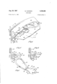
- FIG. 1 is a part-perspective view of a container having a lid provided with opening means with the slider opening device in the non-operative position;
- FIG. 2 is a part cross-sectional view of the lid with its slider device shown in FIG. 1 taken on the line H-II;
- FIG. 3 is a similar view to FIG. 2 taken on the line IIIIII in FIG. 1 with the slider device omitted;
- FIG. 4 is a perspective view of the slider opening device shown in FIGS. 1 and 2;
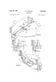
- FIG. 5 is a part-perspective view of the container shownin FIG. 1 with the slider device in its operative position;
- FIG. 6 is a cross-sectional view of the container shown in FIG. 5 taken on the line VI-VI;
- FIG. 7 is a part cross-s-ectional view of the container shown in FIG. 5 during the movement of the slider de-- vice round the runway, and
- FIG. 8 is a part-perspective view of the container shown in FIG. 5 during the movement round the runway of the slider device, parts being broken away for clarity.
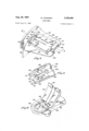
- FIG. 9 is a part-perspective view of another form of opening means for the lid of a container with its slider opening device in the non-operative position;
- FIG. '10 is a part cross-section view of the opening means shown in FIG. 9, taken on the line'XX;
- FIG. 11 is a perspective view from below of the slider device shown in FIGS. 9 and 10;
- FIG. 12 is a view of the container with the opening means in the lid the slider device being omitted;
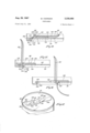
- FIG. 13 is a part cross-section view of the opening means taken on the line XX in FIG. 9, but With the slider device in its first operative position;
- FIG. 14 is a part cross-section view of the opening means similar to FIG. 13 but with the slider device in its second operative position.
- FIG. 15 is a perspective View of the opening means during the process of opening the container.
- FIGS. 1, 2 and 3 there is shown a container having a body 10 and a lid 12 made of tin-plate, aluminum orother suitable relatively stiff thin sheet material, joined ay a conventional seam joint 14.
- Opening means for the id 12, generally indicated at 16 in FIG. 1 comprise a runvay element 18 and a slider opening device 20.
- the runvay 18 is formed round the periphery of the lid 12 below he top of its inner rim 22 and forms a runway or guide For the slider device 20.
- the runway 18 is provided with r shoulder 24 shown in section in FIGS. 2 and 3.
- the runway 18 has a base wall 26 and an inner wall 28 facing a bottom portion 30 of the rim 22 to provide 1 channel 32.
- a top portion of the inner wall 28 is inwardly bent at 34 and reversibly bent at 36 to provide engagement means 40 including a ledge 38 for engagement by'the slider device 20 (see FIGS. 2 and 3).
- the shoulder 24 is formed by an outward bend 42 and a reverse bend 44 (FIG. 3).
- the engagement means 40 are separated from the rim 22 by an opening 46.
- a scored, that is partly cut, line 56 is provided in the surface of the lid 12 round the base of the shoulder 24.
- a raised portion 50 Adjacent to a portion of the runway 18 and of the scored line 56 is a raised portion 50 constituting a guide element having a front wall 52 which lies at a slight angle to the runway 18 (see FIGS. 1 and 3).
- the purpose of the scored lines (56 and 58) is to form a weakened portion in the material of the lid 12 so that it is in the first place easily rupturable by camming means (hereinafter described) of the slider device 20 and so that secondly the said camming means may cause the material to part along the scored line as the slider device 20 is slid along the runway element 18.
- the raised portion 50 and the scored lines 56 and 58 may be considered as a part of the opening means 16.
- the lines 56 and 58 may be otherwise weakened, for example by coining that is thinning the material instead of cutting it. Coining is applicable when the material is easily rupturable.
- the scored or coined lines may be made in the underneath surface of the lid 12, or in both the top and underneath surfaces.
- the wall 28 and the shoulder 24 provide support for the material of the lid 12 in the region of the scored lines 56 and'58 so that this weakened portion of the lid is protected from damage.
- the runway 18 (and to a smaller extent the raised portion 50) provide a rigid structure for the lid and so compensate for weakening of the lid by the scored lines 56 and 58.
- the weakened portion of the lid is also protected from damage by being below the top of the inner rim 22 of the lid, and this feature also protects the runway 18 and slider device 20.
- the slider device 20 made from tin-plate, aluminum or other suitable material, comprises a top-wall 60, a side wall 62 and inwardly bent engagement means 64 and 66 one on each side of the side wall 62.
- the top wall 60 is extended to form camming means 70.
- the slider device 20 is of such dimensions that it is an easy sliding fit on runway 18 when the engagement means 64 and 66 are in contact with the engagement means 40 including the ledge 38 of the lid 12. When assembled in this position the side wall 62 is located in the gap 46 (FIGS.
- a handle 72 suitable for hand operation is provided at one end of the slider 20 and is preferably provided with hemmed edges 74 as shown in FIG. 4 for strengthening and ease, comfort and safety in manipulation.
- the handle 72 may be upwardly bent, a portion of the slider device 20 at the ends 76 of the hemmed edges 74 of the handle bending to form a hinge 80.
- the slider opening device 20 is shown in its non-operative position. It is assembled on runway 18 in the course of manufacture of the lid while this is being formed in suitable press tools. After manufacture, the lid 12 with its assembled slider device 20, is secured to the container body 10 in conventional seaming machines by means of the lock-seam joint 14. A first step in the process of opening the container is shown in FIG. 5.
- the handle 72 of the slider opening device 20 is lifted by hand, the material of the device 20 bending about its hinge 80, until the handle 72 is in an upright position as illustrated in FIG. 5.
- the slider opening device 20 is then slid by hand along the runway 18 until the camming means 70 engages the front wall 52 of the raised portion 50 and the material of the lid 12 at or near the partial cut 58.
- the camming means 70 exerts pressure on the front wall 52 of the raised portion 50 because the wall 52 lies at a slight angle to the runway 18 as previously explained. This causes separation of the material of the lid along the line 58 and consequently the camming means 70 bursts through the material of the lid becoming located under the wall 52 which is inwardly bent as shown in FIG. 6.
- the camming means 70 parts the material of the lid on each side of the scored line 58 and then the material on each side of the scored line 56 at the base of the shoulder 24, line 58 leading in to line 56. Because the camming means 70 has become located underneath the inwardly bent wall 52 on rupturing the lid (as shown in FIG. 6) it remains located under peripheral edge 84 of a central removable portion 82 of the lid (see FIG. 7). This portion 82 is defined by the scored line 56. The camming means exerts pressure against the portion of the lid 12 weakened by the scored line 56 and so progressively parts the material on each side of the scored line. This is illustrated in FIGS.
- the camming means 70 lifts the edge 84 so parting the material along the scored line 56 a short distance in front of the camming means.
- the edge 84 is forced upwardly against the shoulder 24 the rigidity of which facilitates the parting action of the camming means.
- the removable portion 82 may be completely removed from the container. This will leave an opening equal in size to the internal cross-section of the container thus making simple, the removal of any form of contents from the container including e.g. solid contents closely packing the container and forming a single mass.
- the container wall 10 may occupy the position marked by broken lines in FIGS. 1 to 3 and 5 to 8 and although this leaves a small ledge at the mouth of the container when opened such a container is suitable for many types of goods.
- FIGS. 9 and 10 there is shown a container having a body 86 and a lid 88 made of tin-plate, aluminium, or other suitable relatively stiff thin sheet material, joined by a conventional seam joint 90.
- Opening means for the lid 88 generally indicated at 92 in FIG. 9 comprise an openable portion 94, a runway element 96, and a slider opening device 98.
- the openable portion 94 which is formed integrally in the lid 88, comprises part of a panel press formed in the lid having inwardly bent edges 102 to provide a runway element 104.
- the material is reversibly bent at 106 forming shoulders 108 and joining the material of the remainder of the lid 88.
- a scored or coined line 110 having a central curved portion joining two straight portions is made in the panel 100 above the edges of the shoulders 108.
- the line 110 defines an edge of the openable portion 94 and forms a weakened portion of the material of the lid on the runway element. In tin-plate, scoring will preferably be used for the line 110; in aluminium, coining may be used.
- the dotted line 112 in FIGS. 10 and 12 represents a line at which the openable portion 94 will bend or hinge as hereinafter described.
- the line 112 comes at a point on panel 100 covered by the slider opening device 98.
- the line may alternatively be made above the edges of the shoulders 108 but on the underneath surface of the panel 100 or a line may be made on both sides of the material.
- the slider opening device 98 is made from a single blank of tin-plate, aluminium, or other suitable material. It comprises an inner wall 114 having inwardly turned sides 117 and 118 providing respectively engagement means 120 and 122 in the form of opposed channel elements. The forward ends of sides 117 and 118 touch the rim of the container in the position shown in FIG. 9.
- the wall 114 is cut away at sides 124 and 125 to provide an opening 126 which extends as shown in FIG. 11 to a line 127 referred to as bend line 127.
- bend line 127 a central part of wall 114 is forwardly and slightly downwardly bent and then reversibly bent at an edge 130 to provide firstly a double hemmed portion 134 (FIGS.
- walls 114 and 132 with the necessary extensions to form the camming means may be made separately and spotwelded or otherwise secured together at the position of edge 130.
- the outer wall 132 has sides provided with downturned edges 140 lying close to the surface of the lid 88 when the slider opening device is in the non-operative position and an upturned end 141 capable of passing over the runway element 104 and allowing the user to slide his fingers underneath to raise the wall 132.
- the end 141 may have a hemmed edge (not shown) to prevent damage to the users fingers.
- the wall 132 thus provides a handle 142 for the slider opening device.
- the Wa-ll 132 has a central longitudinal bead 143 extending to the edge 130 of the portion 134 and the inner wall a corresponding central longitudinal bead 144. As the handle 142 is raised by the user, the wall 132 remains rigid with camming means 136, which together bend with respect to the inner wall 114 about the bend line 127.
- the slider device 98 is preferably fitted to the lid in the course of manufacture of the lid by press-forming in suitable tools.
- the engagement means 120 and 122 of the slider 98 are so dimensioned as to make a reasonably easy sliding fit on a left-hand portion 147 of the runway element 104.
- a right-hand portion 149 of the runway element 146 extends the runway substantially across the lid of the container as shown in FIG. 12.
- a runway element extending substantially across the lid or other wall makes it easier to avoid wrinkling of the surface of the sheet material during manufacture although a shorter runway element, e.g. a runway corresponding in length to he portion 147, could less preferably be used.
- the portion 149 is of narrower width than the portion 147 and while the engagement means 120, 122 engage the portion 147 (with a reasonably easy sliding fit) they are spaced sufficiently in relation to the width of the portion 149 to be capable of being loosely clipped on to the portion 149 during manufacture of the lid.
- the slider device 98 is then slid to the left (as would be seen in FIG. 12) to the position shown in FIG. 9 so that the engagement means slide over the portion 147, being guided, if necessary, by curves 151 joining the portions 147 and 149.
- the rim of the container forms a stop. When overlying the portion 147, the slider device 98 protects from damage the weakened portion of the panel 1.
- the camming means 136 is so proportioned in relation to the curved end of the scored or coined line 110 in panel 100 that by pivoting the handle 142 and camming means 136 round the bend line 127 with respect to the inner wall 114, when the slider opening device is in the position shown in FIG. 9, the edge 130 of the camming means 136 can be brought into contact with the panel 100 around the inside of the curved portion of the line 110.
- the point of contact is on an unsupported side of the scored or coined line, the panel 100 on the other side of the scored line being supported from underneath by the shoulder 108. Shoulder 108 also assists in reinforcing the construction of the opening device.
- FIG 13 A first step in the process of opening the container is shown in FIG 13.
- the handle 142 of the slider opening device 98 is lifted by hand so that together with the camming means 136 it hinges with respect to the inner portion 114.
- the material of the device bends about the bend line 127 in the inner wall 114 as shown in FIG. 13.
- the camming means 136 is thus brought into contact with the panel 100 as the handle 142 is raised.
- the edge 130 of the camming means 136 exerts pressure on the curved end of the openable portion 94 near the portion of the panel weakened by the line 110 causing the material of the panel to part along the curved portion of the line 110.
- the shoulders 108 provide the panel 100 outside the line with means of resistance against bending and thus facilitate the rupture of the material along the line.
- the engagement means and 122 slide freely on the portion 147 of the runway element 104.
- the camming means 136 progressively forces downwardly the openable. portion 94 aaginst the shoulders 108 and causes the mate-' rial of the panel 100 to part progressively along the opposite branches of the scored or coined line 110.
- the openable portion 94 bends downwardly below the lid 88 and when the material has parted along the full length of the line 110, it remains bent downwardly approximately from the line 112.
- the slider device 98 is prevented from further sliding movement by the camming means 136 jamming against the downbent portion v94.
- a part or the whole of the contents of the container may then be emptied through the opening left in the panel 100 by the openable portion 94.
- the slider opening device may be used to close the opening thus enabling the container to be used after being opened.
- the handle 142 is preferably returned to the non-operative position by bending it downwardly so that the downturned edges (FIG. 9) again lie close to the surface of the lid 88 and the camming means reverts to the non-operative position.
- the slider opening device is then slid back along the runway element 104 until the forward ends of sides 117 and 118 of the wall 114 touch the rim of the can as shown in FIG. 9.
- the slider opening device will in this position cover the opening that has been made because the line 112 marking the end of the opening comes beneath the slider opening device.
- the present embodiments of the invention provide opening means for a container. which s safe and easy to operate by the user with no loose parts cause damage.
- the invention also provides a method for the easy opening of a container without the necessity for providing separate tools. It can be applied to the lids or other walls of circular, oval and similarly shaped containers, whether the container bodies are formed of sheet material or glass, plastics, earthenware or other materials.
- plastics materials may also be used for the manufacture of the lids or other walls of containers having opening means as herein described and for the manufacture of the slider opening device.
- opening means comprising a runway element
- camming means provided on the slider opening device engageable with the material of the wall in the neighborhood of the weakened portion to exert pressure thereon to part the material along the said line when the slider opening device is slid along the runway.
- opening means comprising a runway element formed in the sheet material
- a slider opening device engageable with the runway element to be slid therealong; a portion of the material of the wall adjacent the runway element weakened along a line;
- camming means provided on the slider opening device engageable with the weakened portion of the material to exert pressure thereon to part progressively the said line as the slider opening device is slid along the runway.
- a container wall according to claim 4 having a removable portion completely surrounded by the runway and adjacent weakened portion so that the removable portion can be completely separated from the remainder of the wall by use of the slider opening device.
- a container according to claim 4 having a shoulder formed on one side of the weakened portion of the material to make said side more rigid and to assist in the parting action of the camming means along the said line.
- a container according to claim 5 having a shoulder formed on one side of the weakened portion of the material to make said side more rigid and to assist in the parting action of the camming means along the said line.
- a container wall according to claim 7 having a raised portion provided on the removable portion of the wall engageable by the camming means to break through the lid at the commencement of the opening operation.
- opening means comprising a runway element formed in the sheet material
- a slider opening device mountable on the runway element to slide therealong; a part of the runway element partially bounded by a weakened line formed in the material;
- camming means provided on the slider opening device engageable with the said part of the runway element adjacent the weakened line to exert pressure thereon and part progressively the weakened line as the slider opening device is slid along the runway element.
- a container wall according to claim 9 provided with a shoulder adjacent at least a part of the weakened line of material so that the camming means can exert pressure on the part of the runway element against the shoulder to assist in parting the weakened line.
- a wall formed of relatively stiff thin sheet material
- a continuous runway element formed in the wall an inwardly directed shoulder formed on the runway element above the wall; a weakened portion of the material of the Wall formed along a line adjacent the shoulder; a removable portion of the wall bounded by said line; a slider opening device mounted on the runway element; a handle on the slider opening device; engagement means on the slider opening device engaging the runway element; camming means formed on the slider opening device above the weakened portion of the wall and engageable therewith whereby on movement of the slider opening device along the runway element by hand pressure on the handle the camming means breaks through the material of the wall and lifts the removable portion of the wall against the shoulder so parting the material progressively along the said line and allowing the portion to be removed from the container.
- a container according to claim 11 having a raised portion formed in the removable portion of the wall engageable by the camming means as the slider opening device is slid along the runway element, whereby as the slider opening device is slid along the runway element the camming means engages the raised portion and breaks through the wall adjacent the raised portion prior to lifting the removable portion of the wall against the shoulder.
- a container according to claim 12 having a weakened portion formed in the material of the lid at the base of the raised portion joining the weakened portion adjacent the shoulder, the camming means breaking through the lid along the said first weakened portion as it engages the raised portion.
- a container according to claim 11 having a channel formed in the wall adjacent the runway element outwardly thereof, the slider opening device having a portion engageable with walls of the channel to maintainthe slider opening device in correct engagement with the runway element.
- a wall formed of relatively stiff thin sheet material
- an inner wall of the slider opening device being formed with opposed channel elements to engage the runway element to slide therealong;
- an outer wall of the slider opening device forming a handle hingeably connected to the inner wall
- camming means formed on the outer wall engageable with the openable portion of the panel when the handle is lifted about its connection with the inner wall, to break through the weakened line by pressing the panel against the shoulder, whereby, to open the container, the handle is lifted by hand pressure to break through the weakened line as aforesaid and then the slider opening device is urged along the runway element by hand pressure on the handle to part the material of the panel along the remainder of the weakened line so as to bend downwardly the openable portion of the panel.
- a container according to claim 15 having an extended portion formed continuously with the runway element of narrower width than the runway element over which the channel elements of the inner wall of the slider opening device can be loosely clipped during manufacture of the lid and then slid along to engage the runway element.
- a lid formed of tin plate
- a continuous runway element formed in the lid inwardly of the rim of the lid; an inwardly directed shoulder formed in said runway element;
- camming means provided on said slider opening device for engaging and exerting pressure on the scored line
- a second scored line formed in the material of the lid at the base of the raised portion adjacent the point of engagement between the camming means and the raised portion leading into the continuous scored line, whereby when the slider opening device is slid round the runway, the camming means engage the raised portion and burst through the material of the lid along the second scored line engaging under the removable portion of the lid and by continued movement of the slider element around the runway are caused to press the material of the lid against the shoulder and to part said material along the second line thereby separating the removable portion from the lid.
- a lid formed of tin plate
- a second part of the slider opening device forming a handle hingeably connected to the first part of the slider opening device
- camming means formed on the second part of the slider opening device engageable with a curved end of the openable portion of the panel adjacent the curved section to force down said curved end against the shoulder and cause at least a central part of the curved section of the scored line to break through as the second or handle part is raised by hand, whereupon the slider opening device may be urged along the runway element by hand pressure on the handle to cause the material of the panel to part along the remainder of the scored line thereby opening the container.
Landscapes
- Engineering & Computer Science (AREA)
- Mechanical Engineering (AREA)
- Containers Opened By Tearing Frangible Portions (AREA)
Description
Aug. 29, 1967 COOKSON 3,338,460
CONTAINERS Filed July 21, 1965 4 Sheets-Sheet 1 Aug. 29, 1967 w COOKSON 3,338,460
CONTAINERS Filed July 21, 1965 4 Sheets-Sheet 2 W. COOKSON Aug. 29, 1967 CONTAINERS 4 Sheets-Sheet 3 Filed July 21, 1965 W. COO'KSON Aug. 29, 1967 CONTAINERS 4 Sheets-Sheet 4 Filed July 21, 1965 jay];
United States Patent 20 Claims. (Cl. 220-48) This invention relates to containers and container walls having means provided for their easy opening. It is more particularly, though not exclusively, concerned with container lids formed of relatively stiff thin sheet material provi-ded with easily operated opening means. In one particular embodiment, the invention relates to a container having a lid formed of tin plate having hand operable opening means.
It has long been recognized as a problem in containers to provide opening means which may be operated by hand Without the use of tools. The problem has arisen both in connection with finding a means of making a large opening in a container by removing substantially the whole of one wall, e.g., the lid, and also in connection with finding a means for making a smaller opening so as to allow the removal of solid or liquid contents, e.g., by pouring.
It has been regarded as a particularly difiicult problem to provide hand operated means for opening tin plate containers without the use of tools.
It is an object of the present invention to provide a solution to these problems.
It is another object of the invention to provide a container wall having opening means that are easily operated by hand without the use of tools.
It is another object of this invention to provide a container wall having a runway element and a slider opening device mounted on the runway element which can be slid along the runway element by hand to open the container. In this manner, a portion of the container wall may be completely removed or a portion may be partially separated from the remainder of the wall and 50' be bent away to allow the container to be emptied.
It is a further object to provide a weakened portion of the material of the wall on or adjacent to the runway element, e.g., in the .form of a scored or coined line.
along which the material may be separated by use of the slider opening device.
It is a further object to provide the slider opening device with camming means which can apply pressure to the material along or adjacent to the weakened portion to cause the separation.
It is a further object to provide a shoulder against which the material may be urged by the camming means to assist in the opening.
According to one aspect this invention provides in a container wall formed of relatively thin sheet material,
opening means comprising:
a runway element;
a slider opening device engageable therewith to slide therealong;
a portion of the sheet material weakened along a line; and
camming means provided on the slider opening device engageable with the material of the wall in the neighbourhood of the weakened portion to exert pressure thereon to part the material along the said line when the slider opening device is slid along the runway.
It is a still further object to provide a portion of the wall engageable by the camming means which can thereby exert pressure on the wall of the container so as to burst through it at the commencement of the opening operation. A weakened portion may be provided at the base of the raised portion which is parted by the pressure of the camming means allowing the latter to burst through the wall and engage thereunder. Preferably the weakened portion leads into a weakened portion adjacent the runway along which the material will be parted as the slider device is moved further along the runway.
It is yet a further object of the invention to provide a slider opening device formed in two parts, one of which can be hinged about the other and on which is formed camming means which exert pressure on a portion of a container wall as the one part is hinged about the other by lifting. In this way the material of the wall can be separated along a part of a pro-formed line, e.g.,
an openable portion can be separated from the remainder of the wall along a pre-formed line by lifting one part of the opening device and can then be further separated along the pre-formed line by moving the slider opening device along the runway.
It is a still further object of the invention to provide a container having a lid, especially a lid formed of thin plate, having hand operable opening means.
It is a still further object of the invention to provide opening means for a wall of the container assembled during the normal course of manufacture of the container wall.
Other objects will be apparent from the following description wherein several embodiments of the inven-- tion are described by way of example only with reference to the accompanying drawings in which:
FIG. 1 is a part-perspective view of a container having a lid provided with opening means with the slider opening device in the non-operative position;
FIG. 2 is a part cross-sectional view of the lid with its slider device shown in FIG. 1 taken on the line H-II;
' FIG. 3 is a similar view to FIG. 2 taken on the line IIIIII in FIG. 1 with the slider device omitted;
FIG. 4 is a perspective view of the slider opening device shown in FIGS. 1 and 2;
FIG. 5 is a part-perspective view of the container shownin FIG. 1 with the slider device in its operative position; FIG. 6 is a cross-sectional view of the container shown in FIG. 5 taken on the line VI-VI;
FIG. 7 is a part cross-s-ectional view of the container shown in FIG. 5 during the movement of the slider de-- vice round the runway, and
FIG. 8 is a part-perspective view of the container shown in FIG. 5 during the movement round the runway of the slider device, parts being broken away for clarity. FIG. 9 is a part-perspective view of another form of opening means for the lid of a container with its slider opening device in the non-operative position;
FIG. '10 is a part cross-section view of the opening means shown in FIG. 9, taken on the line'XX;
FIG. 11 is a perspective view from below of the slider device shown in FIGS. 9 and 10;
FIG. 12 is a view of the container with the opening means in the lid the slider device being omitted;
FIG. 13 is a part cross-section view of the opening means taken on the line XX in FIG. 9, but With the slider device in its first operative position;
'FIG. 14 is a part cross-section view of the opening means similar to FIG. 13 but with the slider device in its second operative position.
FIG. 15 is a perspective View of the opening means during the process of opening the container.
In FIGS. 1, 2 and 3 there is shown a container having a body 10 and a lid 12 made of tin-plate, aluminum orother suitable relatively stiff thin sheet material, joined ay a conventional seam joint 14. Opening means for the id 12, generally indicated at 16 in FIG. 1 comprise a runvay element 18 and a slider opening device 20. The runvay 18 is formed round the periphery of the lid 12 below he top of its inner rim 22 and forms a runway or guide For the slider device 20. The runway 18 is provided with r shoulder 24 shown in section in FIGS. 2 and 3.
The runway 18 has a base wall 26 and an inner wall 28 facing a bottom portion 30 of the rim 22 to provide 1 channel 32. A top portion of the inner wall 28 is inwardly bent at 34 and reversibly bent at 36 to provide engagement means 40 including a ledge 38 for engagement by'the slider device 20 (see FIGS. 2 and 3). The shoulder 24 is formed by an outward bend 42 and a reverse bend 44 (FIG. 3). The engagement means 40 are separated from the rim 22 by an opening 46.
A scored, that is partly cut, line 56 is provided in the surface of the lid 12 round the base of the shoulder 24.
Adjacent to a portion of the runway 18 and of the scored line 56 is a raised portion 50 constituting a guide element having a front wall 52 which lies at a slight angle to the runway 18 (see FIGS. 1 and 3).
At the base of the wall 52 of the raised portion 50, there is a further scored line 58 which approaches and forms a smooth junction with the scored line 56.
The purpose of the scored lines (56 and 58) is to form a weakened portion in the material of the lid 12 so that it is in the first place easily rupturable by camming means (hereinafter described) of the slider device 20 and so that secondly the said camming means may cause the material to part along the scored line as the slider device 20 is slid along the runway element 18. The raised portion 50 and the scored lines 56 and 58 may be considered as a part of the opening means 16.
As an alternative to scoring, the lines 56 and 58 may be otherwise weakened, for example by coining that is thinning the material instead of cutting it. Coining is applicable when the material is easily rupturable. As further alternatives, the scored or coined lines may be made in the underneath surface of the lid 12, or in both the top and underneath surfaces.
The wall 28 and the shoulder 24 provide support for the material of the lid 12 in the region of the scored lines 56 and'58 so that this weakened portion of the lid is protected from damage. The runway 18 (and to a smaller extent the raised portion 50) provide a rigid structure for the lid and so compensate for weakening of the lid by the scored lines 56 and 58. The weakened portion of the lid is also protected from damage by being below the top of the inner rim 22 of the lid, and this feature also protects the runway 18 and slider device 20.
Referring to FIG. 4, the slider device 20 made from tin-plate, aluminum or other suitable material, comprises a top-wall 60, a side wall 62 and inwardly bent engagement means 64 and 66 one on each side of the side wall 62. The top wall 60 is extended to form camming means 70. The slider device 20 is of such dimensions that it is an easy sliding fit on runway 18 when the engagement means 64 and 66 are in contact with the engagement means 40 including the ledge 38 of the lid 12. When assembled in this position the side wall 62 is located in the gap 46 (FIGS. 2 and 3) and the slider device 20 is maintained in correct engagement with the runway 18 with the camming means 70 in contact with the surface of the lid 12 by interaction between the side wall 62 and the base wall 26 of the runway and bottom portion 30 of the rim 22 of the lid. A handle 72 suitable for hand operation is provided at one end of the slider 20 and is preferably provided with hemmed edges 74 as shown in FIG. 4 for strengthening and ease, comfort and safety in manipulation. The handle 72 may be upwardly bent, a portion of the slider device 20 at the ends 76 of the hemmed edges 74 of the handle bending to form a hinge 80.
In FIGS. 1 and 2, the slider opening device 20 is shown in its non-operative position. It is assembled on runway 18 in the course of manufacture of the lid while this is being formed in suitable press tools. After manufacture, the lid 12 with its assembled slider device 20, is secured to the container body 10 in conventional seaming machines by means of the lock-seam joint 14. A first step in the process of opening the container is shown in FIG. 5.
The handle 72 of the slider opening device 20 is lifted by hand, the material of the device 20 bending about its hinge 80, until the handle 72 is in an upright position as illustrated in FIG. 5. The slider opening device 20 is then slid by hand along the runway 18 until the camming means 70 engages the front wall 52 of the raised portion 50 and the material of the lid 12 at or near the partial cut 58. As the slider is moved further round the runway, the camming means 70 exerts pressure on the front wall 52 of the raised portion 50 because the wall 52 lies at a slight angle to the runway 18 as previously explained. This causes separation of the material of the lid along the line 58 and consequently the camming means 70 bursts through the material of the lid becoming located under the wall 52 which is inwardly bent as shown in FIG. 6.
As the slider device 20 is slid further round the runway 18, the camming means 70 parts the material of the lid on each side of the scored line 58 and then the material on each side of the scored line 56 at the base of the shoulder 24, line 58 leading in to line 56. Because the camming means 70 has become located underneath the inwardly bent wall 52 on rupturing the lid (as shown in FIG. 6) it remains located under peripheral edge 84 of a central removable portion 82 of the lid (see FIG. 7). This portion 82 is defined by the scored line 56. The camming means exerts pressure against the portion of the lid 12 weakened by the scored line 56 and so progressively parts the material on each side of the scored line. This is illustrated in FIGS. 7 and 8 from which it can be seen that the camming means 70 lifts the edge 84 so parting the material along the scored line 56 a short distance in front of the camming means. The edge 84 is forced upwardly against the shoulder 24 the rigidity of which facilitates the parting action of the camming means.
When the slider 20 has been slid completely round the scored line 56 the removable portion 82 may be completely removed from the container. This will leave an opening equal in size to the internal cross-section of the container thus making simple, the removal of any form of contents from the container including e.g. solid contents closely packing the container and forming a single mass. Alternatively, the container wall 10 may occupy the position marked by broken lines in FIGS. 1 to 3 and 5 to 8 and although this leaves a small ledge at the mouth of the container when opened such a container is suitable for many types of goods.
Another embodiment of the invention is described with reference to FIGS. 9 to 15.
In FIGS. 9 and 10 there is shown a container having a body 86 and a lid 88 made of tin-plate, aluminium, or other suitable relatively stiff thin sheet material, joined by a conventional seam joint 90. Opening means for the lid 88 generally indicated at 92 in FIG. 9 comprise an openable portion 94, a runway element 96, and a slider opening device 98.
In FIGS. 9 to 12, the openable portion 94, which is formed integrally in the lid 88, comprises part of a panel press formed in the lid having inwardly bent edges 102 to provide a runway element 104. The material is reversibly bent at 106 forming shoulders 108 and joining the material of the remainder of the lid 88. A scored or coined line 110 having a central curved portion joining two straight portions is made in the panel 100 above the edges of the shoulders 108. The line 110 defines an edge of the openable portion 94 and forms a weakened portion of the material of the lid on the runway element. In tin-plate, scoring will preferably be used for the line 110; in aluminium, coining may be used. The dotted line 112 in FIGS. 10 and 12 represents a line at which the openable portion 94 will bend or hinge as hereinafter described.
In the embodiment illustrated the line 112 comes at a point on panel 100 covered by the slider opening device 98.
Instead of forming the scored or coined line 110 in the position shown in the figures, i.e. in the upper surface of the panel 100, the line may alternatively be made above the edges of the shoulders 108 but on the underneath surface of the panel 100 or a line may be made on both sides of the material.
Referring to FIGS. 9 to 11, the slider opening device 98 is made from a single blank of tin-plate, aluminium, or other suitable material. It comprises an inner wall 114 having inwardly turned sides 117 and 118 providing respectively engagement means 120 and 122 in the form of opposed channel elements. The forward ends of sides 117 and 118 touch the rim of the container in the position shown in FIG. 9. The wall 114 is cut away at sides 124 and 125 to provide an opening 126 which extends as shown in FIG. 11 to a line 127 referred to as bend line 127. At bend line 127 a central part of wall 114 is forwardly and slightly downwardly bent and then reversibly bent at an edge 130 to provide firstly a double hemmed portion 134 (FIGS. 9 and and secondly an outer wall 132 overlying inner wall 114. Corners 135 of thedouble hemmed portion 134 are bent over as shown in FIGS. 9 and 10 to enable a rounded shape to be given to the edge 130 andto strengthen the portion 134. The portion 134 so shaped provides camming means 136 for the slider opening device. If the material of the slider opening device is brittle, it may be desirable to form a hole in the web of material joining walls 114 and 132 to come at the centre of the edge 130. This assists in the bending operation and helps to provide cracking at this point.
In an alternative embodiment, walls 114 and 132 with the necessary extensions to form the camming means may be made separately and spotwelded or otherwise secured together at the position of edge 130.
The outer wall 132 has sides provided with downturned edges 140 lying close to the surface of the lid 88 when the slider opening device is in the non-operative position and an upturned end 141 capable of passing over the runway element 104 and allowing the user to slide his fingers underneath to raise the wall 132. The end 141 may have a hemmed edge (not shown) to prevent damage to the users fingers. The wall 132 thus provides a handle 142 for the slider opening device. For strengthening purposes, the Wa-ll 132 has a central longitudinal bead 143 extending to the edge 130 of the portion 134 and the inner wall a corresponding central longitudinal bead 144. As the handle 142 is raised by the user, the wall 132 remains rigid with camming means 136, which together bend with respect to the inner wall 114 about the bend line 127.
The slider device 98 is preferably fitted to the lid in the course of manufacture of the lid by press-forming in suitable tools.
Referring to FIGS. 9 to 12, the engagement means 120 and 122 of the slider 98 are so dimensioned as to make a reasonably easy sliding fit on a left-hand portion 147 of the runway element 104. A right-hand portion 149 of the runway element 146 extends the runway substantially across the lid of the container as shown in FIG. 12. A runway element extending substantially across the lid or other wall makes it easier to avoid wrinkling of the surface of the sheet material during manufacture although a shorter runway element, e.g. a runway corresponding in length to he portion 147, could less preferably be used. The portion 149 is of narrower width than the portion 147 and while the engagement means 120, 122 engage the portion 147 (with a reasonably easy sliding fit) they are spaced sufficiently in relation to the width of the portion 149 to be capable of being loosely clipped on to the portion 149 during manufacture of the lid. The slider device 98 is then slid to the left (as would be seen in FIG. 12) to the position shown in FIG. 9 so that the engagement means slide over the portion 147, being guided, if necessary, by curves 151 joining the portions 147 and 149. The rim of the container forms a stop. When overlying the portion 147, the slider device 98 protects from damage the weakened portion of the panel 1. The camming means 136 is so proportioned in relation to the curved end of the scored or coined line 110 in panel 100 that by pivoting the handle 142 and camming means 136 round the bend line 127 with respect to the inner wall 114, when the slider opening device is in the position shown in FIG. 9, the edge 130 of the camming means 136 can be brought into contact with the panel 100 around the inside of the curved portion of the line 110. The point of contact is on an unsupported side of the scored or coined line, the panel 100 on the other side of the scored line being supported from underneath by the shoulder 108. Shoulder 108 also assists in reinforcing the construction of the opening device.
A first step in the process of opening the container is shown in FIG 13.
The handle 142 of the slider opening device 98 is lifted by hand so that together with the camming means 136 it hinges with respect to the inner portion 114. In this process, the material of the device bends about the bend line 127 in the inner wall 114 as shown in FIG. 13. The camming means 136 is thus brought into contact with the panel 100 as the handle 142 is raised. The edge 130 of the camming means 136 exerts pressure on the curved end of the openable portion 94 near the portion of the panel weakened by the line 110 causing the material of the panel to part along the curved portion of the line 110. The shoulders 108 provide the panel 100 outside the line with means of resistance against bending and thus facilitate the rupture of the material along the line.
When the handle 142 has been raised fully as shown in FIG. 13, it can conveniently be urged towards the center of the lid 88 by hand pressure and this operation forms the next step in the opening process, illustrated in FIGS. 14 and 15.
As the handle 142 is moved towards the center of the lid, the engagement means and 122 slide freely on the portion 147 of the runway element 104. The camming means 136 progressively forces downwardly the openable. portion 94 aaginst the shoulders 108 and causes the mate-' rial of the panel 100 to part progressively along the opposite branches of the scored or coined line 110. The openable portion 94 bends downwardly below the lid 88 and when the material has parted along the full length of the line 110, it remains bent downwardly approximately from the line 112. At the same time, the slider device 98 is prevented from further sliding movement by the camming means 136 jamming against the downbent portion v94.
A part or the whole of the contents of the container may then be emptied through the opening left in the panel 100 by the openable portion 94.
If desired, the slider opening device may be used to close the opening thus enabling the container to be used after being opened. For this, the handle 142 is preferably returned to the non-operative position by bending it downwardly so that the downturned edges (FIG. 9) again lie close to the surface of the lid 88 and the camming means reverts to the non-operative position. The slider opening device is then slid back along the runway element 104 until the forward ends of sides 117 and 118 of the wall 114 touch the rim of the can as shown in FIG. 9. The slider opening device will in this position cover the opening that has been made because the line 112 marking the end of the opening comes beneath the slider opening device.
In this manner, the present embodiments of the invention provide opening means for a container. which s safe and easy to operate by the user with no loose parts cause damage.
The invention also provides a method for the easy opening of a container without the necessity for providing separate tools. It can be applied to the lids or other walls of circular, oval and similarly shaped containers, whether the container bodies are formed of sheet material or glass, plastics, earthenware or other materials.
By using suitable methods of forming, plastics materials may also be used for the manufacture of the lids or other walls of containers having opening means as herein described and for the manufacture of the slider opening device.
What I claim and desire to secure by Letters Patent is:
1. In a container wall formed of relatively thin sheet material, opening means comprising a runway element;
a slider opening device engageable therewith to slide therealong;
a portion of the sheet material weakened along a line;
and
camming means provided on the slider opening device engageable with the material of the wall in the neighborhood of the weakened portion to exert pressure thereon to part the material along the said line when the slider opening device is slid along the runway.
2. A container wall according to claim 1 wherein the weakened portion is formed by a scored line.
3. A container wall according to claim 1 wherein the weakened portion is formed by a coined line.
4. In a container wall formed of relatively thin sheet material, opening means comprising a runway element formed in the sheet material;
a slider opening device engageable with the runway element to be slid therealong; a portion of the material of the wall adjacent the runway element weakened along a line; and
camming means provided on the slider opening device engageable with the weakened portion of the material to exert pressure thereon to part progressively the said line as the slider opening device is slid along the runway.
5. A container wall according to claim 4 having a removable portion completely surrounded by the runway and adjacent weakened portion so that the removable portion can be completely separated from the remainder of the wall by use of the slider opening device.
6. A container according to claim 4 having a shoulder formed on one side of the weakened portion of the material to make said side more rigid and to assist in the parting action of the camming means along the said line.
7. A container according to claim 5 having a shoulder formed on one side of the weakened portion of the material to make said side more rigid and to assist in the parting action of the camming means along the said line.
8. A container wall according to claim 7 having a raised portion provided on the removable portion of the wall engageable by the camming means to break through the lid at the commencement of the opening operation.
9. In a container wall formed of relatively thin sheet material, opening means comprising a runway element formed in the sheet material;
a slider opening device mountable on the runway element to slide therealong; a part of the runway element partially bounded by a weakened line formed in the material; and
camming means provided on the slider opening device engageable with the said part of the runway element adjacent the weakened line to exert pressure thereon and part progressively the weakened line as the slider opening device is slid along the runway element.
10. A container wall according to claim 9 provided with a shoulder adjacent at least a part of the weakened line of material so that the camming means can exert pressure on the part of the runway element against the shoulder to assist in parting the weakened line.
11. In a container, a wall formed of relatively stiff thin sheet material;
a continuous runway element formed in the wall; an inwardly directed shoulder formed on the runway element above the wall; a weakened portion of the material of the Wall formed along a line adjacent the shoulder; a removable portion of the wall bounded by said line; a slider opening device mounted on the runway element; a handle on the slider opening device; engagement means on the slider opening device engaging the runway element; camming means formed on the slider opening device above the weakened portion of the wall and engageable therewith whereby on movement of the slider opening device along the runway element by hand pressure on the handle the camming means breaks through the material of the wall and lifts the removable portion of the wall against the shoulder so parting the material progressively along the said line and allowing the portion to be removed from the container.
12. A container according to claim 11 having a raised portion formed in the removable portion of the wall engageable by the camming means as the slider opening device is slid along the runway element, whereby as the slider opening device is slid along the runway element the camming means engages the raised portion and breaks through the wall adjacent the raised portion prior to lifting the removable portion of the wall against the shoulder.
13. A container according to claim 12 having a weakened portion formed in the material of the lid at the base of the raised portion joining the weakened portion adjacent the shoulder, the camming means breaking through the lid along the said first weakened portion as it engages the raised portion.
14. A container according to claim 11 having a channel formed in the wall adjacent the runway element outwardly thereof, the slider opening device having a portion engageable with walls of the channel to maintainthe slider opening device in correct engagement with the runway element.
15. In a container, a wall formed of relatively stiff thin sheet material;
a panel press formed in the wall;
a shoulder formed at the edge of the panel;
a weakened line in the panel adjacent the shoulder partially surrounding an openable portion in the panel;
a runway element formed by the panel and the edges thereof;
a slider opening device mounted on the runway element;
an inner wall of the slider opening device being formed with opposed channel elements to engage the runway element to slide therealong;
an outer wall of the slider opening device forming a handle hingeably connected to the inner wall;
camming means formed on the outer wall engageable with the openable portion of the panel when the handle is lifted about its connection with the inner wall, to break through the weakened line by pressing the panel against the shoulder, whereby, to open the container, the handle is lifted by hand pressure to break through the weakened line as aforesaid and then the slider opening device is urged along the runway element by hand pressure on the handle to part the material of the panel along the remainder of the weakened line so as to bend downwardly the openable portion of the panel.
16. A container according to claim 15 having an extended portion formed continuously with the runway element of narrower width than the runway element over which the channel elements of the inner wall of the slider opening device can be loosely clipped during manufacture of the lid and then slid along to engage the runway element.
17. In a container, a lid formed of tin plate;
a continuous runway element formed in the lid inwardly of the rim of the lid; an inwardly directed shoulder formed in said runway element;
a continuous scored line formed inwardly of the shouder and adjacent thereto in the material of the lid;
a central removable portion of the lid bounded by the scored line;
a slider opening device mounted on said runway element during course of manufacture in engagement therewith;
camming means provided on said slider opening device for engaging and exerting pressure on the scored line;
a raised portion on the removable portion of the lid engageable by the camming means as the slider opening device is slid along the runway element;
a second scored line formed in the material of the lid at the base of the raised portion adjacent the point of engagement between the camming means and the raised portion leading into the continuous scored line, whereby when the slider opening device is slid round the runway, the camming means engage the raised portion and burst through the material of the lid along the second scored line engaging under the removable portion of the lid and by continued movement of the slider element around the runway are caused to press the material of the lid against the shoulder and to part said material along the second line thereby separating the removable portion from the lid.
18. A container according to claim 17 wherein the raised portion has a wall facing the runway element and inclined towards the weakened line, said wall being engageable by the camming means.
19. In a container, a lid formed of tin plate;
a raised portion having a pair of parallel edges joined by a curved end in said lid forming a runway element;
a shoulder formed in said runway element adjacent the parallel edges and curved end thereof;
a panel formed by the material of the lid Within the edges of the runway element;
a scored line formed in said panel adjacent said shoulders having two parallel sections and a curved joining section corresponding to the parallel edges and curved end of the raised portion;
an openable portion of the panel partially surrounded by said scored line;
a slider opening device;
a first part of the slider opening device engaged with the runway element during course of manufacture to slide therealong;
a second part of the slider opening device forming a handle hingeably connected to the first part of the slider opening device;
camming means formed on the second part of the slider opening device engageable with a curved end of the openable portion of the panel adjacent the curved section to force down said curved end against the shoulder and cause at least a central part of the curved section of the scored line to break through as the second or handle part is raised by hand, whereupon the slider opening device may be urged along the runway element by hand pressure on the handle to cause the material of the panel to part along the remainder of the scored line thereby opening the container.
20. A container according to claim 19 in which the slider opening device is formed from a single blank of sheet material, the camming means being formed from a web joining the first and second parts of the slider device.
References Cited UNITED STATES PATENTS 3,176,871 4/1965 Imerman 22048 3,250,424 5/ 1966 Martin 22048 THERON E. CONDON, Primary Examiner.
G. T. HALL, Assistant Examiner.
Claims (1)
1. IN A CONTAINER WALL FORMED OF RELATIVELY THIN SHEET MATERIAL, OPENING MEANS COMPRISING A RUNWAY ELEMENT; A SLIDER OPENING DEVICE ENGAGEABLE THEREWITH TO SLIDE THEREALONG; A PORTION OF THE SHEET MATERIAL WEAKENED ALONG A LINE; AND
Applications Claiming Priority (1)
| Application Number | Priority Date | Filing Date | Title |
|---|---|---|---|
| GB53031/65A GB1147182A (en) | 1965-04-08 | 1965-04-08 | Improvements in or relating to containers |
Publications (1)
| Publication Number | Publication Date |
|---|---|
| US3338460A true US3338460A (en) | 1967-08-29 |
Family
ID=10050055
Family Applications (1)
| Application Number | Title | Priority Date | Filing Date |
|---|---|---|---|
| US473623A Expired - Lifetime US3338460A (en) | 1965-04-08 | 1965-07-21 | Containers |
Country Status (2)
| Country | Link |
|---|---|
| US (1) | US3338460A (en) |
| GB (1) | GB1147182A (en) |
Cited By (1)
| Publication number | Priority date | Publication date | Assignee | Title |
|---|---|---|---|---|
| US3967753A (en) * | 1972-09-28 | 1976-07-06 | Reynolds Metals Company | Easy-open wall |
Citations (2)
| Publication number | Priority date | Publication date | Assignee | Title |
|---|---|---|---|---|
| US3176871A (en) * | 1963-02-20 | 1965-04-06 | Harold W Imerman | Means for opening cans |
| US3250424A (en) * | 1964-07-02 | 1966-05-10 | United States Steel Corp | Can end with slidable piercer |
-
1965
- 1965-04-08 GB GB53031/65A patent/GB1147182A/en not_active Expired
- 1965-07-21 US US473623A patent/US3338460A/en not_active Expired - Lifetime
Patent Citations (2)
| Publication number | Priority date | Publication date | Assignee | Title |
|---|---|---|---|---|
| US3176871A (en) * | 1963-02-20 | 1965-04-06 | Harold W Imerman | Means for opening cans |
| US3250424A (en) * | 1964-07-02 | 1966-05-10 | United States Steel Corp | Can end with slidable piercer |
Cited By (1)
| Publication number | Priority date | Publication date | Assignee | Title |
|---|---|---|---|---|
| US3967753A (en) * | 1972-09-28 | 1976-07-06 | Reynolds Metals Company | Easy-open wall |
Also Published As
| Publication number | Publication date |
|---|---|
| GB1147182A (en) | 1969-04-02 |
Similar Documents
| Publication | Publication Date | Title |
|---|---|---|
| US3434623A (en) | Container with pull-tab opener | |
| US3795342A (en) | Stowable tab and tear strip | |
| US3307737A (en) | Attachment of an opener to the wall of a can | |
| US4524879A (en) | Can end pour spout and pull tab construction | |
| US3807597A (en) | Self-opening container top | |
| US4399925A (en) | Pouring spout steel can end construction | |
| US4054228A (en) | Can end closure having first and second sealing means | |
| US3618815A (en) | Easy-opening device for a container end | |
| GB2050993A (en) | Easy-open container closures | |
| US3303958A (en) | Container construction | |
| US3923193A (en) | Easy-open container with nondetachable lock-in tab | |
| US4184605A (en) | Container opening means | |
| US3301434A (en) | Can opener | |
| US3735892A (en) | Full open end having chordal start tear score sections | |
| US3880316A (en) | Easy open push button ecology end | |
| US3826401A (en) | Container opening means | |
| US3272382A (en) | Easy opening container | |
| US4576304A (en) | Easy-open closure | |
| US3327891A (en) | Can end with inseparable tear strip | |
| US3195764A (en) | Receptacle and opening means therefor | |
| US3313446A (en) | Self-opening container with handle | |
| US3712503A (en) | Full open end closure | |
| US3223277A (en) | Container closure | |
| US3338461A (en) | Containers | |
| US3450300A (en) | Easy-open structure for containers |