US3338464A - Record containers - Google Patents
Record containers Download PDFInfo
- Publication number
- US3338464A US3338464A US442932A US44293265A US3338464A US 3338464 A US3338464 A US 3338464A US 442932 A US442932 A US 442932A US 44293265 A US44293265 A US 44293265A US 3338464 A US3338464 A US 3338464A
- Authority
- US
- United States
- Prior art keywords
- lower section
- catch
- walls
- container
- upper section
- Prior art date
- Legal status (The legal status is an assumption and is not a legal conclusion. Google has not performed a legal analysis and makes no representation as to the accuracy of the status listed.)
- Expired - Lifetime
Links
- 239000000463 material Substances 0.000 description 4
- 238000007689 inspection Methods 0.000 description 2
- 210000003813 thumb Anatomy 0.000 description 2
- 210000002105 tongue Anatomy 0.000 description 2
- 229910001369 Brass Inorganic materials 0.000 description 1
- 239000004743 Polypropylene Substances 0.000 description 1
- XAGFODPZIPBFFR-UHFFFAOYSA-N aluminium Chemical compound [Al] XAGFODPZIPBFFR-UHFFFAOYSA-N 0.000 description 1
- 229910052782 aluminium Inorganic materials 0.000 description 1
- 230000015572 biosynthetic process Effects 0.000 description 1
- 239000010951 brass Substances 0.000 description 1
- 238000010276 construction Methods 0.000 description 1
- 230000000994 depressogenic effect Effects 0.000 description 1
- 238000002347 injection Methods 0.000 description 1
- 239000007924 injection Substances 0.000 description 1
- 239000010985 leather Substances 0.000 description 1
- 238000004519 manufacturing process Methods 0.000 description 1
- 238000000034 method Methods 0.000 description 1
- 230000002093 peripheral effect Effects 0.000 description 1
- 239000004033 plastic Substances 0.000 description 1
- -1 polypropylene Polymers 0.000 description 1
- 229920001155 polypropylene Polymers 0.000 description 1
- 230000001681 protective effect Effects 0.000 description 1
- 230000000087 stabilizing effect Effects 0.000 description 1
Images
Classifications
-
- G—PHYSICS
- G09—EDUCATION; CRYPTOGRAPHY; DISPLAY; ADVERTISING; SEALS
- G09F—DISPLAYING; ADVERTISING; SIGNS; LABELS OR NAME-PLATES; SEALS
- G09F3/00—Labels, tag tickets, or similar identification or indication means; Seals; Postage or like stamps
- G09F3/08—Fastening or securing by means not forming part of the material of the label itself
- G09F3/18—Casings, frames or enclosures for labels
- G09F3/20—Casings, frames or enclosures for labels for adjustable, removable, or interchangeable labels
- G09F3/203—Casings, frames or enclosures for labels for adjustable, removable, or interchangeable labels specially adapted to be attached to a transparent surface, e.g. the window of a car
Definitions
- This invention relates to a record container and relates more particularly to an improved container of the type adapted to act as both an enclosure and a mailing receptacle.
- records are placed in containers of various forms, the containers are then placed in mailing envelopes and straps are fastened about the same to securely fasten the same; the envelope usually contains a mailing address pocket covered by translucent material.
- Still a further object is to provide improved guide and stabilizing support means for the container of this invention.
- Another object of this invention is to provide a container which will be sturdy and durable in use, formsustaining, afford suitable protection for records seated therein under storage, use and transit conditions, and which will be relatively inexpensive to manufacture, being composed of a minimum of parts, and be highly efiicient in use.
- FIGURE 1 is a side perspective view of the container of this invention
- FIGURE 2 is a plan view of the outside top of the container
- FIGURE 3 is a plan view of the inside of the top and bottom of the container
- FIGURE 4 is a longitudinal sectional view of the container in closed position
- FIGURE 5 is an exploded enlarged view of the cooperating fastening portions of the top and bottom container members
- FIGURE 6 is a view of the fastening portions secured in one step
- FIGURE 7 is a view of the fastening portions showing further fastening of the same;
- FIGURE 8 is an enlarged top view of the marking address portion of the container
- FIGURE 9 is an end view of the address portion of the container
- FIGURE 10 shows an address card inserted at one end of the address portion of the container and in the process of being removed by a thumb inserted within the thumb insert disposed on an opposite end.
- a record container comprising a lower section 11 and an upper section 12 hingedly secured thereto by a hinge 13 of any suitable construction.
- the sections 11 and 12 may be injection molded or formed in any other desired manner of a polypropylene or other suitable plastic material. It is preferred that the material 3,338,464 Patented Aug. 29, 1967 be a high impact material for protective purposes and, as shown in FIGURE 5, the external surfaces are preferably of textured leather appearance and the interior surfaces are of a smooth finish.
- the hinge 13 is preferably a plated brass hinge secured by aluminum rivets 14 or the like to the upper and lower sections of the container (see FIG- URES 2, 3, and 4).
- the lower section 11 comprises a bottom wall 15 and an upstanding wall 16 completely surrounding the bottom wall.
- the said section is preferably rectangular, as shown.
- an integrally formed post 17 is positioned, said post being preferably provided with a frustoconical upper end portion 18 adapted to be projected into pillars 19, 19 disposed at similarly disposed opposite corners of the cover section 12 adjacent the forward portion of the wall 25 surrounding the upper wall 27 thereof.
- Each of the said pillars is provided with a tapered bore 20 to receive the uppermost conical end portions 25 respectively of the posts.
- the uppersection 12 of the container comprises an upper wall 27 and a surrounding wall 25 depends therefrom.
- the said upper or cover section 12 is preferably rectangular, as shown.
- the wall 25 is provided with a recess 29 extending throughout the length of the wall wherefor the recessed portion 29 of the wall 28 is adapted to be clamped over the upstanding wall 16 of the lower section and rests on an outstanding rib 16' integrally formed in the outer face of the upstanding wall 16 in the lower section 11 and extending substantially throughout its length.
- the rib 16' extends from a point adjacent the hinge 13 at one side of the rear portion of the wall 16 around the side portions of the wall and is interrupted briefly on either side of the forward portion of the exterior surface of the wall and then proceeds to a point adjacent and on either side of a catch 30 integrally formed, centrally located and extending forwardly of the forward portion of the wall 16.
- the catch 30 comprises a generally rectangular member having an elongated rectangular opening 31 therein, surrounded by a forward keeper arm 32 having a rounded protuberance 33 at either end thereof, a pair of generally triangular rearwardly disposed extensions 34 at either end thereof and an elongated rear keeper arm 35.
- the upper section 12 carries medially on the exterior face of its forward wall in alignment with the catch 30 a latch and keeper member 36 integrally formed with the upper section 12.
- Said latch and keeper member 36 comprises a fastening tab 36' protruding therefrom, the hinge line 37 permitting the tab to pivot on an edge of the top wall 27 or of an extension 27' thereof, as shown, and a latch portion 38 integrally formed therein.
- the latch portion 38 has an apertured flap portion 39 depending therefrom, the said flap having a U-shaped slot 40 therein.
- the tab 36' is provided on its lowermost edge with a peripheral outwardly projecting lip or head 70.
- the flap 39 contacts the keeper arm 32 of the catch 30 and the flexible flap is moved outwardly thereby and snapped thereover, wherefor the arm 32 is projected through the yoke of the opening 40.
- the opposite ends of the keeper arms 34 are then seated in the notches 41 at the ends of the opening 40 and the arm edge 42 of the flap overlies the keeper arm 35 (FIGURE 6).
- the tab 36' is bowed and its free end passed over the flap 39 and between the flap and the keeper arm 32 securely fastening the sections against accidental dislodgment of contents, such as records, contained or transported therein.
- the lip 70 of the tab 36 prevents accidental dislodgment of the tab from its engagement with the catch 30.
- the top section 12 of the container is further provided with inwardly disposed guide tabs 45 integrally formed therewith and disposed on either side of said section abutting the wall 25 and spaced inwardly of the recess 29 wherefor when the cover section 12 is clamped over the lower section 11 the side portions of the wall 16 of said lower section 11 are guided by the tabs 45 into the recess 29 and lateral shifting is prevented of the respective sections.
- Integrally formed lugs or stops 46 are preferably formed on the outer rear face of the walls 16- and 25 and adapted to abut when the container is opened to full open position, as shown in FIGURE 3.
- the top wall 27 of the upper cover section 12, is, as shown, preferably provided with a recessed rectangular panel portion 50 having an address card receptacle 51 integrally formed therein by providing the card receptacle portion of the panel with an upstanding interrupted inwardly directed rim 52 disposed on either of the longitudinal sides 53, 54 of the card pocket overlying longitudinal spaced openings in the panel on either of the opposite sides 53, 54 of the pocket.
- Upstanding ribs 56 are provided adjacent the side 57 of the pocket and said ribs represent an extension of the rim 52.
- On side 58 of the pocket a pair of parallel spaced ribs 59 generally at right angles to said side 58 are provided which act as stops with the ribs 56 to retain the card in the pocket during shipment.
- the rim 52 is provided with U- shaped notches 60 which overlie tongues 61 connecting the relatively depressed flat undersurface 52 of the pocket to the upwardly spaced overhanging rim 52.
- the card may either be inserted from the edge 58, as shown in FIGURE 10, sliding the same over the surface 62 and over the tongues 61 under the rims until it contacts the upstanding ribs 56 at which point it will have passed the guide ribs 59 and be securely seated in the pocket and removed in reverse fashion
- the card may be reversed and ready for return shipment as dictated by the opposite side of the card, or it may be inserted or removed by placing an edge of the card beneath the rim portions adjacent an edge, either 53 or 54, of the pocket, bowing the card and sliding the opposite edge thereof beneath the rim portions adjacent the opposite edge thereto.
- the container In operation, as stated hereinbelow, it is proposed to use the container particularly for mailing records to and from the blind, hence it is essential that the container be readily available for inspection, as by postal authorities and yet be doubly secure against accidental dislodgment, further that a sightless person may readily manipulate the opening and closing and the fastening means and the address card. Hence the formation of portions of the container in such manner as to be readily locatable and operated by touch and the use of lift tabs, as shown at 80, FIGURES l and 2.
- the container is particularly adapted for use by and for the blind but it is further adaptable for use as a shipping container or storage container for records or the like and index cards as well as address cards could be used in the container pocket.
- a phonograph record container or the like comprising a lower section and an upper section hingedly mounted thereon said lower section and said upper section each having surrounding side walls, the side walls of the said upper section overlapping a portion of the side walls of the lower section, the walls of the said upper section having inwardly disposed guide means integrally formed therewith spaced from said walls and adapted to lap an opposite side of the walls of the lower section where by said walls are guided into nesting engagement, the
- the upper section having latch means integrally formed in portions of the side wall surrounding the same, the lower section having a catch integrally formed therewith, the said latch means and catch being adapted to be interlocked during nesting engagement of the sections.
- a phonograph record container or the like as claimed in claim 1 in which said latch means has an opening therethrough and said catch projects through said opening and beyond said latch means when said latch means and catch are interlocked, said latch means having a tab hingedly mounted thereon, which tab being adapted to engage said catch beyond said latch means and further secure the sections against disengagement.
- a phonograph record container or the like as claimed in claim 2 in which said catch has an opening thereth-rough disposed beyond said latch means when said latch means and catch are interlocked, said tab projectable through said last mentioned opening to engage said catch, said tab having a lip adjacent to the distal end thereof and extending outwardly thereof to prevent accidental withdrawal of said tab.
- a phonograph record container or the like comprising a lower section and an upper section hingedly secured thereto, said lower section comprising a bottom wall and an upstanding side wall surrounding the bottom wall, said upper section comprising an upper wall and a depending side wall surrounding the upper wall, the side wall of the said upper section being clamped over the side wall of said lower section, the side wall of said lower section having a catch member projecting outwardly therefrom, said catch member having an open-ing therethrough, the side wall of said upper section having a latch member comprising a flap portion projecting downwardly from the side wall of said upper section, said flap being provided with an aperture, a portion of the catch member being adapted to project outwardly through the said aperture in the flap, a fastening tab hingedly mounted on an upper portion of said latch member and adapted to be disposed through the opening in said catch and to abut a lower portion of said flap member disposed below the outwardly projecting portion of said catch to securely lock the upper section to the lower section.
- a phonograph record container or the like comprising a lower section and an upper section hingedly secured thereto, said lower section comprising a bottom wall and an upstanding side wall surrounding the bottom wall, said upper section comprising an upper wall and a depending side wall surrounding the upper wall, the depending wall having a recessed portion adapted to be clamped over the upstanding side wall of the bottom section, the side Wall of said upper section being clamped over the side wall of said lower section, the side wall of said lower section having a catch member projecting outwardly therefrom, said catch member having an opening therethrough, the side wall of said upper section having a latch member comprising a flap portion projecting downwardly from the side wall of said upper section, said flap being provided with an aperture, the said aperture seating the outwardly projecting portion of the catch therein, a fastening tab hingedly mounted on an upper portion of said latch member and adapted to be disposed through the said opening in said catch and adapted to abut a portion of the flap of the latch member to securely lock the upper section to the
- a phonograph record container or the like comprising a lower section and an upper section hingedly mounted thereon, said lower section and said upper section each having surrounding side walls, said walls having guide means integrally formed therewith whereby said walls are guided into nesting engagement, the upper section having latch means integrally formed in portions of the side wall surrounding the same, the lower section having a catch being adapted to be interlocked during nest-ing engagement of the sections, the said catch being provided with a forwardly disposed keeper arm, a rearwardly disposed keeper arm, an elongated opening between said forwardly and rearwardly disposed keeper arms, the said latch means having an apertured flap portion, the said flap portion being snapped over said forwardly disposed keeper arm and disposed to underlie the same, said forwardly disposed keeper arm having protuber-ances extending outwardly thereof preventing accidental disengagement of the latch means, flap, and catch.
- a phonograph record container or the like comprising a lower section and an upper section hingedly mounted thereon, said lower section and said upper section each having surrounding side walls, said walls having guide means integrally formed therewith whereby said walls are guided into nesting engagement, the upper section having latch means integrally formed in portions of the side wall surrounding the same, the lower section having a catch integrally formed therewith, the said latch means and catch being adapted to be interlocked during nesting engagement of the sections, the said catch being provided with a forwardly disposed keeper arm, a rearwardly disposed keeper arm, an elongated opening between said forwardly and rearwardly disposed keeper arms, the said latch means having an ape-rtu-red flap portion, the said flap portion being snapped over the forwardly disposed keeper arm and disposed to underlie the same, said forwardly disposed keeper arm having protuherances extending outwardly thereof preventing accidental disengagement of the latch flap and catch said keeper arms being connected by angled lateral portions, the said flap aperture being
- a phonograph record container or the like comprising a lower section and an upper section hingedly mounted thereon, said lower section and said upper section each having surrounding side walls, said walls having guide means integrally formed therewith whereby said walls are guided into nesting engagement, the upper section having latch means integrally formed in portions of the side wall surrounding the same, the lower section having a catch integrally formed therewith, the said latch means and catch being adapted to be interlocked during nesting engagement of the sections, the said catch being provided with a foiwardly disposed keeper arm, a rearwardly disposed keeper arm, an elongated opening between said forwardly and rearwardly disposed keeper arms, the said latch means having an apertured flap portion, the said flap portion being snapped over the forwardly disposed keeper arm and disposed to underlie the same, said forwardly disposed keeper arm having protuberances extending outwardly thereof preventing accidental disengage- :ment of the latch means, flap, and catch, a portion of said flap portion being adapted to be disposed through said opening in the
Landscapes
- Physics & Mathematics (AREA)
- General Physics & Mathematics (AREA)
- Engineering & Computer Science (AREA)
- Theoretical Computer Science (AREA)
- Details Of Rigid Or Semi-Rigid Containers (AREA)
Description
g- 29, 1967 J. M. CALLIHAN ETAL 3,338,464
RECORD CONTAINERS 5 Sheets-Sheet 1 Filed March 26, 1965 INVENTORS M44455 M. 6411mm ATTORNEY 29, 1967 J. M. CALLIHAN ETAL 3,338,464
RECORD CONTAINERS 5 Sheets-Sheet 2 Filed March 26, 1965 Mum W m m 5 y 2 Wu Z W 5 M MM ATTORNEY g- 1967 J. M. CALLIHAN ETAL 3,338,464
RECORD CONTAINERS Filed March 26, 1965 3 Sheets-Sheet 3 BY ATTORNEY United States Patent 3,338,464 RECORD CONTAINERS James M. Callihan, Elyria, and Clarence M. Norris, Oberlin, Ohio, assignors to The General Industries Company, Elyria, Ohio, a corporation of Ohio Filed Mar. 26, 1965, Ser. No. 442,932
8 Claims. (Cl. 220-60) This invention relates to a record container and relates more particularly to an improved container of the type adapted to act as both an enclosure and a mailing receptacle.
Commonly, records are placed in containers of various forms, the containers are then placed in mailing envelopes and straps are fastened about the same to securely fasten the same; the envelope usually contains a mailing address pocket covered by translucent material.
- It is an object of this invention to provide a container for records which will have means integrally formed therewith for securing the same against any dislodgment or opening in transit and yet which contains means which may be easily displaced for inspection purposes, the lock being easily manipulated, as for example, by a blind person receiving or sending the same.
It is a further object of this invention to provide a container of the type referred to which has improved address card mounting means.
Still a further object is to provide improved guide and stabilizing support means for the container of this invention.
Another object of this invention is to provide a container which will be sturdy and durable in use, formsustaining, afford suitable protection for records seated therein under storage, use and transit conditions, and which will be relatively inexpensive to manufacture, being composed of a minimum of parts, and be highly efiicient in use.
Other objects of this invention and the invention itself will become more readily apparent from the appended description and the accompanying drawings, in which drawings:
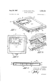
FIGURE 1 is a side perspective view of the container of this invention;
FIGURE 2 is a plan view of the outside top of the container;
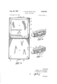
FIGURE 3 is a plan view of the inside of the top and bottom of the container;
FIGURE 4 is a longitudinal sectional view of the container in closed position;
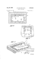
FIGURE 5 is an exploded enlarged view of the cooperating fastening portions of the top and bottom container members;
FIGURE 6 is a view of the fastening portions secured in one step;
FIGURE 7 is a view of the fastening portions showing further fastening of the same;
FIGURE 8 is an enlarged top view of the marking address portion of the container;
FIGURE 9 is an end view of the address portion of the container;
FIGURE 10 shows an address card inserted at one end of the address portion of the container and in the process of being removed by a thumb inserted within the thumb insert disposed on an opposite end.
Referring now more particularly to the drawings, in all of which like parts are designated by like reference characters, at 10 we show a record container comprising a lower section 11 and an upper section 12 hingedly secured thereto by a hinge 13 of any suitable construction. The sections 11 and 12 may be injection molded or formed in any other desired manner of a polypropylene or other suitable plastic material. It is preferred that the material 3,338,464 Patented Aug. 29, 1967 be a high impact material for protective purposes and, as shown in FIGURE 5, the external surfaces are preferably of textured leather appearance and the interior surfaces are of a smooth finish. The hinge 13 is preferably a plated brass hinge secured by aluminum rivets 14 or the like to the upper and lower sections of the container (see FIG- URES 2, 3, and 4).
The lower section 11 comprises a bottom wall 15 and an upstanding wall 16 completely surrounding the bottom wall. The said section is preferably rectangular, as shown. At each of the opposite corners adjacent the forward portion of the wall 16 an integrally formed post 17 is positioned, said post being preferably provided with a frustoconical upper end portion 18 adapted to be projected into pillars 19, 19 disposed at similarly disposed opposite corners of the cover section 12 adjacent the forward portion of the wall 25 surrounding the upper wall 27 thereof. Each of the said pillars is provided with a tapered bore 20 to receive the uppermost conical end portions 25 respectively of the posts.
As stated, the uppersection 12 of the container comprises an upper wall 27 and a surrounding wall 25 depends therefrom. The said upper or cover section 12 is preferably rectangular, as shown. It will be observed that in the form shown, the wall 25 is provided with a recess 29 extending throughout the length of the wall wherefor the recessed portion 29 of the wall 28 is adapted to be clamped over the upstanding wall 16 of the lower section and rests on an outstanding rib 16' integrally formed in the outer face of the upstanding wall 16 in the lower section 11 and extending substantially throughout its length. The rib 16' extends from a point adjacent the hinge 13 at one side of the rear portion of the wall 16 around the side portions of the wall and is interrupted briefly on either side of the forward portion of the exterior surface of the wall and then proceeds to a point adjacent and on either side of a catch 30 integrally formed, centrally located and extending forwardly of the forward portion of the wall 16. The catch 30 comprises a generally rectangular member having an elongated rectangular opening 31 therein, surrounded by a forward keeper arm 32 having a rounded protuberance 33 at either end thereof, a pair of generally triangular rearwardly disposed extensions 34 at either end thereof and an elongated rear keeper arm 35. The upper section 12 carries medially on the exterior face of its forward wall in alignment with the catch 30 a latch and keeper member 36 integrally formed with the upper section 12. Said latch and keeper member 36 comprises a fastening tab 36' protruding therefrom, the hinge line 37 permitting the tab to pivot on an edge of the top wall 27 or of an extension 27' thereof, as shown, and a latch portion 38 integrally formed therein. The latch portion 38 has an apertured flap portion 39 depending therefrom, the said flap having a U-shaped slot 40 therein. The tab 36' is provided on its lowermost edge with a peripheral outwardly projecting lip or head 70.
When the cover 12 is seated on the lower section 11, the flap 39 contacts the keeper arm 32 of the catch 30 and the flexible flap is moved outwardly thereby and snapped thereover, wherefor the arm 32 is projected through the yoke of the opening 40. The opposite ends of the keeper arms 34 are then seated in the notches 41 at the ends of the opening 40 and the arm edge 42 of the flap overlies the keeper arm 35 (FIGURE 6).
Thereafter, as shown in FIGURE 7, the tab 36' is bowed and its free end passed over the flap 39 and between the flap and the keeper arm 32 securely fastening the sections against accidental dislodgment of contents, such as records, contained or transported therein. The lip 70 of the tab 36 prevents accidental dislodgment of the tab from its engagement with the catch 30.
The top section 12 of the container is further provided with inwardly disposed guide tabs 45 integrally formed therewith and disposed on either side of said section abutting the wall 25 and spaced inwardly of the recess 29 wherefor when the cover section 12 is clamped over the lower section 11 the side portions of the wall 16 of said lower section 11 are guided by the tabs 45 into the recess 29 and lateral shifting is prevented of the respective sections. Integrally formed lugs or stops 46 are preferably formed on the outer rear face of the walls 16- and 25 and adapted to abut when the container is opened to full open position, as shown in FIGURE 3.
The top wall 27 of the upper cover section 12, is, as shown, preferably provided with a recessed rectangular panel portion 50 having an address card receptacle 51 integrally formed therein by providing the card receptacle portion of the panel with an upstanding interrupted inwardly directed rim 52 disposed on either of the longitudinal sides 53, 54 of the card pocket overlying longitudinal spaced openings in the panel on either of the opposite sides 53, 54 of the pocket. Upstanding ribs 56 are provided adjacent the side 57 of the pocket and said ribs represent an extension of the rim 52. On side 58 of the pocket a pair of parallel spaced ribs 59 generally at right angles to said side 58 are provided which act as stops with the ribs 56 to retain the card in the pocket during shipment. As shown, the rim 52 is provided with U- shaped notches 60 which overlie tongues 61 connecting the relatively depressed flat undersurface 52 of the pocket to the upwardly spaced overhanging rim 52.
The card may either be inserted from the edge 58, as shown in FIGURE 10, sliding the same over the surface 62 and over the tongues 61 under the rims until it contacts the upstanding ribs 56 at which point it will have passed the guide ribs 59 and be securely seated in the pocket and removed in reverse fashion Wherefor the card may be reversed and ready for return shipment as dictated by the opposite side of the card, or it may be inserted or removed by placing an edge of the card beneath the rim portions adjacent an edge, either 53 or 54, of the pocket, bowing the card and sliding the opposite edge thereof beneath the rim portions adjacent the opposite edge thereto.
In operation, as stated hereinbelow, it is proposed to use the container particularly for mailing records to and from the blind, hence it is essential that the container be readily available for inspection, as by postal authorities and yet be doubly secure against accidental dislodgment, further that a sightless person may readily manipulate the opening and closing and the fastening means and the address card. Hence the formation of portions of the container in such manner as to be readily locatable and operated by touch and the use of lift tabs, as shown at 80, FIGURES l and 2.
As stated, the container is particularly adapted for use by and for the blind but it is further adaptable for use as a shipping container or storage container for records or the like and index cards as well as address cards could be used in the container pocket.
Although we have described this invention in connection with a preferred embodiment, we are aware that numerous and extensive departures may be made therein without, however, departing from the spirit of this invention or the scope of the appended claims.
What we claim is:
1. A phonograph record container or the like comprising a lower section and an upper section hingedly mounted thereon said lower section and said upper section each having surrounding side walls, the side walls of the said upper section overlapping a portion of the side walls of the lower section, the walls of the said upper section having inwardly disposed guide means integrally formed therewith spaced from said walls and adapted to lap an opposite side of the walls of the lower section where by said walls are guided into nesting engagement, the
upper section having latch means integrally formed in portions of the side wall surrounding the same, the lower section having a catch integrally formed therewith, the said latch means and catch being adapted to be interlocked during nesting engagement of the sections.
2. A phonograph record container or the like as claimed in claim 1 in which said latch means has an opening therethrough and said catch projects through said opening and beyond said latch means when said latch means and catch are interlocked, said latch means having a tab hingedly mounted thereon, which tab being adapted to engage said catch beyond said latch means and further secure the sections against disengagement.
3. A phonograph record container or the like as claimed in claim 2 in which said catch has an opening thereth-rough disposed beyond said latch means when said latch means and catch are interlocked, said tab projectable through said last mentioned opening to engage said catch, said tab having a lip adjacent to the distal end thereof and extending outwardly thereof to prevent accidental withdrawal of said tab.
4. A phonograph record container or the like comprising a lower section and an upper section hingedly secured thereto, said lower section comprising a bottom wall and an upstanding side wall surrounding the bottom wall, said upper section comprising an upper wall and a depending side wall surrounding the upper wall, the side wall of the said upper section being clamped over the side wall of said lower section, the side wall of said lower section having a catch member projecting outwardly therefrom, said catch member having an open-ing therethrough, the side wall of said upper section having a latch member comprising a flap portion projecting downwardly from the side wall of said upper section, said flap being provided with an aperture, a portion of the catch member being adapted to project outwardly through the said aperture in the flap, a fastening tab hingedly mounted on an upper portion of said latch member and adapted to be disposed through the opening in said catch and to abut a lower portion of said flap member disposed below the outwardly projecting portion of said catch to securely lock the upper section to the lower section.
5. A phonograph record container or the like comprising a lower section and an upper section hingedly secured thereto, said lower section comprising a bottom wall and an upstanding side wall surrounding the bottom wall, said upper section comprising an upper wall and a depending side wall surrounding the upper wall, the depending wall having a recessed portion adapted to be clamped over the upstanding side wall of the bottom section, the side Wall of said upper section being clamped over the side wall of said lower section, the side wall of said lower section having a catch member projecting outwardly therefrom, said catch member having an opening therethrough, the side wall of said upper section having a latch member comprising a flap portion projecting downwardly from the side wall of said upper section, said flap being provided with an aperture, the said aperture seating the outwardly projecting portion of the catch therein, a fastening tab hingedly mounted on an upper portion of said latch member and adapted to be disposed through the said opening in said catch and adapted to abut a portion of the flap of the latch member to securely lock the upper section to the lower section upon which it is seated.
6. A phonograph record container or the like comprising a lower section and an upper section hingedly mounted thereon, said lower section and said upper section each having surrounding side walls, said walls having guide means integrally formed therewith whereby said walls are guided into nesting engagement, the upper section having latch means integrally formed in portions of the side wall surrounding the same, the lower section having a catch being adapted to be interlocked during nest-ing engagement of the sections, the said catch being provided with a forwardly disposed keeper arm, a rearwardly disposed keeper arm, an elongated opening between said forwardly and rearwardly disposed keeper arms, the said latch means having an apertured flap portion, the said flap portion being snapped over said forwardly disposed keeper arm and disposed to underlie the same, said forwardly disposed keeper arm having protuber-ances extending outwardly thereof preventing accidental disengagement of the latch means, flap, and catch.
7. A phonograph record container or the like comprising a lower section and an upper section hingedly mounted thereon, said lower section and said upper section each having surrounding side walls, said walls having guide means integrally formed therewith whereby said walls are guided into nesting engagement, the upper section having latch means integrally formed in portions of the side wall surrounding the same, the lower section having a catch integrally formed therewith, the said latch means and catch being adapted to be interlocked during nesting engagement of the sections, the said catch being provided with a forwardly disposed keeper arm, a rearwardly disposed keeper arm, an elongated opening between said forwardly and rearwardly disposed keeper arms, the said latch means having an ape-rtu-red flap portion, the said flap portion being snapped over the forwardly disposed keeper arm and disposed to underlie the same, said forwardly disposed keeper arm having protuherances extending outwardly thereof preventing accidental disengagement of the latch flap and catch said keeper arms being connected by angled lateral portions, the said flap aperture being a U-shaped slot, the legs of said U-shaped slot of the flap adapted to have the angled lateral portions connecting the keeper arms projected therethrough.
8. A phonograph record container or the like comprising a lower section and an upper section hingedly mounted thereon, said lower section and said upper section each having surrounding side walls, said walls having guide means integrally formed therewith whereby said walls are guided into nesting engagement, the upper section having latch means integrally formed in portions of the side wall surrounding the same, the lower section having a catch integrally formed therewith, the said latch means and catch being adapted to be interlocked during nesting engagement of the sections, the said catch being provided with a foiwardly disposed keeper arm, a rearwardly disposed keeper arm, an elongated opening between said forwardly and rearwardly disposed keeper arms, the said latch means having an apertured flap portion, the said flap portion being snapped over the forwardly disposed keeper arm and disposed to underlie the same, said forwardly disposed keeper arm having protuberances extending outwardly thereof preventing accidental disengage- :ment of the latch means, flap, and catch, a portion of said flap portion being adapted to be disposed through said opening in the catch and to further secure the nested sections.
References Cited UNITED STATES PATENTS 505,531 9/1893 Hasker 312 1,048,556- 12/1912 Mackie 229-84 3,107,783 10/ 196 3 Corey et al.
THERON E. CONDON, Primary Examiner.
JAMES B. MARBERT, Examiner.
Claims (1)
1. A PHONOGRAPH RECORD CONTAINER OR THE LIKE COMPRISING A LOWER SECTION AND AN UPPER SECTION HINGEDLY MOUNTED THEREON SAID LOWER SECTION AND SAID UPPER SECTION EACH HAVING SURROUNDING SIDE WALLS, THE SIDE WALLS OF THE SAID UPPER SECTION OVERLAPPING A PORTION OF THE SIDE WALLS OF THE LOWER SECTION, THE WALLS OF THE SAID UPPER SECTION HAVING INWARDLY DISPOSED GUIDE MEANS INTEGRALLY FORMED THEREWITH SPACED FROM SAID WALLS AND ADAPTED TO LAP AN OPPOSITE SIDE OF THE WALLS OF THE LOWER SECTION WHEREBY SAID WALLS ARE GUIDED INTO NESTING ENGAGEMENT, THE UPPER SECTION HAVING LATCH MEANS INTEGRALLY FORMED IN PORTIONS OF THE SIDE WALL SURROUNDING THE SAME, THE LOWER SECTION HAVING A CATCH INTEGRALLY FORMED THEREWITH, THE SAID LATCH MEANS AND CATCH BEING ADAPTED TO BE INTERLOCKED DURING NESTING ENGAGEMENT OF THE SECTIONS.
Priority Applications (1)
| Application Number | Priority Date | Filing Date | Title |
|---|---|---|---|
| US442932A US3338464A (en) | 1965-03-26 | 1965-03-26 | Record containers |
Applications Claiming Priority (1)
| Application Number | Priority Date | Filing Date | Title |
|---|---|---|---|
| US442932A US3338464A (en) | 1965-03-26 | 1965-03-26 | Record containers |
Publications (1)
| Publication Number | Publication Date |
|---|---|
| US3338464A true US3338464A (en) | 1967-08-29 |
Family
ID=23758747
Family Applications (1)
| Application Number | Title | Priority Date | Filing Date |
|---|---|---|---|
| US442932A Expired - Lifetime US3338464A (en) | 1965-03-26 | 1965-03-26 | Record containers |
Country Status (1)
| Country | Link |
|---|---|
| US (1) | US3338464A (en) |
Cited By (14)
| Publication number | Priority date | Publication date | Assignee | Title |
|---|---|---|---|---|
| US3415407A (en) * | 1967-03-07 | 1968-12-10 | Minnesota Mining & Mfg | Container |
| US3441128A (en) * | 1968-01-08 | 1969-04-29 | Goldberg Brothers Inc | Film reel shipping container |
| US3456781A (en) * | 1967-09-14 | 1969-07-22 | Bernard G Bradbury | Spool container |
| US4105112A (en) * | 1977-02-10 | 1978-08-08 | Howmedica Inc. | Lockable shipping box |
| US4216862A (en) * | 1979-04-23 | 1980-08-12 | Dart Industries Inc. | Children's lunch box |
| US4784508A (en) * | 1986-10-10 | 1988-11-15 | Shannon Brian M | Tabular divider sheets |
| EP0398608A3 (en) * | 1989-05-15 | 1991-06-05 | Eml Limited | Label holders |
| US5054612A (en) * | 1988-11-07 | 1991-10-08 | Meyer Jr Otto E | Facial tissue sanitary system including closure sealer |
| US5331756A (en) * | 1988-05-04 | 1994-07-26 | Rehrig International, Inc. | Basket wall with placard display assembly |
| US20030024970A1 (en) * | 2001-08-02 | 2003-02-06 | George Lonergan | Document container |
| USD491059S1 (en) | 2002-09-06 | 2004-06-08 | Sunyong Kim | Tissue box |
| US20060124479A1 (en) * | 2004-12-13 | 2006-06-15 | Osborn Warren R | Injection molded DVD case having at least one recess on an outer surface for the installation of a decorative insert |
| US20060186123A1 (en) * | 2005-02-22 | 2006-08-24 | Baltz Kyle L | Storage container |
| US20100314848A1 (en) * | 2008-01-16 | 2010-12-16 | James Edward Honiball | Advertising trolley arrangement |
Citations (3)
| Publication number | Priority date | Publication date | Assignee | Title |
|---|---|---|---|---|
| US505531A (en) * | 1893-09-26 | And william p | ||
| US1048556A (en) * | 1912-04-17 | 1912-12-31 | William Mackie | Envelop. |
| US3107783A (en) * | 1961-02-20 | 1963-10-22 | Creative Packaging Inc | Phonograph record portfolio |
-
1965
- 1965-03-26 US US442932A patent/US3338464A/en not_active Expired - Lifetime
Patent Citations (3)
| Publication number | Priority date | Publication date | Assignee | Title |
|---|---|---|---|---|
| US505531A (en) * | 1893-09-26 | And william p | ||
| US1048556A (en) * | 1912-04-17 | 1912-12-31 | William Mackie | Envelop. |
| US3107783A (en) * | 1961-02-20 | 1963-10-22 | Creative Packaging Inc | Phonograph record portfolio |
Cited By (18)
| Publication number | Priority date | Publication date | Assignee | Title |
|---|---|---|---|---|
| US3415407A (en) * | 1967-03-07 | 1968-12-10 | Minnesota Mining & Mfg | Container |
| US3456781A (en) * | 1967-09-14 | 1969-07-22 | Bernard G Bradbury | Spool container |
| US3441128A (en) * | 1968-01-08 | 1969-04-29 | Goldberg Brothers Inc | Film reel shipping container |
| US4105112A (en) * | 1977-02-10 | 1978-08-08 | Howmedica Inc. | Lockable shipping box |
| US4216862A (en) * | 1979-04-23 | 1980-08-12 | Dart Industries Inc. | Children's lunch box |
| DE3015134A1 (en) * | 1979-04-23 | 1980-10-30 | Dart Ind Inc | BREAKFAST BOX FOR CHILDREN |
| US4784508A (en) * | 1986-10-10 | 1988-11-15 | Shannon Brian M | Tabular divider sheets |
| US5331756A (en) * | 1988-05-04 | 1994-07-26 | Rehrig International, Inc. | Basket wall with placard display assembly |
| US5054612A (en) * | 1988-11-07 | 1991-10-08 | Meyer Jr Otto E | Facial tissue sanitary system including closure sealer |
| EP0398608A3 (en) * | 1989-05-15 | 1991-06-05 | Eml Limited | Label holders |
| US20030024970A1 (en) * | 2001-08-02 | 2003-02-06 | George Lonergan | Document container |
| USD491059S1 (en) | 2002-09-06 | 2004-06-08 | Sunyong Kim | Tissue box |
| USD504314S1 (en) | 2002-09-06 | 2005-04-26 | Sunyong Kim | Tissue box |
| USD514437S1 (en) | 2002-09-06 | 2006-02-07 | Sunyong Kim | Tissue box |
| US20060124479A1 (en) * | 2004-12-13 | 2006-06-15 | Osborn Warren R | Injection molded DVD case having at least one recess on an outer surface for the installation of a decorative insert |
| US20060186123A1 (en) * | 2005-02-22 | 2006-08-24 | Baltz Kyle L | Storage container |
| US8066143B2 (en) * | 2005-02-22 | 2011-11-29 | Rehrig Pacific Company | Storage container with hinged lid |
| US20100314848A1 (en) * | 2008-01-16 | 2010-12-16 | James Edward Honiball | Advertising trolley arrangement |
Similar Documents
| Publication | Publication Date | Title |
|---|---|---|
| US2747732A (en) | Shipping case and storage chest | |
| US4365711A (en) | Video cassette storage and shipping container apparatus | |
| US3186574A (en) | Receptacle with integral hinged cover and support | |
| CN110573432B (en) | Tamper-resistant bucket | |
| US5906292A (en) | Latch for container | |
| US4216862A (en) | Children's lunch box | |
| US9102446B2 (en) | Tamper evident thermoformed plastic clamshell container | |
| US4819829A (en) | Closure for pourable materials container | |
| US2522049A (en) | Carton | |
| US3415407A (en) | Container | |
| US3357630A (en) | Container | |
| US4150777A (en) | Container | |
| US2975889A (en) | Bubble package | |
| GB2137167A (en) | Containers having hinged lids | |
| US3978985A (en) | Two-piece case | |
| US3552551A (en) | Film reel shipping case | |
| US3416655A (en) | Tray-enclosed jewelry box | |
| US2663491A (en) | Case | |
| US3695481A (en) | Hinged plastic closure for sheet metal cans | |
| US3526351A (en) | Container | |
| US5411160A (en) | Child resistant closure | |
| US2731999A (en) | Protective cover device | |
| US3278009A (en) | Match container | |
| US2796190A (en) | Record container | |
| US2633285A (en) | Partitioned container with closure |