US3365232A - Sunshade assembly - Google Patents
Sunshade assembly Download PDFInfo
- Publication number
- US3365232A US3365232A US521390A US52139066A US3365232A US 3365232 A US3365232 A US 3365232A US 521390 A US521390 A US 521390A US 52139066 A US52139066 A US 52139066A US 3365232 A US3365232 A US 3365232A
- Authority
- US
- United States
- Prior art keywords
- sunshade
- legs
- support arm
- loop portions
- assembly
- Prior art date
- Legal status (The legal status is an assumption and is not a legal conclusion. Google has not performed a legal analysis and makes no representation as to the accuracy of the status listed.)
- Expired - Lifetime
Links
- 238000004873 anchoring Methods 0.000 description 1
- 230000000712 assembly Effects 0.000 description 1
- 238000000429 assembly Methods 0.000 description 1
Images
Classifications
-
- B—PERFORMING OPERATIONS; TRANSPORTING
- B60—VEHICLES IN GENERAL
- B60J—WINDOWS, WINDSCREENS, NON-FIXED ROOFS, DOORS, OR SIMILAR DEVICES FOR VEHICLES; REMOVABLE EXTERNAL PROTECTIVE COVERINGS SPECIALLY ADAPTED FOR VEHICLES
- B60J3/00—Antiglare equipment associated with windows or windscreens; Sun visors for vehicles
- B60J3/02—Antiglare equipment associated with windows or windscreens; Sun visors for vehicles adjustable in position
- B60J3/0204—Sun visors
- B60J3/0213—Sun visors characterised by the mounting means
- B60J3/0265—Attachments of sun visors to mounting means including details of sun visor bearing member regulating the rotational friction on the support arm
Definitions
- This invention relates to sunshade assemblies and more particularly to a sunshade assembly having improved means for mounting a sunshade on a support arm.
- One feature of this invention is that it provides a sunshade assembly having a preformed Wire member which includes a plurality of loops frictionally engaging a support arm and a plurality of torsion legs connected to the loops. Another feature of this invention is that the legs grip opposing sides of the sunshade and that interconnecting means interconnect successive pairs of legs through the sunshade to support the sunshade on the support arm. A further feature of this invention is that the loops and legs are formed integral with each other and that the interconnecting means are formed integral with the successive pairs of legs.
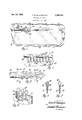
- FIGURE 1 is a partial view of a vehicle body embodying a sunshade assembly according to this invention
- FIGURE 2 is an enlarged view of a portion of FIG- URE 1;
- FIGURE 3 is a view of the assembly being mounted on the support arm
- FIGURE 4 is a sectional view taken generally along the plane indicated by line 4-4 of FIGURE 3;
- FIGURE 5 is a sectional view taken generally along the plane indicated by line 5-5 of FIGURE 3;
- FIGURE 6 is a partially broken away perspective view.
- a vehicle body designated generally 10 includes a windshield 12, the upper end of which is conventionally mounted in a body header structure, not shown, which is concealed from view by the body headlining 14.
- a sunshade assembly 16 according to this invention includes a swivel socket structure 18 which mounts a support arm 20 for both vertical and horizontal movement. Reference may be had to Keating 3,017,217 for the details of the structure 18.
- a sunshade 22 is mounted on the arm 20 by mounting means 24 according to this invention.
- the mounting means generally comprises a plurality of spaced longitudinally aligned loops 26, each of which includes a pair of offset longitudinally spaced depending legs 28.
- Each leg 28 is connected to the next successive leg 28 on the opposite side of the sunshade 22 by means of a generally S-shaped interconnecting cross leg 39.
- the intermediate portions of the cross legs 38 extend through successive openings 32 in the sunshade 22 and the lateral end portions of the legs grip opposite sides of the sunshade therebetween.
- FIGURE 3 When the mounting means and sunshade are assembled to the arm 20 by forcing the successive loops over the end of the arm, FIGURE 3, the loops 26 and legs 28 thereof are twisted relative to legs 30 about an axis transverse of the longitudinal axis of the loops so that they approach a normal relationship to their longitudinal axis.
- the legs 28 try and return the loops 26 to their normal position as shown in FIGURES 5 and 6 and thereby cause the loops to tightly and frictionally engage the periphery of the support arm 26 as can be seen by reference to FIG- URE 4.
- the depending legs 28 function as torsion rods or members while the interconnecting legs 30 function as the anchoring means for these legs so that when the mounting means and the sunshade 22 are assembled to the rod 20, the sunshade will thereafter remain in any position to which it is adjusted with respect to the arm 26-.
- this invention provides an improved sunshade support assembly.
- a vehicle body sunshade assembly comprising, a support rod adapted to be mounted on a vehicle body, a sunshade, and mounting means for mounting the sunshade on the support arm, said means including a plurality of loop portions surrounding a major portion of the periphery of the support arm, each of said loop portions including a pair of depending legs, anchor means interconnecting successive pairs of legs and gripping opposite sides of said sunshade, said successive pairs of legs functioning as torsion members twisting said loop portions about an axis transversely of the longitudinal axis thereof to cause said loop portions to frictionally engage said support arm.
Landscapes
- Engineering & Computer Science (AREA)
- Mechanical Engineering (AREA)
- Tents Or Canopies (AREA)
- Building Awnings And Sunshades (AREA)
Description
Jan. 23, 1968 o. a. BALLANTYNE 3,365,232
SUNSHADE ASSEMBLY Filed Jan. 18, 1966 I N VENTOR.
A TTORNE Y United htates 3,365,232 SUNSHADE ASSEMBLY David B. Baliantyne, Southfield', Mich, assignor to General Motors Corporation, Detroit, Mich, a corporation of Delaware Filed Jan. 18, 1966, Ser. No. 521,390 4 Claims. (Cl. 296-37) This invention relates to sunshade assemblies and more particularly to a sunshade assembly having improved means for mounting a sunshade on a support arm.
One feature of this invention is that it provides a sunshade assembly having a preformed Wire member which includes a plurality of loops frictionally engaging a support arm and a plurality of torsion legs connected to the loops. Another feature of this invention is that the legs grip opposing sides of the sunshade and that interconnecting means interconnect successive pairs of legs through the sunshade to support the sunshade on the support arm. A further feature of this invention is that the loops and legs are formed integral with each other and that the interconnecting means are formed integral with the successive pairs of legs.
These and other features of the sunshade assembly will be readily apparent from the following specification and drawings wherein:
FIGURE 1 is a partial view of a vehicle body embodying a sunshade assembly according to this invention;
FIGURE 2 is an enlarged view of a portion of FIG- URE 1;
FIGURE 3 is a view of the assembly being mounted on the support arm;
FIGURE 4 is a sectional view taken generally along the plane indicated by line 4-4 of FIGURE 3;
FIGURE 5 is a sectional view taken generally along the plane indicated by line 5-5 of FIGURE 3; and
FIGURE 6 is a partially broken away perspective view.
Referring now particularly to FIGURE 1 of the drawings, a vehicle body designated generally 10 includes a windshield 12, the upper end of which is conventionally mounted in a body header structure, not shown, which is concealed from view by the body headlining 14. A sunshade assembly 16 according to this invention includes a swivel socket structure 18 which mounts a support arm 20 for both vertical and horizontal movement. Reference may be had to Keating 3,017,217 for the details of the structure 18. A sunshade 22 is mounted on the arm 20 by mounting means 24 according to this invention.
The mounting means generally comprises a plurality of spaced longitudinally aligned loops 26, each of which includes a pair of offset longitudinally spaced depending legs 28. Each leg 28 is connected to the next successive leg 28 on the opposite side of the sunshade 22 by means of a generally S-shaped interconnecting cross leg 39. The intermediate portions of the cross legs 38 extend through successive openings 32 in the sunshade 22 and the lateral end portions of the legs grip opposite sides of the sunshade therebetween.
When the mounting means are assembled to the sunshade 22 as shown in FIGURES 2, 3 and 6, the depending offset legs 28 of each loop 26 and the end portions 3,355,232 Patented Jan. 23, 1958 of the leg 3% grip opposite sides of the sunshade 22 therebetween. It will be noted with reference to FIGURE 3 that the loops 26 of the mounting means are angularly located with respect to their longitudinal axis and the plane of the sunshade 22.
When the mounting means and sunshade are assembled to the arm 20 by forcing the successive loops over the end of the arm, FIGURE 3, the loops 26 and legs 28 thereof are twisted relative to legs 30 about an axis transverse of the longitudinal axis of the loops so that they approach a normal relationship to their longitudinal axis. The legs 28 try and return the loops 26 to their normal position as shown in FIGURES 5 and 6 and thereby cause the loops to tightly and frictionally engage the periphery of the support arm 26 as can be seen by reference to FIG- URE 4.
The depending legs 28 function as torsion rods or members while the interconnecting legs 30 function as the anchoring means for these legs so that when the mounting means and the sunshade 22 are assembled to the rod 20, the sunshade will thereafter remain in any position to which it is adjusted with respect to the arm 26-.
Thus, this invention provides an improved sunshade support assembly.
I claim:
1. A vehicle body sunshade assembly comprising, a support rod adapted to be mounted on a vehicle body, a sunshade, and mounting means for mounting the sunshade on the support arm, said means including a plurality of loop portions surrounding a major portion of the periphery of the support arm, each of said loop portions including a pair of depending legs, anchor means interconnecting successive pairs of legs and gripping opposite sides of said sunshade, said successive pairs of legs functioning as torsion members twisting said loop portions about an axis transversely of the longitudinal axis thereof to cause said loop portions to frictionally engage said support arm.
2. A sunshade assembly as recited in claim 1 wherein said sunshade includes a plurality of openings and said anchor means extends through said openings and interconnects successive pairs of legs on opposite sides of the sunshade.
3. A sunshade assembly as recited in claim 1 wherein said anchor means includes a leg extending through said sunshade and having portions thereof gripping said sunshade to each side thereof and being secured to successive pairs of legs of said loop portions.
4. A sunshade assembly as recited in claim 1 wherein said anchor means includes a generally S-shaped leg extending through said sunshade and having the end portions thereof engaging opposite sides of the sunshade, said leg, said loop portions and said depending legs being formed integral with each other.
References Cited UNITED STATES PATENTS 3,150,896 9/1964 Plattner 29697 3,333,886 8/1967 Wenger 296-97 LEO FRIAGLIA, Primary Examiner. L. D. MORRIS, Assistant Examiner.
Claims (1)
1. A VEHICLE BODY SUNSHADE ASSEMBLY COMPRISING, A SUPPORT ROD ADAPTED TO BE MOUNTED ON A VEHICLE BODY, A SUNSHADE, AND MOUNTING MEANS FOR MOUNTING THE SUNSHADE ON THE SUPPORT ARM, SAID MEANS INCLUDING A PLURALITY OF LOOP PORTIONS SURROUNDING A MAJOR PORTION OF THE PERIPHERY OF THE SUPPORT ARM, EACH OF SAID LOOP PORTIONS INCLUDING A PAIR OF DEPENDING LEGS, ANCHOR MEANS INTERCONNECTING SUCCESSIVE PAIRS OF LEGS AND GRIPPING OPPOSITE SIDES OF SAID SUNSHADE, SAID SUCCESSIVE PAIRS OF LEGS FUNCTIONING AS TORSION MEMBERS TWISTING SAID LOOP PORTIONS ABOUT AN AXIS TRANSVERSELY OF THE LONGITUDINAL AXIS THEREOF TO CAUSE SAID LOOP PORTIONS TO FRICTIONALLY ENGAGE SAID SUPPORT ARM.
Priority Applications (1)
| Application Number | Priority Date | Filing Date | Title |
|---|---|---|---|
| US521390A US3365232A (en) | 1966-01-18 | 1966-01-18 | Sunshade assembly |
Applications Claiming Priority (1)
| Application Number | Priority Date | Filing Date | Title |
|---|---|---|---|
| US521390A US3365232A (en) | 1966-01-18 | 1966-01-18 | Sunshade assembly |
Publications (1)
| Publication Number | Publication Date |
|---|---|
| US3365232A true US3365232A (en) | 1968-01-23 |
Family
ID=24076557
Family Applications (1)
| Application Number | Title | Priority Date | Filing Date |
|---|---|---|---|
| US521390A Expired - Lifetime US3365232A (en) | 1966-01-18 | 1966-01-18 | Sunshade assembly |
Country Status (1)
| Country | Link |
|---|---|
| US (1) | US3365232A (en) |
Cited By (2)
| Publication number | Priority date | Publication date | Assignee | Title |
|---|---|---|---|---|
| EP0488411A3 (en) * | 1990-11-29 | 1993-10-06 | Kabushiki Kaisha Toshiba | Hinge device for coupling a rotatable member to another member |
| US5556155A (en) * | 1994-08-03 | 1996-09-17 | Gebr. Happich Gmbh | Bearing device, in particular for pivotally mounted sun visors in vehicles |
Citations (2)
| Publication number | Priority date | Publication date | Assignee | Title |
|---|---|---|---|---|
| US3150896A (en) * | 1962-03-26 | 1964-09-29 | Andrew J Plattner | Pivotally mounted vehicle sun visor |
| US3333886A (en) * | 1965-06-22 | 1967-08-01 | Gen Motors Corp | Sunshade assembly |
-
1966
- 1966-01-18 US US521390A patent/US3365232A/en not_active Expired - Lifetime
Patent Citations (2)
| Publication number | Priority date | Publication date | Assignee | Title |
|---|---|---|---|---|
| US3150896A (en) * | 1962-03-26 | 1964-09-29 | Andrew J Plattner | Pivotally mounted vehicle sun visor |
| US3333886A (en) * | 1965-06-22 | 1967-08-01 | Gen Motors Corp | Sunshade assembly |
Cited By (2)
| Publication number | Priority date | Publication date | Assignee | Title |
|---|---|---|---|---|
| EP0488411A3 (en) * | 1990-11-29 | 1993-10-06 | Kabushiki Kaisha Toshiba | Hinge device for coupling a rotatable member to another member |
| US5556155A (en) * | 1994-08-03 | 1996-09-17 | Gebr. Happich Gmbh | Bearing device, in particular for pivotally mounted sun visors in vehicles |
Similar Documents
| Publication | Publication Date | Title |
|---|---|---|
| US4872724A (en) | Fixing device for a covering, especially a covering of a seat | |
| US3061360A (en) | Frame for car body | |
| JPH0210739B2 (en) | ||
| US3365232A (en) | Sunshade assembly | |
| CN104648313B (en) | For the clasp of vehicle safety belt | |
| US5224781A (en) | Slide for a vehicle seat comprising a device for reducing play and noise | |
| JPS6113724U (en) | Rebar tightening connector | |
| US4779928A (en) | Automotive head restraint | |
| DE1012194B (en) | Vehicle seat with suspension by sinusoidal spring straps | |
| DE19732385A1 (en) | Fastening for mounting child's seat on the back seat of a motor vehicle | |
| US3333886A (en) | Sunshade assembly | |
| DE2238216A1 (en) | SEAT FRAME | |
| DE3720450A1 (en) | VEHICLE LUGGAGE RACK | |
| EP0088489B1 (en) | Ferrule attachment | |
| EP3784523B1 (en) | Guide element comprising fastening to a seat cushion, seat cushion, vehicle seat and vehicle having a guide element of this type | |
| US2609036A (en) | Automobile seat spring | |
| US3203730A (en) | Headlining listing wire support | |
| JP2590528B2 (en) | Rear seat belt mounting structure | |
| US2851089A (en) | Lockable upholstery edge spring | |
| US3042450A (en) | Motor vehicle seat head rest | |
| DE8209355U1 (en) | UPHOLSTERY SEAT FOR A MOTOR VEHICLE | |
| US2735114A (en) | Spring assembly | |
| DE1897541U (en) | SEAT, IN PARTICULAR VEHICLE SEAT. | |
| JPH0215725Y2 (en) | ||
| US2066225A (en) | Saddle seat |