US3367006A - Heating apparatus - Google Patents
Heating apparatus Download PDFInfo
- Publication number
- US3367006A US3367006A US440376A US44037665A US3367006A US 3367006 A US3367006 A US 3367006A US 440376 A US440376 A US 440376A US 44037665 A US44037665 A US 44037665A US 3367006 A US3367006 A US 3367006A
- Authority
- US
- United States
- Prior art keywords
- yarns
- liquid
- yarn
- heating
- heater
- Prior art date
- Legal status (The legal status is an assumption and is not a legal conclusion. Google has not performed a legal analysis and makes no representation as to the accuracy of the status listed.)
- Expired - Lifetime
Links
- 238000010438 heat treatment Methods 0.000 title description 47
- 239000007788 liquid Substances 0.000 description 51
- 238000004804 winding Methods 0.000 description 7
- 238000005485 electric heating Methods 0.000 description 6
- 230000006698 induction Effects 0.000 description 4
- 239000000463 material Substances 0.000 description 4
- 230000008878 coupling Effects 0.000 description 3
- 238000010168 coupling process Methods 0.000 description 3
- 238000005859 coupling reaction Methods 0.000 description 3
- 239000003517 fume Substances 0.000 description 3
- 238000000605 extraction Methods 0.000 description 2
- 238000004519 manufacturing process Methods 0.000 description 2
- 230000007246 mechanism Effects 0.000 description 2
- 230000000717 retained effect Effects 0.000 description 2
- 229920001169 thermoplastic Polymers 0.000 description 2
- 239000004416 thermosoftening plastic Substances 0.000 description 2
- 241001635598 Enicostema Species 0.000 description 1
- 206010027626 Milia Diseases 0.000 description 1
- 239000004677 Nylon Substances 0.000 description 1
- 239000004743 Polypropylene Substances 0.000 description 1
- 229920004933 Terylene® Polymers 0.000 description 1
- 230000001154 acute effect Effects 0.000 description 1
- 230000008901 benefit Effects 0.000 description 1
- 230000008859 change Effects 0.000 description 1
- 238000004891 communication Methods 0.000 description 1
- 238000010276 construction Methods 0.000 description 1
- 238000002788 crimping Methods 0.000 description 1
- 238000005553 drilling Methods 0.000 description 1
- 230000000694 effects Effects 0.000 description 1
- 238000009413 insulation Methods 0.000 description 1
- 239000002184 metal Substances 0.000 description 1
- 229920001778 nylon Polymers 0.000 description 1
- 230000002093 peripheral effect Effects 0.000 description 1
- 239000005020 polyethylene terephthalate Substances 0.000 description 1
- -1 polypropylene Polymers 0.000 description 1
- 229920001155 polypropylene Polymers 0.000 description 1
- 230000005855 radiation Effects 0.000 description 1
- 230000004044 response Effects 0.000 description 1
- 239000010421 standard material Substances 0.000 description 1
Images


Classifications
-
- D—TEXTILES; PAPER
- D02—YARNS; MECHANICAL FINISHING OF YARNS OR ROPES; WARPING OR BEAMING
- D02J—FINISHING OR DRESSING OF FILAMENTS, YARNS, THREADS, CORDS, ROPES OR THE LIKE
- D02J13/00—Heating or cooling the yarn, thread, cord, rope, or the like, not specific to any one of the processes provided for in this subclass
- D02J13/003—Heating or cooling the yarn, thread, cord, rope, or the like, not specific to any one of the processes provided for in this subclass by contact with at least one stationary surface, e.g. a plate
-
- D—TEXTILES; PAPER
- D02—YARNS; MECHANICAL FINISHING OF YARNS OR ROPES; WARPING OR BEAMING
- D02G—CRIMPING OR CURLING FIBRES, FILAMENTS, THREADS, OR YARNS; YARNS OR THREADS
- D02G1/00—Producing crimped or curled fibres, filaments, yarns, or threads, giving them latent characteristics
- D02G1/02—Producing crimped or curled fibres, filaments, yarns, or threads, giving them latent characteristics by twisting, fixing the twist and backtwisting, i.e. by imparting false twist
- D02G1/0206—Producing crimped or curled fibres, filaments, yarns, or threads, giving them latent characteristics by twisting, fixing the twist and backtwisting, i.e. by imparting false twist by false-twisting
- D02G1/0266—Producing crimped or curled fibres, filaments, yarns, or threads, giving them latent characteristics by twisting, fixing the twist and backtwisting, i.e. by imparting false twist by false-twisting false-twisting machines
-
- D—TEXTILES; PAPER
- D02—YARNS; MECHANICAL FINISHING OF YARNS OR ROPES; WARPING OR BEAMING
- D02J—FINISHING OR DRESSING OF FILAMENTS, YARNS, THREADS, CORDS, ROPES OR THE LIKE
- D02J13/00—Heating or cooling the yarn, thread, cord, rope, or the like, not specific to any one of the processes provided for in this subclass
Definitions
- the invention relates to apparatus for heating a plurality of yarns and particularly to apparatus for heating a plurality of synthetic yarns in apparatus for treating said yarns, for example in false twisting apparatus.
- the yarn In some kinds of apparatus for treating yarn it is usual for the yarn to be continuously drawn past or through a heating zone. Where a plurality of yarns are to be treated simultaneously it is desirable that all the yarns should be heated by the same amount so that they may all have the same characteristics. Further, where a plurality of yarns are simultaneously treated on opposite sides of an apparatus it is desirable that the yarns treated on opposite sides should have the same characteristics.
- a heater in contact with which the yarns are caused to travel, the heater comprising a pair of hollow bodies spaced apart and extending lengthwise along the apparatus and interconnected at their-ends, and means for circulating a hot liquid through said hollow bodies at high velocity such that a turbulent flow is created within the hollow bodies whereby substantially the same temperature is maintained throughout both the hollow bodies.
- means for heating the liquid is disposed within the hollow bodies.
- apparatus for false twisting a plurality of synthetic yarns comprising a plurality of false twisting means disposed on opposite sides of the apparatus, a hollow body disposed on each side of the apparatus, each said hollow body having at least one surface with which yarns contact prior to passing to the false twisting means, the ends of said hollow bodies being interconnected to form a substantially closed circuit, means for circulating liquid through said closed circuit, and means for heating the liquid, the arrangement being such that in use the rate of circulation of said liquid is sufiiciently high to heat the whole of said surfaces to substantially the same temperature.
- the means for circulating the liquid can be located within the closed circuit in the path of flow of said liquid; this means may comprise an axial flow pump.
- the axial flow pump may be driven by an induction motor, the armature of which is enclosed within said closed circuit or an extension thereof; in this way the heat created in the armature windings is passed to the liquid.
- the motor may be adapted to drive said pump through a flexible coupling.
- the field windings of said motor may be disposed about the exterior of said closed circuit or of said extension thereof.
- the motor may be a 3 phase motor, and may, for example, operate at 15 v.
- Temperature sensitive means for controlling the temperature of said liquid can be included in the apparatus, and preferably the temperature sensitive means is located within the path of flow of the liquid.
- the means for heating the liquid is located within the path of flow of the liquid within the closed circuit, anw may comprise one or more electric heating elements.
- the apparatus includes a plurality of electric heating elements, the major part of the heat requirements of the system can be provided by heating elements energised independently of said temperature sensitive means, the minor part of said heat requirements being provided by heating elements controlled by said temperature sensitive means.
- An expansion vessel for the liquid can be connected to said hollow bodies and is preferably arranged above them.
- the liquid can be a non-carbonising oil of low vapour pressure.
- the surfaces of said hollow bodies which the yarns are arranged to contact may be smooth, or may be provided with a plurality of grooves along which the yarns are caused to travel. Each surface can be convexly curved in a direction oblique to the direction of travel of the yarn over it.
- each yarn across the surface of either hollow body can be oblique to the direction of flow of the liquid through that hollow body.
- the direction of travel of 'the yarn may be varied to vary the distance travelled by the yarns in contact with either surface.
- all the yarns passing over one of said hollow bodies do so in substantially parallel paths as do the yarns passing over the other said hollow body; the substantially parallel yarn paths over said one hollow body may be transverse or skew to the substantially parallel yarn paths over said other hollow body.
- all the heated surfaces of the heater that are contacted by the yarns are at approximately the same height from the ground and extend in a substantially horizontal direction.
- these surfaces may extend in their longitudinal direction substantially horizontally along each side of the apparatus, these surfaces in their transverse direction preferably extend in a generally vertical direction, or at an acute angle thereto.
- apparatus for heating a plurality of yarns wherein the yarn is passed in contact with a body heated by a hot liquid flowing in a closed circuit therein, the liquid being heated at one or more zones in its flow around said closed circuit, the temperature rise of the liquid on passing said zone or one of said zones being less than 5 C. and preferably less than 1 C.
- apparatus for heating a plurality of yarns comprising a hollow chamber in contact with at least one face of which the yarns are caused to travel, means for circulating a liquid through said hollow chamber at such a rate that a turbulent flow is created within the hollow chamber, heating means within said hollow chamber to heat the liquid and temperature sensitive means to control said heating means and maintain the temperature of the liquid to within i1%, the heating means being so arranged in relation to the rate of flow of liquid and the configuration of the hollow chamber that the temperature rise of the liquid passing over said heating means is less than 1%, whereby the temperature of the liquid throughout the hollow chamber is maintained within 1%.
- the means for circulating the liquid has a capacity relative to the quantity of liquid in the hollow chamber such that the liquid is caused to flow therethrough at a rate greater than 1.0 foot per second.
- the hollow chamber can comprise a pair of hollow bodies interconnected at their ends to form a substantially closed circuit, each of said hollow bodies having at least one face in contact with which yarns are caused to travel; the heating means can be located within said hollow bodies and the heating means can comprise one or more electric elements.
- the major part of the heat requirements of the system can be provided by heating elements energised independently of the temperature sensitive means, the minor part of said heat requirements being provided by heating elements controlled by the temperature sensitive means.
- the means for circulating the liquid can be an axial flow pump located Within the path of the liquid through said hollow chamber.
- Baflles can be included within the path of flow of the liquid through the hollow chamber to assist in creating turbulence and intermixing of the liquid.
- the hollow bodies can each comprise a plurality of sections joined together.
- Each section can be provided with flanges at each end thereof, the area of the opening in said flanges being less than the area of the section adjacent thereto so as to provide a bafiie within the path of flow of the liquid.
- the baffles can extend into the hollow bodies from the face in contact with which the yarns travel.
- Means can also be included for causing a current of air to flow over the faces of the hollow chamber in contact with which the yarns travel.
- the current of air can flow across said faces in a generally upward direction.
- the means'for causing the current of air can comprise a duct extending around the apparatus and provided with portions disposed adjacent and co-extensive with said faces, and means for creating a partial vacuum within said duct.
- the synthetic yarns to be treated by apparatus according to the invention can be thermo-plastic yarns, or yarns having a thermo-plastic component, for example, yarns of nylon, polypropylene, or Terylene.
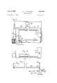
- FIGURE 1 is a side elevation of part of a false twist apparatus according to the invention.
- FIGURE 2 is a section on the line IIII in FIGURE 1 of the heater
- FIGURE 3 is a plan view of the heater
- FIGURE 4 is a side elevation of the heater viewed in the same direction as in FIGURE 1;
- FIGURE 5 is a plan view of the heater similar to FIGURE 3 showing an alternative arrangement of the heating elements and control means;
- FIGURE 6 is a plan view of a heater according to another embodiment of the invention with parts broken away and all the insulation removed to show the construction more clearly;
- FIGURE 7 is a side elevation in the direction of arrow VII in FIGURE 6 of one of the sections comprising the heater shown in FIGURE 6;
- FIGURE 8 is an end elevation of the section shown in FIGURE 7, and
- FIGURE 9 is a sectional elevation on the line IXIX of FIGURE 6 showing false twist means.
- the false twisting apparatus as shown in FIGURE 1 comprises a number of supply bobbins 1 of yarn arranged at the top of the apparatus, the yarn 2 passing downwards from each bobbin through a pair of feed rollers indicated diagrammatically at 3.
- the yarn then passes obliquely across a face 4 of a heater 5, the direction of travel of the yarn being determined by pairs of guides 6 and 7 on opposite sides of the face 4.
- From the heater the yarn passes downwardly through a false twisting head 8 and thence through feed rollers 9 and a reciprocating guide 10 of a traverse mechanism to be wound into a package 11 rotated at a constant peripheral speed by a roller 11a.
- the false twisting heads and associated mechanisms are arranged on both sides of the apparatus.
- the faces 4 of the heater 5 are convexly curved and inclined to the vertical, the guides 6 and 7 being slightly set back from the faces 4 so that the yarns are retained in contact therewith.
- the heater 5, as shown in more detail in FIGURE 3, comprises two enclosed passages 13 and 14 which extend lengthwise along the apparatus, each of said passages having a convex face 4 as hereinbefore described.
- Passages 15 and 16 connect the passages 13 and 14 at their ends, the four passages together forming a closed circuit, the general plane of the closed circuit being horizontal.
- the passages are completely covered apart from the two faces 4 with which the yarn contacts, by suitable lagging 12, although the faces 4 project proud of the lagging 12 as shown in FIGURE 2.
- An expansion vessel 17 is located above the level of said closed circuit and is connected thereto by a pipe 18 (see FIGURE 4).
- An axial flow pump 19 is located within the passage 13 and arranged to be driven by an induction motor 21.
- the shaft 22 of the pump 19 is journalled at one end in a support 20 in the passage 13, and connected at the other end by a flexible coupling 23 to the motor 21.
- the armature windings 24 of the induction motor 21 are disposed within a compartment 25 forming an extension of the closed circuit formed by the passages .13, 14, 15 and 16, the field windings 26 of the motor 21 being disposed around the outside of the compartment 25.
- Electric heating elements 27 and 28 extend into the passages 13 and 14 at opposite ends thereof, and are brought into circuit with a source of supply, and disconnected therefrom, by control means 29 operated by a heat responsive element 30 located within the closed circuit.
- the passages 13, 14, 15 and 16 forming the closed circuit are filled with a liquid, preferably a non-carbonising oil of low vapour pressure such as is sold under the trade name Voluta 45, the oil extending up the pipe 18 and partially filling the expansion vessel 17.
- the axial flow pump 19 promotes a flow of oil throughout the closed circuit, the how being at such a rate in relation to the capacity and configuration of the closed circuit that a high turbulence of the oil is created.
- the oil is heated by the electric heating elements 27 and 28, the heat responsive element 30 causing the control means 29 to disconnect the electric elements from their source of supply at a predetermined oil temperature and to reconnect the electric elements to their source of supply as the oil temperature falls.
- the temperature rise of the oil as it passes either of theheating elements 27 or 28 can be less than 5 C. and preferably in the order of 1 C., which means that the temperature throughout the closed circuit is maintained constant to within 5 C. or less and preferably to within 1 C.
- the electric heating elements can be arranged as shown in FIGURE 5 so that one or more elements 27 supplies the major part of the heat requirements of the system and a further element or elements 28 supplies the minor part of the heat requirements of the system.
- the elements 27 supplying the major part of the heat requirements can be maintained in circuit for substantially the whole time of operation, and only the elements 28 supplying the minor part of the heat requirements need be controlled by the control means 29. In this way the fluctuations in power consumption and wear on the control means 29, the control means 29 then operating at a lower loading, are both reduced.
- the surfaces 4 of the heater 5 are preferably smooth as shown but they can be provided with grooves along and in which the yarns are caused to travel.
- the guide means 6 and 7 on opposite sides of each surface 4 may be so disposed and in suflicient numbers that, by appropriately engaging the various yarns with them, the distance travelled by the yarn over the heated surface and hence the length of yarn in contact with the heated surface may be varied. In this way, and by controlling the temperature of the heater, the required crimp can be set in yarns travelling at various speeds and having various setting temperatures or requirements.
- the motor can be operated at low voltage, for example 15 volts, and preferably on 3 phase supply.
- the motor arrangement as shown and described with the armature windings fully submerged in oil within the closed extension 25 is particularly advantageous as it eliminates a possible source of oil leakage from the system and heat generated in the armature windings is transferred to the oil.
- the flexible coupling 23 is included in the drive shaft 22 to the pump 19 to allow for any distortion of the apparatus as the oil is heated to the working temperature.
- a heater as shown in FIGURES 3 and 4 having a closed circuit length of flow of oil of 25 feet, 20 gallons oil capacity, and the axial flow pump having a capacity of 60 gallons per minute was constructed.
- the electric heating elements were disposed at opposite corners of the circuit and connected to a source of supply as shown in FIGURE 5; each face 4 was four inches wide.
- the oil was heated to 240 C. and circulated around the closed circuit three times per minute, and therefore a velocity of 1.25 feet per second.
- the temperature was maintained constant through the closed circuit (and so over the surfaces 4), to an accuracy of 1 C.
- the enclosed passages on which are provided the convex heating faces 4 may conveniently be formed from .4. number of sections, particularly when the total length of each passage is required to be more than about feet long, in order to facilitate manufacture and erection.
- FIGURES 6, 7 and 8 One such embodiment is shown in FIGURES 6, 7 and 8 in which a section 34 is formed to the required shape from sheet metal to each end of which are secured flanges 35' and 36.
- Four holes 37 are provided in each flange whereby adjacent sections are bolted together by nuts and bolts 57. In order that the flanges do not interfere with the travel of the yarns in contact with the heated surface the flanges are shaped to conform to the curvature of the surface 4.
- the opening 38 in the flange is smaller than the bore of the section 34, a part 39 of the flange extending inwards across the bore of the passage from the face 4 and forming a bafile within the passage.
- a bleed screw 40 is threadably mounted within the flange 36 and communicates through drillings 41, 42 with the inside of the passageway.
- a bleed screw can be provided on one or both of the flanges of a section.
- a number of sections are bolted together to form a pair of hollow enclosed passages and their ends interconnected by conduits 43 and 44 as shown in FIGURE 6.
- conduit 44 Connected to conduit 44 by a pipe 45 is an expansion vessel 46 disposed above the level of the closed circuit, and through which oil or other liquid can be introduced into the closed circuit.
- A-ir trapped within the sections 34 by the batfles 39 can be released through the bleed screws 40.
- Mounted on an extension 47 of the conduit 43 is a motor 48 which is connected to an axial flow pump located within the conduit 49 as shown in FIGURE 3.
- the motor 48 is of the type in which the armature operates within a closed chamber in communication with the closed circuit, the field windings being arranged around and outside of the chamber. This ararngement obviates the need to provide a seal around a rotating drive shaft.
- a plurality of heating eiements 5'0 and 51 are mounted on plates 52 and 53 respectively which are secured to flanges 54, 55, formed on extensions to the conduits 43 and 44 by nuts 56. The elements extend beyond the conduit 43 and 44 and into the passages 34.
- baflles 39 assist in creating turbulence and intermixing of the oil so that a layer of cooled oil is not allowed to form adjacent the inside surface of the face 4.
- this extraction means may be arranged to cause a current of air to be drawn over the heated surface gathering at least a part of the fumes and exhausting them in the open air at any convenient point.
- the extraction means as shown in FIGURES 6 and 9 comprises a duct 31 which extends along the machine adjacent the heater.
- the top of the duct is provided with a number of holes 32 which communicate with a collector 33 secured to the top of the duct and of suitable shape so as to have its open end adjacent the top of the heated surface.
- the edge of the collector is cut away at 58 to provide clearance for yarn to pass around guides 6.
- Air is exhausted from the duct 31 by a centrifugal fan 59 through a ventilating chimney 60 to the outside air.
- the fan creates a partial vacuum within the duct 31 causing air to flow across the heated surface 4 in a generally upward direction into the collector 33 through the holes 32 and into the duct, the current of air taking with it at least some of the fumes given off by the heated yarn.
- a heater was constructed as shown in FIGURES 6 to 9 in which each of the passages comprised nine sections 34, each 5 feet long, bolted together to provide heating surfaces 4 both feet long.
- the length of the conduits 43 and 44 were 4 feet and 3 feet respectively giving a total closed circuit length of 97 feet.
- the capacity of the circuit was 45 gallons of oil which was Voluta 45 and the axial flow pump operated at the rate of gallons per minute. The oil therefore flowed at 1.8 feet per second.
- Twelve heating elements were employed each of 1950 watts, grouped equally at opposite corners of the heater as shown in FIGURE 6, the oil being heated to 235 C. Two heating elements at each corner were controlled in response to the temperature of the oil.
- the temperature of the heater surfaces 4 was maintained to within an accuracy of 1 C. at all points around the heater.
- each yarn on each side of the apparatus is subjected to the same heat treatment. Should for any reason there be a change in the temperature of the heater, then all the yarns would be affected in the same way.
- all the packages of yarn taken off the machine at any one time will, so far as any variations due to heating are concerned, contain crimped yarns all having the same characteristics. Consequently, if one package is of acceptable standard of crimped yarn, then all the other packages removed at that time should be acceptable; whilst if one package is of substandard yarn, then all the other packages should be substandard. This is particularly advantageous because if one set of packages of yarn are used to fabricate material and after dyeting etc. it is apparent that the yarn is sub-standard, then no good yarn has been wasted in the sub-standard material produced.
- the illustrated apparatus has the advantage that either all the packages of crimped yarn produced at one time will be acceptable or all can be rejected as sub-standard and consequently the risk of wasting acceptable yarn by fabricating it with unacceptable yarn is reduced or even substantially eliminated.
- the heater system has been described with reference to a conventional false twist crimping apparatus it is within the scope of the invention to incorporate the heater within any apparatus wherein synthetic yarns are subjected to heat treatment.
- Apparatus for heating a plurality of yarns comprising a continuous closed circuit formed by a pair of hollow passages spaced apart and extending parallel with each other, each of said hollow passages having at least one face in contact with which yarns can travel, with conduits joining adjacent ends of said hollow passages, one of said conduits being provided with an extension, driving means secured to said extension, pump means located within the conduit and adapted to be driven by said driving means to circulale a liquid around the closed circuit, and a plurality of heating elements disposed within the closed circuit to heat the liquid as it travels around said closed circuit.
- hollow passages are formed from a plurality of hollow sections, each of said sections comprising a hollow chamber having at least one surface over and in contact with which yarns can travel, and flanges secured to both ends of said chamber whereby a number of said sections can be joined together to form a continuous hollow passage.
- Apparatus according to claim 2 including a plurality of yarn guide means disposed on both sides of and adjacent each of said surfaces the direction of travel of yarns across the surfaces being transverse to the direction of flow of the liquid and being retained in contact with the surfaces by said guide means.
- Apparatus according to claim 1 including means for causing a current of air to flow across said surfaces of the heater comprising a duct, means for creating a partial vacuum within said duct and portions of said duct disposed adjacent and co-extensive with said surfaces.
- a heater in contact with which the yarns are caused to travel, the heater comprising a pair of hollow bodies disposed one on each side of the apparatus and interconnected at their ends by passages to form a closed circut, means within the closed circuit for circulating a liquid around the said circuit at a rate such as to cause a turbulent flow of liquid, and one or more heating means located within the closed circuit and arranged to heat the liquid by less than 1 C. in its passage thereover.
- Apparatus in accordance with claim 5 wherein there is further included a plurality of false twisting means arranged to impart a twist to the yarn as they travel in contact with said heater.
- a heater for use in apparatus for the treatment of a plurality of yarns on both sides of the apparatus comprising a closed circuit formed by a number of hollow chambers, the closed circuit extending lengthwise along both sides of the apparatus and having at least one face on each side of the machine in contact with which the yarns pass, circulating means located within one of said hollow chambers to cause a flow of liquid around said closed circuit and heating means located within the closed circuit in the path of fiow of the liquid.
- a heater according to claim 8 in which said faces of the hollow chambers in contact with which the yarns pass have a long dimension extending in a substantially horizontal direction and a short dimension in a direction perpendicular to said long dimension, the direction of travel of the yarns across said faces being transverse to the long dimension.
- Apparatus for heating a plurality of travelling yarns comprising a pair of hollow passages of substantial length in relation to their width, each of said hollow passages comprising a number of hollow chambers each having a surface in contact with which the yarns travel and a flange at each end whereby said chambers are joined together, the flanges having portions extending within the hollow passages, conduit means interconnecting the ends of said hollow passages to form a continuous circuit, a liquid contained within the continuous circuit, liquid circulating means disposed Within the continuous circuit and heating means disposed within the continuous circuit for heating the liquid at at least two locations, said locations and said heating means being arranged so that the temperature rise of the liquid passing said locations is less than 1% whereby the temperature of the liquid throughout the continuous circuit is maintained within 1%.
- Apparatus according to claim 10 including a plurality of guide means adjacent the edges of said surfaces the guide means adjacent one edge of the surfaces cooperating with the guide mcans adjacent the opposite edges of the surfaces to define paths of travel of the yarns in a substantially lengthwise direction along the surfaces and across the width thereof.
- Apparatus according to claim 10 including temperature sensitive means disposed within the continuous circuit and adapted to control at least one of said heating means, which heating means supply the minor part of the heat requirements, the major part of the heat requirements being supplied by heating elements independently of said temperature sensitive means.
Landscapes
- Engineering & Computer Science (AREA)
- Textile Engineering (AREA)
- Mechanical Engineering (AREA)
- Yarns And Mechanical Finishing Of Yarns Or Ropes (AREA)
Applications Claiming Priority (1)
| Application Number | Priority Date | Filing Date | Title |
|---|---|---|---|
| GB21932/64A GB1098135A (en) | 1964-05-27 | 1964-05-27 | Yarn heating apparatus |
Publications (1)
| Publication Number | Publication Date |
|---|---|
| US3367006A true US3367006A (en) | 1968-02-06 |
Family
ID=10171229
Family Applications (1)
| Application Number | Title | Priority Date | Filing Date |
|---|---|---|---|
| US440376A Expired - Lifetime US3367006A (en) | 1964-05-27 | 1965-03-17 | Heating apparatus |
Country Status (6)
| Country | Link |
|---|---|
| US (1) | US3367006A (de) |
| CH (1) | CH438565A (de) |
| DE (1) | DE1660415B2 (de) |
| ES (1) | ES313730A1 (de) |
| FR (1) | FR1455893A (de) |
| GB (1) | GB1098135A (de) |
Cited By (5)
| Publication number | Priority date | Publication date | Assignee | Title |
|---|---|---|---|---|
| US3482384A (en) * | 1967-12-13 | 1969-12-09 | Turbo Machine Co | Friction twisting apparatus |
| US3491524A (en) * | 1967-02-17 | 1970-01-27 | Nippon Rayon Kk | Apparatus for false twisting filaments of thermoplastics fibers |
| US3581455A (en) * | 1968-01-19 | 1971-06-01 | Eric Thomas Scriven | Machines for the heat treatment of textile yarns |
| US4115985A (en) * | 1976-07-12 | 1978-09-26 | Asa S.A. | Method of apparatus for the thermal treatment of textiles articles |
| US4176712A (en) * | 1972-02-14 | 1979-12-04 | Fiber Industries, Inc. | Yarn heating apparatus and process |
Citations (4)
| Publication number | Priority date | Publication date | Assignee | Title |
|---|---|---|---|---|
| US2089240A (en) * | 1935-06-04 | 1937-08-10 | Celanese Corp | Manufacture and use of textile materials |
| US2864229A (en) * | 1957-06-05 | 1958-12-16 | Universal Winding Co | Apparatus for thermally processing yarns |
| US2874410A (en) * | 1954-06-30 | 1959-02-24 | Du Pont | Apparatus for uniformly drawing a plurality of filaments |
| US2977745A (en) * | 1958-05-13 | 1961-04-04 | Hudson Hosiery Company | Method of and apparatus for treating textile strands |
-
1964
- 1964-05-27 GB GB21932/64A patent/GB1098135A/en not_active Expired
-
1965
- 1965-03-17 US US440376A patent/US3367006A/en not_active Expired - Lifetime
- 1965-05-18 FR FR17446A patent/FR1455893A/fr not_active Expired
- 1965-05-18 CH CH691465A patent/CH438565A/de unknown
- 1965-05-26 ES ES0313730A patent/ES313730A1/es not_active Expired
- 1965-05-28 DE DE1660415A patent/DE1660415B2/de active Pending
Patent Citations (4)
| Publication number | Priority date | Publication date | Assignee | Title |
|---|---|---|---|---|
| US2089240A (en) * | 1935-06-04 | 1937-08-10 | Celanese Corp | Manufacture and use of textile materials |
| US2874410A (en) * | 1954-06-30 | 1959-02-24 | Du Pont | Apparatus for uniformly drawing a plurality of filaments |
| US2864229A (en) * | 1957-06-05 | 1958-12-16 | Universal Winding Co | Apparatus for thermally processing yarns |
| US2977745A (en) * | 1958-05-13 | 1961-04-04 | Hudson Hosiery Company | Method of and apparatus for treating textile strands |
Cited By (5)
| Publication number | Priority date | Publication date | Assignee | Title |
|---|---|---|---|---|
| US3491524A (en) * | 1967-02-17 | 1970-01-27 | Nippon Rayon Kk | Apparatus for false twisting filaments of thermoplastics fibers |
| US3482384A (en) * | 1967-12-13 | 1969-12-09 | Turbo Machine Co | Friction twisting apparatus |
| US3581455A (en) * | 1968-01-19 | 1971-06-01 | Eric Thomas Scriven | Machines for the heat treatment of textile yarns |
| US4176712A (en) * | 1972-02-14 | 1979-12-04 | Fiber Industries, Inc. | Yarn heating apparatus and process |
| US4115985A (en) * | 1976-07-12 | 1978-09-26 | Asa S.A. | Method of apparatus for the thermal treatment of textiles articles |
Also Published As
| Publication number | Publication date |
|---|---|
| CH438565A (de) | 1967-06-30 |
| DE1660415B2 (de) | 1975-07-03 |
| FR1455893A (fr) | 1966-10-21 |
| ES313730A1 (es) | 1966-02-16 |
| DE1660415A1 (de) | 1970-07-16 |
| GB1098135A (en) | 1968-01-03 |
Similar Documents
| Publication | Publication Date | Title |
|---|---|---|
| US2682116A (en) | Method and apparatus for treating fibrous sheet material by superheated steam or vapors | |
| US3599447A (en) | Apparatus for treating textile materials with a treating liquid | |
| US3367006A (en) | Heating apparatus | |
| US5189810A (en) | Methods and apparatus for the continuous heat treating of yarn | |
| US2958921A (en) | Heat treatment of thermoplastic or thermosetting yarn | |
| US6041587A (en) | Machine for making a mixed yarn by combining two false-twist textured yarns | |
| US3501904A (en) | Process and machine for the texturization of thermoplastic yarn,and the yarn thus obtained | |
| US3368335A (en) | Apparatus for the treatment of yarns | |
| US2083141A (en) | Apparatus for conditioning sheet material | |
| KR100613898B1 (ko) | 텐터기의 열풍공급 분배구조 | |
| US4227317A (en) | Apparatus for the heat treatment of textiles | |
| US3302304A (en) | Apparatus for ventilating webs of textile material | |
| US2772486A (en) | Apparatus for conditioning, preferably drying, of a web-like material | |
| US2499142A (en) | Heat setting of textile fabrics | |
| US5014380A (en) | Process and installation for heat treatment of textile threads | |
| US2101301A (en) | Method and apparatus for drying cellulose and like material in a continuous web | |
| US2499141A (en) | Heat-treatment of webs of textile materials | |
| US3979930A (en) | Method and an apparatus for treating textile materials | |
| EP0900866B1 (de) | Heizanordnung | |
| JP7033881B2 (ja) | 合成糸用の冷却装置 | |
| US5191725A (en) | Venting system for heat treating flat material webs | |
| US3362087A (en) | Dryers for carpets and the like | |
| US3397465A (en) | Heat shrinking apparatus | |
| US1374335A (en) | Apparatus for drying metal strips | |
| US6139588A (en) | Processing textile structures |