US3400640A - Method and apparatus for folding and locking a box blank - Google Patents
Method and apparatus for folding and locking a box blank Download PDFInfo
- Publication number
- US3400640A US3400640A US569003A US56900366A US3400640A US 3400640 A US3400640 A US 3400640A US 569003 A US569003 A US 569003A US 56900366 A US56900366 A US 56900366A US 3400640 A US3400640 A US 3400640A
- Authority
- US
- United States
- Prior art keywords
- panel
- locking
- plunger
- panels
- folding
- Prior art date
- Legal status (The legal status is an assumption and is not a legal conclusion. Google has not performed a legal analysis and makes no representation as to the accuracy of the status listed.)
- Expired - Lifetime
Links
- 238000000034 method Methods 0.000 title description 8
- 210000002105 tongue Anatomy 0.000 description 22
- 238000005452 bending Methods 0.000 description 6
- 230000000994 depressogenic effect Effects 0.000 description 2
- 210000005069 ears Anatomy 0.000 description 2
- 239000011087 paperboard Substances 0.000 description 2
- 240000005020 Acaciella glauca Species 0.000 description 1
- 230000000295 complement effect Effects 0.000 description 1
- 230000001143 conditioned effect Effects 0.000 description 1
- 230000000694 effects Effects 0.000 description 1
- 239000003292 glue Substances 0.000 description 1
- 230000007246 mechanism Effects 0.000 description 1
- 238000012986 modification Methods 0.000 description 1
- 230000004048 modification Effects 0.000 description 1
- 235000003499 redwood Nutrition 0.000 description 1
- 230000000452 restraining effect Effects 0.000 description 1
Images


Classifications
-
- B—PERFORMING OPERATIONS; TRANSPORTING
- B65—CONVEYING; PACKING; STORING; HANDLING THIN OR FILAMENTARY MATERIAL
- B65D—CONTAINERS FOR STORAGE OR TRANSPORT OF ARTICLES OR MATERIALS, e.g. BAGS, BARRELS, BOTTLES, BOXES, CANS, CARTONS, CRATES, DRUMS, JARS, TANKS, HOPPERS, FORWARDING CONTAINERS; ACCESSORIES, CLOSURES, OR FITTINGS THEREFOR; PACKAGING ELEMENTS; PACKAGES
- B65D5/00—Rigid or semi-rigid containers of polygonal cross-section, e.g. boxes, cartons or trays, formed by folding or erecting one or more blanks made of paper
- B65D5/20—Rigid or semi-rigid containers of polygonal cross-section, e.g. boxes, cartons or trays, formed by folding or erecting one or more blanks made of paper by folding-up portions connected to a central panel from all sides to form a container body, e.g. of tray-like form
- B65D5/30—Rigid or semi-rigid containers of polygonal cross-section, e.g. boxes, cartons or trays, formed by folding or erecting one or more blanks made of paper by folding-up portions connected to a central panel from all sides to form a container body, e.g. of tray-like form with tongue-and-slot or like connections between sides and extensions of other sides
- B65D5/301—Rigid or semi-rigid containers of polygonal cross-section, e.g. boxes, cartons or trays, formed by folding or erecting one or more blanks made of paper by folding-up portions connected to a central panel from all sides to form a container body, e.g. of tray-like form with tongue-and-slot or like connections between sides and extensions of other sides the tongue being a part of a lateral extension of a side wall
- B65D5/302—Rigid or semi-rigid containers of polygonal cross-section, e.g. boxes, cartons or trays, formed by folding or erecting one or more blanks made of paper by folding-up portions connected to a central panel from all sides to form a container body, e.g. of tray-like form with tongue-and-slot or like connections between sides and extensions of other sides the tongue being a part of a lateral extension of a side wall combined with a slot provided in an adjacent side wall
-
- B—PERFORMING OPERATIONS; TRANSPORTING
- B31—MAKING ARTICLES OF PAPER, CARDBOARD OR MATERIAL WORKED IN A MANNER ANALOGOUS TO PAPER; WORKING PAPER, CARDBOARD OR MATERIAL WORKED IN A MANNER ANALOGOUS TO PAPER
- B31B—MAKING CONTAINERS OF PAPER, CARDBOARD OR MATERIAL WORKED IN A MANNER ANALOGOUS TO PAPER
- B31B50/00—Making rigid or semi-rigid containers, e.g. boxes or cartons
- B31B50/26—Folding sheets, blanks or webs
- B31B50/44—Folding sheets, blanks or webs by plungers moving through folding dies
- B31B50/46—Folding sheets, blanks or webs by plungers moving through folding dies and interconnecting side walls
- B31B50/48—Folding sheets, blanks or webs by plungers moving through folding dies and interconnecting side walls by folding or tucking in locking flaps
- B31B50/50—Folding sheets, blanks or webs by plungers moving through folding dies and interconnecting side walls by folding or tucking in locking flaps by interengaging tongues and slots
-
- B—PERFORMING OPERATIONS; TRANSPORTING
- B31—MAKING ARTICLES OF PAPER, CARDBOARD OR MATERIAL WORKED IN A MANNER ANALOGOUS TO PAPER; WORKING PAPER, CARDBOARD OR MATERIAL WORKED IN A MANNER ANALOGOUS TO PAPER
- B31B—MAKING CONTAINERS OF PAPER, CARDBOARD OR MATERIAL WORKED IN A MANNER ANALOGOUS TO PAPER
- B31B50/00—Making rigid or semi-rigid containers, e.g. boxes or cartons
- B31B50/26—Folding sheets, blanks or webs
- B31B50/44—Folding sheets, blanks or webs by plungers moving through folding dies
- B31B50/46—Folding sheets, blanks or webs by plungers moving through folding dies and interconnecting side walls
-
- B—PERFORMING OPERATIONS; TRANSPORTING
- B31—MAKING ARTICLES OF PAPER, CARDBOARD OR MATERIAL WORKED IN A MANNER ANALOGOUS TO PAPER; WORKING PAPER, CARDBOARD OR MATERIAL WORKED IN A MANNER ANALOGOUS TO PAPER
- B31B—MAKING CONTAINERS OF PAPER, CARDBOARD OR MATERIAL WORKED IN A MANNER ANALOGOUS TO PAPER
- B31B50/00—Making rigid or semi-rigid containers, e.g. boxes or cartons
- B31B50/60—Uniting opposed surfaces or edges; Taping
- B31B50/73—Uniting opposed surfaces or edges; Taping by mechanically interlocking integral parts, e.g. by tongues and slots
- B31B50/732—Uniting opposed surfaces or edges; Taping by mechanically interlocking integral parts, e.g. by tongues and slots by folding or tucking-in locking flaps
- B31B50/734—Uniting opposed surfaces or edges; Taping by mechanically interlocking integral parts, e.g. by tongues and slots by folding or tucking-in locking flaps interengaging tongues and slots
Definitions
- the interlocking members comprise a locking tab extending from the side edge of one wall panel which is slit diagonally inward from the outer edge to form an upstanding locking tip which enters into a slit formed in the adjacent edge of the other wall panel.
- the slit formed in the other wall panel is of generally C-shaped configuration forming a tongue which is disposed towards the locking tab.
- corner structure provides a positive lock that has proved very effective.
- assembly of the corner required that the locking tab be inserted under the tongue and that a separate machine element be applied to pull the tip of the locking tab through to the inside of the complementary wall panel.
- This requires a rather complex folding device that is rather expensive to build and less than completely reliable in operation.
- I provide a die with a generally rectangular opening comprising side and end rails with positioning means for locating a box blank with side and end panels thereof supported on the side and end rails.
- a plunger In cooperative association with the die is a plunger having a generally rectangular base with side and end walls of trapezoidal configuration inclining inward from maximum width from the base.
- the end walls of the plunger are relieved at their ends to form rearwardly inclined anvil surfaces, and protrusions adjacent the anvil surfaces are inclined forwardly.
- the plunger moves between the blank supporting rails to engage the main panel and force the carton through the die.
- a stationary cam surface biases the box blank end panels upward toward the end walls of the plunger while plow-like members at each corner engage the locking tabs to fold them into upright position.
- two pairs of spring pressed fingers engage the side edges of the end panels to press them firmly against the depressed anvil surfaces, bending them rearwardly while the protrusions on the plunger end walls engage the tongues to bend them forwardly out of the plane of the end panels.
- the plow-like members fold the locking tabs inward to a plane intermediate that of the free end of the tongue and the rearwardly bent side edges of the end panels so that, upon further travel of the plunger, a second pair of spring pressed fingers folds the side panels upward at their edges to force the locking tabs into the slits, this movement being permitted by rearwardly inclined cam surfaces on the edges of the first pairs of spring loaded fingers which permit the locking tabs to pass under them.
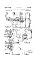
- FIGURE 1 is a plan View of a box carton blank to be folded in accordance with this invention
- FIGURE 2 is a view in perspective of the folded box
- FIGURE 3 is a view in perspective of the principal components of a box folding device comprising a feature of this invention
- FIGURE 4 is a partial plan view of the folding device and partially folded box blank
- FIGURE 5 is a front view partially cut away of the folding devices as shown in FIGURE 4;
- FIGURE 6 is a partial section view taken along line 66 of FIGURE 4.
- FIGURE 7 is a partial plan view showing a subsequent stage of operation
- FIGURE 8 is a partial section view taken along line 88 of FIGURE 7;
- FIGURE 9 is a partial section view taken along line 9-9 of FIGURE 7.
- the box 10 with which this invention is used comprises a main or bottom panel 12 with end walls 14 and side panels 16. Extending from the side edges of the side panels are locking tabs 18 which are slit at 20 diagonally inward from the tab outer edges to form locking tips 22.
- the corners are positively locked with the locking tab 18 overlying the end panels 14 and underlying tongues-24 formed in the end panels by generally C-shaped slits 26 with the locking tips 22 extending above the slits 26 to engage the inner surfaces of the end panel 14 and provide a firm interlock.
- the box folding and locking device comprises two principal components, a plunger 30 and a die 32.
- the die 32 comprises side and end rails 34 and 36 on which the side and end panels 14 and 1-6 are supported, being positively located by side restraining angles 38 and stop member 40 which engages the edge of the leading end panel 14 as it is delivered onto the die in the direction of the arrow F in FIGURE 3 by any suitable means (not shown).
- the plunger 30 is adapted to be moved down and through the die by conventional reciprocal drive means (not shown) and comprises a generally rectangular base 42 with trapezoidal side and end walls 44 and 46.
- the trapezoidal configuration of the side and end walls causes them to be inclined inwardly from their maximum widths at their base 42 for a purpose hereinafter to be described.
- the side walls 44 of the plunger are generally planar but the end walls 46 are relieved adjacent their outer edges to provide rearwardly divergent anvil surfaces 48.
- a small bracket 50 secured to each end wall as by means of screws 52 has outwardly extending ears 54 which diverge forwardly from the end wall 46 and are adapted to engage and bend outward the tongues 24 of an end panel 14 which is pressed against the plunger end wall 46.
- the rectangular base 42 engages the main panel 12 to force the box blank through the die 32.
- folding of the box blank is commenced by forcing the end panels 14 against and past stationary cam surfaces 56 on the end rails 36 to fold the end panels 14 toward upright position, i.e., toward the end walls 46 of the plunger.
- the side edges of the end walls are engaged by pairs of spring pressed fingers 58 pivoted at 59 which press on depending supports 36a for the die 32.
- the end panel folding fingers are firmly biased against the side edges of the end panels to press them against the relieved end anvil surfaces 48 of the plunger 30, the force being exerted by means of a spring 60 against an adjustable stop 6011.
- FIGURE 4 which illustrates the right-hand leading corner of the die 32 viewed in the direction of the arrow F in FIGURE 3
- the protruding fixed ears 54 on the plunger engage the tongues 24 in the end panels to bend them forwardly out of the plane of the end panels whereby the slits 26 are fully opened to receive the locking tabs 18.
- the leading faces 58a of the spring loaded fingers 58 are rounded and inclined rearwardly at their outer edges in order to permit the upper edge of the locking tab 18 to cam under it toward engagement behind the extended tongue 24.
- the side panels 16 engage inclined surfaces 62 on plates 64 which depend from the side rails 34 to commence upward folding of the side panels 16 as shown in FIGURE 5.
- the depending plates 64 in addition to functioning as stationary cam members, provide a pivotal mounting at 66 for side panel biasing fingers 68 which are spring loaded at 69 against an adjustable stop device 70.
- FIGURES 7 and 8 there is illustrated a subsequent stage of operation wherein the side panel forming fingers 68 are bending the corner edges 16a of the side panels inward through more than 90 actually to deform the corner of the box and to further insert the locking tip 18.
- the end panel forming fingers have at this point lost engagement with the end panels, but the end panels are still buckled outward by pressure of the inner surfaces of the side panels 16 against their end panel edges (FIGURE 7).
- the side panel forming fingers 68 are inclined at 68:: so that they can force the side panel edges beyond the plane of the plunger de wall 44.
- the side edges move out from under the forming fingers and enable the side and end panels to spring back toward planar disposition under their natural flexural strength, leaving the locking tip 22 firmly interlocked behind the end panel 14.
- the folded box passes beneath stripping fingers 71 (FIGURES 3 and 9) which are pivotally mounted at 72 from depending bars 74.
- the stripping fingers are spring biased to pass over the top edges of the carton so that when the plunger starts its return stroke the box is stripped from the plunger 30 and off the protruding fingers 54 thereon to drop onto a delivery platform (not shown).
- the plunger 30 and die 32 forces the box blank between the side and end rails 34 and 36.
- First theend panels 14 are folded upward by engagement of the stationary cam bars 56 and then are folded past and buckled upward by means of the spring loaded fingers 58 pressing the ends of the panels against the relieved anvil surfaces 48. This also causes the protruding fingers to fold the tongues 24 outward.
- the corner plows 61 fold the locking tabs 18 into upright planes intermediate the tongues and the end panel edges.
- a device for folding and locking corners of a 'box blank comprising a main panel, adjacent wall panels hingedly connected to said main panel, a slit in a first one of said wall panels with portions thereof disposed at an angle to each other forming a tongue directed toward the side edge of said first wall panel, a lock flap hingedly connected to the second of said wall panels along a side edge thereof, a bendable locking tip on said lock flap, said lock fiap underlying said tongue while overlying said first panel and said locking tip underlying said first panel when said corners are locked, said folding and locking device comprising:
- a plunger having a generally rectangular base and generally upright walls forming external corners
- one of said upright walls being relieved at an end thereof to form a depressed anvil surface diverging rearwardly from portions thereof displaced from said one end,
- a die including first and second rails forming internal corners through which said external corners are movable
- gauge means on said die for positioning a box blank thereon with said first and second wall panels located respectively on said first and second rails,
- first biasing means on said die engageable by the first panel of a box blank during the initial portion of the plunger travel through said internal corners to fold said first panel toward said one end wall
- third biasing means engageable by the lock flap of said box blank to fold said lock flap into a plane intermediate said side edge and the free end of said tongue
- fourth biasing means engageable by the side edge of the second panel of said box blank during a subsequent portion of the plunger travel to fold said second panel into upright position with the locking tip underlying said first panel.
- said first biasing means releases said first panel side edge during a next subsequent portion of the movement of said plunger while said fourth biasing means continues to engage said second panel.
- the box folding device defined by claim 1 including:
- spring pressed stripper means movable behind the upper edge of one of said panels at the end of the plunger travel to prevent return movement thereof with said plunger.
- resilient means biasing said finger toward said anvil surface.
- the box folding device defined by claim 4 including:
- the panel-engaging surface of said second finger being inclined rearwardly from its point of engagement with the side of a second panel
- said second finger being conditioned to swing a distance sufficient to carry said point of engagement beyond said second upright wall.
- a method of folding and locking corners of a box blank comprising a main panel, adjacent wall panels hingedly connected to said main panel, a slit in a first one of said wall panels with portions thereof disposed at an angle to each other forming a tongue directed toward the side edge of said first wall panel, a lock flap hingedly connected to the second of said wall panels along a side edge thereof, a bendable locking tip on said lock flap, said lock flap underlying said tongue while overlying said second panel and said locking tip underlying said second panel when said corners are locked, said folding and locking method comprising the steps of:
Landscapes
- Engineering & Computer Science (AREA)
- Mechanical Engineering (AREA)
- Making Paper Articles (AREA)
Description
Sept. 10, 1968 A. a. RANDLES i 3,400,640
METHOD AND APPARATUSFOR FOLDING AND LOCKING A BOX BLANK Filed July 13, 1966 4 sheets sheet 1 & 0m 20 l I Jli g L 10- L l a II I l I I a a-. l8 l8 26 'l v 5 L! i INVENTOR.
2 ARTHUR E. RANDLES ,JR.
ATTORNEYS Sept. 10, 1968 A. E. RANDLES METHOD AND APPARATUS FOR FOLDING AND LOCKING A BOX BLANK 4 Sheets-Sheet 2 Filed July 13, 1966 INVENTOR. ARTHUR E. RANDLES,JR.
ge y
ATTOR NEYS Sept. 10, 1968 A. E. RANDLES 3,400,640
METHOD AND APPARATUS FOR FOLDING AND LOCKING A BOX BLANK Filed July 13, 1966 4 Sheets-Sheet 5 I INVENTOR. "5 5 ARTHUR s. RANDLES JR.
ATTORNEYS Sept. 10, 1968 A. E. RANDLES ETHOD AND APPARATUS FOR FOLDING AND LOCKING A BOX BLANK 4 Sheets-Sheet 4- Filed July 13, 1966 INVENTOR. ARTHUR E RANQLES,JR.
ATTORNEYS 3,400,640 METHOD AND APPARATUS FOR FOLDING AND LOCKING A BOX BLANK Arthur E. Randles, 707 Warrington, Redwood City, Calif. 94063 Filed July 13, 1966, Ser. No. 569,003 8 Claims. (Cl. 93-51) ABSTRACT OF THE DISCLOSURE A device and method for folding and locking the corners of a box blank of paperboard or the like without glue or separate fastening means by interlocking male and female members integrally formed in the box panels.
One type of paperboard box in wide use today comprises a main or bottom panel and end and side panels with interlocking members. The interlocking members comprise a locking tab extending from the side edge of one wall panel which is slit diagonally inward from the outer edge to form an upstanding locking tip which enters into a slit formed in the adjacent edge of the other wall panel. The slit formed in the other wall panel is of generally C-shaped configuration forming a tongue which is disposed towards the locking tab. Thus, when engaged, the locking tab enters into the slit to underlie the tongue and overlie the adjacent wall panel but with the locking tip underlying the wall panel.
Such corner structure provides a positive lock that has proved very effective. Heretofore, however, assembly of the corner required that the locking tab be inserted under the tongue and that a separate machine element be applied to pull the tip of the locking tab through to the inside of the complementary wall panel. This requires a rather complex folding device that is rather expensive to build and less than completely reliable in operation.
It is, therefore, an object of this invention to provide a simple but reliable machine for folding and locking the corners of a box blank of the type described.
It is a further object of this invention to provide a machine for folding and locking a box blank of the type described employing a minimum number of movable parts.
It is a still further object of this invention to provide a device for folding and locking box corners of the type described by application of simple mechanisms.
In carrying out this invention, I provide a die with a generally rectangular opening comprising side and end rails with positioning means for locating a box blank with side and end panels thereof supported on the side and end rails. In cooperative association with the die is a plunger having a generally rectangular base with side and end walls of trapezoidal configuration inclining inward from maximum width from the base. The end walls of the plunger are relieved at their ends to form rearwardly inclined anvil surfaces, and protrusions adjacent the anvil surfaces are inclined forwardly. The plunger moves between the blank supporting rails to engage the main panel and force the carton through the die. During the first portion of the movement of the plunger through the die, a stationary cam surface thereon biases the box blank end panels upward toward the end walls of the plunger while plow-like members at each corner engage the locking tabs to fold them into upright position. Then, during a subsequent portion of the plunger travel, two pairs of spring pressed fingers engage the side edges of the end panels to press them firmly against the depressed anvil surfaces, bending them rearwardly while the protrusions on the plunger end walls engage the tongues to bend them forwardly out of the plane of the end panels. This opens the United States Patent Office 3,400,640- Patented Sept. 10, 1968 slit to a maximum degree to provide free entry for the interlocking tab. In addition, the rearward bending of the end wall side edges, in effect, shortens the distance to the edges so that the side walls can swing beyond without engaging them and the locking tabs can swing through a greater are below the upper edge of the C-slit to enter it across the outwardly buckled end panel.
As the plunger continues downward, the plow-like members fold the locking tabs inward to a plane intermediate that of the free end of the tongue and the rearwardly bent side edges of the end panels so that, upon further travel of the plunger, a second pair of spring pressed fingers folds the side panels upward at their edges to force the locking tabs into the slits, this movement being permitted by rearwardly inclined cam surfaces on the edges of the first pairs of spring loaded fingers which permit the locking tabs to pass under them.
During subsequent travel of the plunger the end walls pass out from under the first pair of spring pressed fingers, releasing the end panels while the second pair of fingers continue to press against the side edges of the side panels. By pressing against the edges, the side panels are buckled outward so that the locking tabs will penetrate even further into the C-slit. Then, when the box passes out from under the second spring loaded fingers, the panels snap back to generally planar configuration with the locking tip engaging the inner surface of the side panel. During the final stage of plunger travel, spring pressed stripper fingers pass over the upper edges of the side and end panels to prevent return of the folded box with the plunger.
Other objects and advantages of this invention will become apparent from the description following when read in conjunction with the accompanying drawings wherein:
FIGURE 1 is a plan View of a box carton blank to be folded in accordance with this invention;
FIGURE 2 is a view in perspective of the folded box;
FIGURE 3 is a view in perspective of the principal components of a box folding device comprising a feature of this invention;
FIGURE 4 is a partial plan view of the folding device and partially folded box blank;
FIGURE 5 is a front view partially cut away of the folding devices as shown in FIGURE 4;
FIGURE 6 is a partial section view taken along line 66 of FIGURE 4;
FIGURE 7 is a partial plan view showing a subsequent stage of operation;
FIGURE 8 is a partial section view taken along line 88 of FIGURE 7; and
FIGURE 9 is a partial section view taken along line 9-9 of FIGURE 7.
Referring more particularly to FIGURES 1 and 2, the box 10 with which this invention is used comprises a main or bottom panel 12 with end walls 14 and side panels 16. Extending from the side edges of the side panels are locking tabs 18 which are slit at 20 diagonally inward from the tab outer edges to form locking tips 22. When the box is assembled as shown in FIGURE 2, the corners are positively locked with the locking tab 18 overlying the end panels 14 and underlying tongues-24 formed in the end panels by generally C-shaped slits 26 with the locking tips 22 extending above the slits 26 to engage the inner surfaces of the end panel 14 and provide a firm interlock.
Referring now specifically to my invention, the box folding and locking device comprises two principal components, a plunger 30 and a die 32. The die 32 comprises side and end rails 34 and 36 on which the side and end panels 14 and 1-6 are supported, being positively located by side restraining angles 38 and stop member 40 which engages the edge of the leading end panel 14 as it is delivered onto the die in the direction of the arrow F in FIGURE 3 by any suitable means (not shown).
The plunger 30 is adapted to be moved down and through the die by conventional reciprocal drive means (not shown) and comprises a generally rectangular base 42 with trapezoidal side and end walls 44 and 46. The trapezoidal configuration of the side and end walls causes them to be inclined inwardly from their maximum widths at their base 42 for a purpose hereinafter to be described.
The side walls 44 of the plunger are generally planar but the end walls 46 are relieved adjacent their outer edges to provide rearwardly divergent anvil surfaces 48. A small bracket 50 secured to each end wall as by means of screws 52 has outwardly extending ears 54 which diverge forwardly from the end wall 46 and are adapted to engage and bend outward the tongues 24 of an end panel 14 which is pressed against the plunger end wall 46.
As the plunger moves downward in the direction of the arrow P, the rectangular base 42 engages the main panel 12 to force the box blank through the die 32. During additional movement of the plunger 30 through the die 32, folding of the box blank is commenced by forcing the end panels 14 against and past stationary cam surfaces 56 on the end rails 36 to fold the end panels 14 toward upright position, i.e., toward the end walls 46 of the plunger. In the next stage of the plunger travel, the side edges of the end walls are engaged by pairs of spring pressed fingers 58 pivoted at 59 which press on depending supports 36a for the die 32. The end panel folding fingers are firmly biased against the side edges of the end panels to press them against the relieved end anvil surfaces 48 of the plunger 30, the force being exerted by means of a spring 60 against an adjustable stop 6011. As the side edges are bent rearwardly to the position shown in FIGURE 4 which illustrates the right-hand leading corner of the die 32 viewed in the direction of the arrow F in FIGURE 3, the protruding fixed ears 54 on the plunger engage the tongues 24 in the end panels to bend them forwardly out of the plane of the end panels whereby the slits 26 are fully opened to receive the locking tabs 18. As shown in FIGURE 6, the leading faces 58a of the spring loaded fingers 58 are rounded and inclined rearwardly at their outer edges in order to permit the upper edge of the locking tab 18 to cam under it toward engagement behind the extended tongue 24.
As the end panels are folded, downward movement of the plunger 30 forces the locking tabs 18 against plowlike fingers 61 which extend diagonally inward and downward from the corners of the dies so that as the locking tabs move d wnward along their surfaces they are pushed inward to a plane intermediate that of the end panel side edges 14a and the forwardly bent tongues 24 as shown in FIGURE 4.
After folding of the locking tabs 18 has commenced, the side panels 16 engage inclined surfaces 62 on plates 64 which depend from the side rails 34 to commence upward folding of the side panels 16 as shown in FIGURE 5. The depending plates 64, in addition to functioning as stationary cam members, provide a pivotal mounting at 66 for side panel biasing fingers 68 which are spring loaded at 69 against an adjustable stop device 70.
Referring now to FIGURES 7 and 8, there is illustrated a subsequent stage of operation wherein the side panel forming fingers 68 are bending the corner edges 16a of the side panels inward through more than 90 actually to deform the corner of the box and to further insert the locking tip 18. The end panel forming fingers have at this point lost engagement with the end panels, but the end panels are still buckled outward by pressure of the inner surfaces of the side panels 16 against their end panel edges (FIGURE 7). It will be noted that the side panel forming fingers 68 are inclined at 68:: so that they can force the side panel edges beyond the plane of the plunger de wall 44.
Finally, during subsequent travel of the plunger, the side edges move out from under the forming fingers and enable the side and end panels to spring back toward planar disposition under their natural flexural strength, leaving the locking tip 22 firmly interlocked behind the end panel 14. Then, as the plunger reaches the end ofits stroke, the folded box passes beneath stripping fingers 71 (FIGURES 3 and 9) which are pivotally mounted at 72 from depending bars 74. The stripping fingers are spring biased to pass over the top edges of the carton so that when the plunger starts its return stroke the box is stripped from the plunger 30 and off the protruding fingers 54 thereon to drop onto a delivery platform (not shown).
Now reviewing the operation of the plunger 30 and die 32 to fold the box 10, the plunger forces the box blank between the side and end rails 34 and 36. First theend panels 14 are folded upward by engagement of the stationary cam bars 56 and then are folded past and buckled upward by means of the spring loaded fingers 58 pressing the ends of the panels against the relieved anvil surfaces 48. This also causes the protruding fingers to fold the tongues 24 outward. In the meantime, the corner plows 61 fold the locking tabs 18 into upright planes intermediate the tongues and the end panel edges.
Then the side panels are folded upward, first by the inclined cam surfaces 62 and then by engagement with the side spring loaded fingers 68 which force the side corners past 90 against the rearwardly inclined side wall of the plunger to insert the locking tabs 18 fully. Thereafter, the panels are released and they spring back to planar configuration with the corners interlocked.
While this invention has been described in conjunction with a preferred embodiment thereof, it is to be understood that modifications and changes therein may be made by those skilled in the art without departing from the spirit and scope of this invention as defined by the claims appended hereto.
Having described my invention, I claim:
1. A device for folding and locking corners of a 'box blank comprising a main panel, adjacent wall panels hingedly connected to said main panel, a slit in a first one of said wall panels with portions thereof disposed at an angle to each other forming a tongue directed toward the side edge of said first wall panel, a lock flap hingedly connected to the second of said wall panels along a side edge thereof, a bendable locking tip on said lock flap, said lock fiap underlying said tongue while overlying said first panel and said locking tip underlying said first panel when said corners are locked, said folding and locking device comprising:
a plunger having a generally rectangular base and generally upright walls forming external corners,
one of said upright walls being relieved at an end thereof to form a depressed anvil surface diverging rearwardly from portions thereof displaced from said one end,
a protrusion on said one upright wall diverging forwardly therefrom and engageable with the tongue on a first panel when the side edge thereof is biased against said anvil surface to bend said tongue away from said one upright wall,
a die including first and second rails forming internal corners through which said external corners are movable,
gauge means on said die for positioning a box blank thereon with said first and second wall panels located respectively on said first and second rails,
first biasing means on said die engageable by the first panel of a box blank during the initial portion of the plunger travel through said internal corners to fold said first panel toward said one end wall,
second biasing means on said die engageable by said first panel adjacent the side edge thereof during a secondary portion of the plunger travel to urge said first panel side edge rearward against said anvil surface with said tongue bent forward,
third biasing means engageable by the lock flap of said box blank to fold said lock flap into a plane intermediate said side edge and the free end of said tongue, and
fourth biasing means engageable by the side edge of the second panel of said box blank during a subsequent portion of the plunger travel to fold said second panel into upright position with the locking tip underlying said first panel.
2. The box folding device defined by claim 1 wherein:
said first biasing means releases said first panel side edge during a next subsequent portion of the movement of said plunger while said fourth biasing means continues to engage said second panel.
3. The box folding device defined by claim 1 including:
spring pressed stripper means movable behind the upper edge of one of said panels at the end of the plunger travel to prevent return movement thereof with said plunger.
4. The box folding device defined by claim 1 wherein said second biasing means comprises:
a finger pivotally mounted on said die to pivot in a plane transverse to said anvil surface, and
resilient means biasing said finger toward said anvil surface.
5. The box folding device defined by claim 4 including:
a cam surface on said finger inclined from a second panel biasing surface rearward toward said second rail so that said lock tab may pass under said finger during operation of said fourth biasing means.
6. The box folding device defined by claim 4 wherein:
the side and end walls of said plunger are inclined inward from said base so that panels biased against them are folded in excess of 90.
7. The box folding device defined by claim 1 wherein said fourth biasing means comprises:
a second finger pivotally mounted on said die to swing in a plane transverse to said second upright wall, and
resilient means biasing said second finger toward said second upright wall,
the panel-engaging surface of said second finger being inclined rearwardly from its point of engagement with the side of a second panel,
said second finger being conditioned to swing a distance sufficient to carry said point of engagement beyond said second upright wall.
8. A method of folding and locking corners of a box blank comprising a main panel, adjacent wall panels hingedly connected to said main panel, a slit in a first one of said wall panels with portions thereof disposed at an angle to each other forming a tongue directed toward the side edge of said first wall panel, a lock flap hingedly connected to the second of said wall panels along a side edge thereof, a bendable locking tip on said lock flap, said lock flap underlying said tongue while overlying said second panel and said locking tip underlying said second panel when said corners are locked, said folding and locking method comprising the steps of:
bending a first panel of a box blank into upright position,
bending the side edge of said first panel rearwardly and bending said tongue forwardly, to open said slit and to foreshorten said first panel,
folding the lock fiap of said carton into a plane wherein the locking tip is intermediate said side edge and the free end of said tongue, folding the second panel into upright position with the locking tip underlying the tongue on said first panel, pushing the side edge of the second panel beyond 90 so that said locking tip extends through the slit and is interior of said first panel, and releasing said first and second panels.
References Cited UNITED STATES PATENTS 2,580,180 12/1951 Meller. 2,711,677 6/1955 Stenger. 2,896,518 7/1959 Gibb 93-51 3,168,018 2/1965 Dunn 9351 3,342,114 9/1967 Dunn 93-S1 WILLIAM W. DYER, JR., Primary Examiner.
WAYNE A. MORSE, JR., Assistant Examiner.
Priority Applications (3)
| Application Number | Priority Date | Filing Date | Title |
|---|---|---|---|
| US569003A US3400640A (en) | 1966-07-13 | 1966-07-13 | Method and apparatus for folding and locking a box blank |
| NL6709571A NL6709571A (en) | 1966-07-13 | 1967-07-10 | |
| BE701305D BE701305A (en) | 1966-07-13 | 1967-07-13 |
Applications Claiming Priority (1)
| Application Number | Priority Date | Filing Date | Title |
|---|---|---|---|
| US569003A US3400640A (en) | 1966-07-13 | 1966-07-13 | Method and apparatus for folding and locking a box blank |
Publications (1)
| Publication Number | Publication Date |
|---|---|
| US3400640A true US3400640A (en) | 1968-09-10 |
Family
ID=24273691
Family Applications (1)
| Application Number | Title | Priority Date | Filing Date |
|---|---|---|---|
| US569003A Expired - Lifetime US3400640A (en) | 1966-07-13 | 1966-07-13 | Method and apparatus for folding and locking a box blank |
Country Status (3)
| Country | Link |
|---|---|
| US (1) | US3400640A (en) |
| BE (1) | BE701305A (en) |
| NL (1) | NL6709571A (en) |
Cited By (7)
| Publication number | Priority date | Publication date | Assignee | Title |
|---|---|---|---|---|
| US4283188A (en) * | 1979-04-13 | 1981-08-11 | Marq Packaging Systems, Inc. | H-section carton forming machine |
| US4464155A (en) * | 1981-12-11 | 1984-08-07 | Kliklok Corporation | Apparatus and method for forming and debowing cartons |
| EP0083812A3 (en) * | 1982-01-05 | 1984-08-22 | Kliklok Corporation | Apparatus and method for forming and debowing cartons |
| US5417641A (en) * | 1993-08-05 | 1995-05-23 | Warren; James M. | Device for folding articles |
| US5613933A (en) * | 1994-02-04 | 1997-03-25 | Advanced Container Corporation | Shipping and display box former |
| US20230226702A1 (en) * | 2022-01-19 | 2023-07-20 | Ime Automation Llc | Box folding structure for scara robot |
| US20250064661A1 (en) * | 2023-08-07 | 2025-02-27 | Vandor Group, Inc. | Method of assembling a casket from a foldable blank |
Families Citing this family (1)
| Publication number | Priority date | Publication date | Assignee | Title |
|---|---|---|---|---|
| CN113306827A (en) * | 2021-07-01 | 2021-08-27 | 全安达冷链包装科技(深圳)有限公司 | New energy environment-friendly fresh cold chain heat preservation carton and processing technology |
Citations (5)
| Publication number | Priority date | Publication date | Assignee | Title |
|---|---|---|---|---|
| US2580180A (en) * | 1947-06-23 | 1951-12-25 | Bemiss Jason Company | Method of folding cartons |
| US2711677A (en) * | 1952-04-19 | 1955-06-28 | Sutherland Paper Co | Method of erecting double walled boxes |
| US2896518A (en) * | 1956-12-27 | 1959-07-28 | Continental Can Co | Carton making machine |
| US3168018A (en) * | 1962-09-18 | 1965-02-02 | Memco Machinery Corp | Boxmaker |
| US3342114A (en) * | 1962-11-27 | 1967-09-19 | Memco Machinery Corp | Method and apparatus for making cartons from blanks |
-
1966
- 1966-07-13 US US569003A patent/US3400640A/en not_active Expired - Lifetime
-
1967
- 1967-07-10 NL NL6709571A patent/NL6709571A/xx unknown
- 1967-07-13 BE BE701305D patent/BE701305A/xx unknown
Patent Citations (5)
| Publication number | Priority date | Publication date | Assignee | Title |
|---|---|---|---|---|
| US2580180A (en) * | 1947-06-23 | 1951-12-25 | Bemiss Jason Company | Method of folding cartons |
| US2711677A (en) * | 1952-04-19 | 1955-06-28 | Sutherland Paper Co | Method of erecting double walled boxes |
| US2896518A (en) * | 1956-12-27 | 1959-07-28 | Continental Can Co | Carton making machine |
| US3168018A (en) * | 1962-09-18 | 1965-02-02 | Memco Machinery Corp | Boxmaker |
| US3342114A (en) * | 1962-11-27 | 1967-09-19 | Memco Machinery Corp | Method and apparatus for making cartons from blanks |
Cited By (9)
| Publication number | Priority date | Publication date | Assignee | Title |
|---|---|---|---|---|
| US4283188A (en) * | 1979-04-13 | 1981-08-11 | Marq Packaging Systems, Inc. | H-section carton forming machine |
| US4464155A (en) * | 1981-12-11 | 1984-08-07 | Kliklok Corporation | Apparatus and method for forming and debowing cartons |
| EP0083812A3 (en) * | 1982-01-05 | 1984-08-22 | Kliklok Corporation | Apparatus and method for forming and debowing cartons |
| US4493682A (en) * | 1982-01-05 | 1985-01-15 | Kliklok Corporation | Apparatus and method for forming and debowing cartons with pinching wheels |
| US5417641A (en) * | 1993-08-05 | 1995-05-23 | Warren; James M. | Device for folding articles |
| US5613933A (en) * | 1994-02-04 | 1997-03-25 | Advanced Container Corporation | Shipping and display box former |
| US20230226702A1 (en) * | 2022-01-19 | 2023-07-20 | Ime Automation Llc | Box folding structure for scara robot |
| US12296461B2 (en) * | 2022-01-19 | 2025-05-13 | Ime Automation Llc | Box folding structure for SCARA robot |
| US20250064661A1 (en) * | 2023-08-07 | 2025-02-27 | Vandor Group, Inc. | Method of assembling a casket from a foldable blank |
Also Published As
| Publication number | Publication date |
|---|---|
| BE701305A (en) | 1967-12-18 |
| NL6709571A (en) | 1968-01-15 |
Similar Documents
| Publication | Publication Date | Title |
|---|---|---|
| US3400640A (en) | Method and apparatus for folding and locking a box blank | |
| US2580189A (en) | Carton folder | |
| US1894209A (en) | Box-folding machine | |
| US3521536A (en) | Plunger and die mechanism for forming trays | |
| EP0083812B1 (en) | Apparatus and method for forming and debowing cartons | |
| US3521530A (en) | Plunger and die devices for interlocking box walls | |
| US3086691A (en) | Embossed locking tabs for cardboard cartons | |
| US4173173A (en) | Carton erector | |
| US2864287A (en) | Machine for folding and locking carton blanks | |
| US7360475B2 (en) | Stripping device for a press | |
| US3013711A (en) | Receptacle closure | |
| US4100843A (en) | Method and apparatus for erecting folded blanks | |
| DE202022100653U1 (en) | slip-on box | |
| US3380645A (en) | Glueless interlocks for folding box panels | |
| US3376797A (en) | Carton setting-up machine | |
| US5341983A (en) | Locking join for boxes | |
| US3400639A (en) | Forming die unit for container forming machines | |
| US766905A (en) | Paper cutting and folding machine. | |
| US3168018A (en) | Boxmaker | |
| US3053429A (en) | Corner construction for folding boxes | |
| US3412651A (en) | Method of inserting handlesinto cardboard boxes | |
| US2626545A (en) | Apparatus for setting up box blanks | |
| DK147374B (en) | FOLDEAESK, NAME FOR PASTILLES AND SIMILAR SMALL ARTICLES, AND WITH A DELIVERY OPEN COVERED BY A SLIDER FIELD | |
| US1842755A (en) | Offset locking tab for cartons | |
| US1411555A (en) | Folding paper box, box corner, and blank therefor |