US3440124A - Apparatus for manufacturing griphole carrying bags - Google Patents
Apparatus for manufacturing griphole carrying bags Download PDFInfo
- Publication number
- US3440124A US3440124A US3440124DA US3440124A US 3440124 A US3440124 A US 3440124A US 3440124D A US3440124D A US 3440124DA US 3440124 A US3440124 A US 3440124A
- Authority
- US
- United States
- Prior art keywords
- web
- griphole
- heat
- reinforcements
- reinforcing elements
- Prior art date
- Legal status (The legal status is an assumption and is not a legal conclusion. Google has not performed a legal analysis and makes no representation as to the accuracy of the status listed.)
- Expired - Lifetime
Links
- 238000004519 manufacturing process Methods 0.000 title description 37
- 239000000463 material Substances 0.000 abstract description 34
- 238000007789 sealing Methods 0.000 abstract description 31
- 238000000034 method Methods 0.000 abstract description 22
- 239000004033 plastic Substances 0.000 abstract description 22
- 229920003023 plastic Polymers 0.000 abstract description 22
- 125000006850 spacer group Chemical group 0.000 abstract description 15
- 230000002787 reinforcement Effects 0.000 abstract description 8
- 238000010438 heat treatment Methods 0.000 abstract description 4
- 238000003466 welding Methods 0.000 abstract description 2
- 230000003014 reinforcing effect Effects 0.000 description 69
- 238000005520 cutting process Methods 0.000 description 7
- 239000004020 conductor Substances 0.000 description 2
- 230000015572 biosynthetic process Effects 0.000 description 1
- 239000003795 chemical substances by application Substances 0.000 description 1
- 230000001427 coherent effect Effects 0.000 description 1
- 238000006073 displacement reaction Methods 0.000 description 1
- 238000004080 punching Methods 0.000 description 1
Images


Classifications
-
- B—PERFORMING OPERATIONS; TRANSPORTING
- B29—WORKING OF PLASTICS; WORKING OF SUBSTANCES IN A PLASTIC STATE IN GENERAL
- B29C—SHAPING OR JOINING OF PLASTICS; SHAPING OF MATERIAL IN A PLASTIC STATE, NOT OTHERWISE PROVIDED FOR; AFTER-TREATMENT OF THE SHAPED PRODUCTS, e.g. REPAIRING
- B29C66/00—General aspects of processes or apparatus for joining preformed parts
- B29C66/40—General aspects of joining substantially flat articles, e.g. plates, sheets or web-like materials; Making flat seams in tubular or hollow articles; Joining single elements to substantially flat surfaces
- B29C66/47—Joining single elements to sheets, plates or other substantially flat surfaces
-
- B—PERFORMING OPERATIONS; TRANSPORTING
- B29—WORKING OF PLASTICS; WORKING OF SUBSTANCES IN A PLASTIC STATE IN GENERAL
- B29C—SHAPING OR JOINING OF PLASTICS; SHAPING OF MATERIAL IN A PLASTIC STATE, NOT OTHERWISE PROVIDED FOR; AFTER-TREATMENT OF THE SHAPED PRODUCTS, e.g. REPAIRING
- B29C65/00—Joining or sealing of preformed parts, e.g. welding of plastics materials; Apparatus therefor
- B29C65/02—Joining or sealing of preformed parts, e.g. welding of plastics materials; Apparatus therefor by heating, with or without pressure
-
- B—PERFORMING OPERATIONS; TRANSPORTING
- B29—WORKING OF PLASTICS; WORKING OF SUBSTANCES IN A PLASTIC STATE IN GENERAL
- B29C—SHAPING OR JOINING OF PLASTICS; SHAPING OF MATERIAL IN A PLASTIC STATE, NOT OTHERWISE PROVIDED FOR; AFTER-TREATMENT OF THE SHAPED PRODUCTS, e.g. REPAIRING
- B29C66/00—General aspects of processes or apparatus for joining preformed parts
- B29C66/01—General aspects dealing with the joint area or with the area to be joined
- B29C66/05—Particular design of joint configurations
- B29C66/10—Particular design of joint configurations particular design of the joint cross-sections
- B29C66/11—Joint cross-sections comprising a single joint-segment, i.e. one of the parts to be joined comprising a single joint-segment in the joint cross-section
- B29C66/112—Single lapped joints
- B29C66/1122—Single lap to lap joints, i.e. overlap joints
-
- B—PERFORMING OPERATIONS; TRANSPORTING
- B29—WORKING OF PLASTICS; WORKING OF SUBSTANCES IN A PLASTIC STATE IN GENERAL
- B29C—SHAPING OR JOINING OF PLASTICS; SHAPING OF MATERIAL IN A PLASTIC STATE, NOT OTHERWISE PROVIDED FOR; AFTER-TREATMENT OF THE SHAPED PRODUCTS, e.g. REPAIRING
- B29C66/00—General aspects of processes or apparatus for joining preformed parts
- B29C66/50—General aspects of joining tubular articles; General aspects of joining long products, i.e. bars or profiled elements; General aspects of joining single elements to tubular articles, hollow articles or bars; General aspects of joining several hollow-preforms to form hollow or tubular articles
- B29C66/51—Joining tubular articles, profiled elements or bars; Joining single elements to tubular articles, hollow articles or bars; Joining several hollow-preforms to form hollow or tubular articles
- B29C66/53—Joining single elements to tubular articles, hollow articles or bars
- B29C66/532—Joining single elements to the wall of tubular articles, hollow articles or bars
-
- B—PERFORMING OPERATIONS; TRANSPORTING
- B29—WORKING OF PLASTICS; WORKING OF SUBSTANCES IN A PLASTIC STATE IN GENERAL
- B29C—SHAPING OR JOINING OF PLASTICS; SHAPING OF MATERIAL IN A PLASTIC STATE, NOT OTHERWISE PROVIDED FOR; AFTER-TREATMENT OF THE SHAPED PRODUCTS, e.g. REPAIRING
- B29C66/00—General aspects of processes or apparatus for joining preformed parts
- B29C66/50—General aspects of joining tubular articles; General aspects of joining long products, i.e. bars or profiled elements; General aspects of joining single elements to tubular articles, hollow articles or bars; General aspects of joining several hollow-preforms to form hollow or tubular articles
- B29C66/61—Joining from or joining on the inside
-
- B—PERFORMING OPERATIONS; TRANSPORTING
- B29—WORKING OF PLASTICS; WORKING OF SUBSTANCES IN A PLASTIC STATE IN GENERAL
- B29C—SHAPING OR JOINING OF PLASTICS; SHAPING OF MATERIAL IN A PLASTIC STATE, NOT OTHERWISE PROVIDED FOR; AFTER-TREATMENT OF THE SHAPED PRODUCTS, e.g. REPAIRING
- B29C66/00—General aspects of processes or apparatus for joining preformed parts
- B29C66/80—General aspects of machine operations or constructions and parts thereof
- B29C66/83—General aspects of machine operations or constructions and parts thereof characterised by the movement of the joining or pressing tools
- B29C66/832—Reciprocating joining or pressing tools
- B29C66/8322—Joining or pressing tools reciprocating along one axis
- B29C66/83221—Joining or pressing tools reciprocating along one axis cooperating reciprocating tools, each tool reciprocating along one axis
-
- B—PERFORMING OPERATIONS; TRANSPORTING
- B65—CONVEYING; PACKING; STORING; HANDLING THIN OR FILAMENTARY MATERIAL
- B65D—CONTAINERS FOR STORAGE OR TRANSPORT OF ARTICLES OR MATERIALS, e.g. BAGS, BARRELS, BOTTLES, BOXES, CANS, CARTONS, CRATES, DRUMS, JARS, TANKS, HOPPERS, FORWARDING CONTAINERS; ACCESSORIES, CLOSURES, OR FITTINGS THEREFOR; PACKAGING ELEMENTS; PACKAGES
- B65D33/00—Details of, or accessories for, sacks or bags
- B65D33/06—Handles
- B65D33/08—Hand holes
-
- B—PERFORMING OPERATIONS; TRANSPORTING
- B29—WORKING OF PLASTICS; WORKING OF SUBSTANCES IN A PLASTIC STATE IN GENERAL
- B29C—SHAPING OR JOINING OF PLASTICS; SHAPING OF MATERIAL IN A PLASTIC STATE, NOT OTHERWISE PROVIDED FOR; AFTER-TREATMENT OF THE SHAPED PRODUCTS, e.g. REPAIRING
- B29C65/00—Joining or sealing of preformed parts, e.g. welding of plastics materials; Apparatus therefor
- B29C65/02—Joining or sealing of preformed parts, e.g. welding of plastics materials; Apparatus therefor by heating, with or without pressure
- B29C65/18—Joining or sealing of preformed parts, e.g. welding of plastics materials; Apparatus therefor by heating, with or without pressure using heated tools
- B29C65/22—Heated wire resistive ribbon, resistive band or resistive strip
- B29C65/221—Heated wire resistive ribbon, resistive band or resistive strip characterised by the type of heated wire, resistive ribbon, band or strip
- B29C65/222—Heated wire resistive ribbon, resistive band or resistive strip characterised by the type of heated wire, resistive ribbon, band or strip comprising at least a single heated wire
-
- B—PERFORMING OPERATIONS; TRANSPORTING
- B29—WORKING OF PLASTICS; WORKING OF SUBSTANCES IN A PLASTIC STATE IN GENERAL
- B29C—SHAPING OR JOINING OF PLASTICS; SHAPING OF MATERIAL IN A PLASTIC STATE, NOT OTHERWISE PROVIDED FOR; AFTER-TREATMENT OF THE SHAPED PRODUCTS, e.g. REPAIRING
- B29C66/00—General aspects of processes or apparatus for joining preformed parts
- B29C66/40—General aspects of joining substantially flat articles, e.g. plates, sheets or web-like materials; Making flat seams in tubular or hollow articles; Joining single elements to substantially flat surfaces
- B29C66/47—Joining single elements to sheets, plates or other substantially flat surfaces
- B29C66/474—Joining single elements to sheets, plates or other substantially flat surfaces said single elements being substantially non-flat
-
- B—PERFORMING OPERATIONS; TRANSPORTING
- B29—WORKING OF PLASTICS; WORKING OF SUBSTANCES IN A PLASTIC STATE IN GENERAL
- B29C—SHAPING OR JOINING OF PLASTICS; SHAPING OF MATERIAL IN A PLASTIC STATE, NOT OTHERWISE PROVIDED FOR; AFTER-TREATMENT OF THE SHAPED PRODUCTS, e.g. REPAIRING
- B29C66/00—General aspects of processes or apparatus for joining preformed parts
- B29C66/80—General aspects of machine operations or constructions and parts thereof
- B29C66/82—Pressure application arrangements, e.g. transmission or actuating mechanisms for joining tools or clamps
- B29C66/822—Transmission mechanisms
- B29C66/8227—Transmission mechanisms using springs
-
- B—PERFORMING OPERATIONS; TRANSPORTING
- B29—WORKING OF PLASTICS; WORKING OF SUBSTANCES IN A PLASTIC STATE IN GENERAL
- B29L—INDEXING SCHEME ASSOCIATED WITH SUBCLASS B29C, RELATING TO PARTICULAR ARTICLES
- B29L2031/00—Other particular articles
- B29L2031/712—Containers; Packaging elements or accessories, Packages
- B29L2031/7128—Bags, sacks, sachets
-
- B—PERFORMING OPERATIONS; TRANSPORTING
- B31—MAKING ARTICLES OF PAPER, CARDBOARD OR MATERIAL WORKED IN A MANNER ANALOGOUS TO PAPER; WORKING PAPER, CARDBOARD OR MATERIAL WORKED IN A MANNER ANALOGOUS TO PAPER
- B31B—MAKING CONTAINERS OF PAPER, CARDBOARD OR MATERIAL WORKED IN A MANNER ANALOGOUS TO PAPER
- B31B70/00—Making flexible containers, e.g. envelopes or bags
- B31B70/74—Auxiliary operations
- B31B70/86—Forming integral handles or mounting separate handles
- B31B70/864—Mounting separate handles on bags, sheets or webs
-
- Y—GENERAL TAGGING OF NEW TECHNOLOGICAL DEVELOPMENTS; GENERAL TAGGING OF CROSS-SECTIONAL TECHNOLOGIES SPANNING OVER SEVERAL SECTIONS OF THE IPC; TECHNICAL SUBJECTS COVERED BY FORMER USPC CROSS-REFERENCE ART COLLECTIONS [XRACs] AND DIGESTS
- Y10—TECHNICAL SUBJECTS COVERED BY FORMER USPC
- Y10T—TECHNICAL SUBJECTS COVERED BY FORMER US CLASSIFICATION
- Y10T156/00—Adhesive bonding and miscellaneous chemical manufacture
- Y10T156/12—Surface bonding means and/or assembly means with cutting, punching, piercing, severing or tearing
- Y10T156/1304—Means making hole or aperture in part to be laminated
Definitions
- This invention relates to a process of manufacturing griphole carrying bags from heat-scalable material, which bags comprise walls that are provided adjacent to the gripholes with reinforcing elements made from heatsealable material, in which process, a web is intermittently advanced and gripholes are formed in the superimposed layers of the web during the standstill periods.
- Griphole carrying bags have been known for a long time. Simple strips or sectional pieces have been used as reinforcing elements.
- the previous practice in the manufacture of such carrying bags comprises initially making the bag from a section of a web of heat-scalable material. Subsequently, either the reinforcing elements are heatsealed first, which is followed by punching the gripholes, or, where sectional pieces are used as reinforcing elements, the gripholes are punched first and the sectional pieces are heat-sealed thereafter. Both manufacturing processes are complicated and time-consuming. Owing to the complication of the known processes, the manufacture of such carrying bags has not been fully mechanized so far because a suitable apparatus would be disproportionately expensive and yet could have only a small output. For this reason, manually operated devices, which are independent of each other, are used for carrying out the various steps of the known processes of making griphole carrying bags from heat-scalable material.
- This object is accomplished according to the invention in a process of the type described initially hereinbefore in that the two plies of the web formed with the gripholes are kept spaced apart at least adjacent to the gripholes during the further advance of the plies, a reinforcing element is fed to the rim of the griphole in each ply, the reinforcing elements are simultaneously heatsealed to the rims of the respective gripholes in both "ice plies, thereafter at least one heat-sealed seam extending transversely to the longitudinal direction of the web is formed, and a section of the web corresponding to the finished bag is cut off also in a direction transverse to the longitudinal direction of the web.
- the reinforcing elements are in the form of coherent strips, which are intermittently fed to the rims of the gripholes in the respective plies of the web, and one reinforcing element for each ply of the web is served during each interval between two feeding steps.
- the reinforcing elements for the rims of the gripholes may be fed to the outside or inside surfaces of the two plies of the web.
- the manufacture of griphole carrying bags having external reinforcing elements is preferable in carrying out the process according to the invention.
- the reinforcing elements for the rims of the gripholes are fed transversely to the direction of movement of a web which is substantially double-folded.
- This development of the invention may be modified in that the reinforcing elements for the rims of the gripholes are fed to the inside surfaces of the two plies in the direction of movement of a substantially double-folded web, when the free edge preferably of the upper ply of the web has been relaxed by a deflection of the web into a second plane of conveyance, which is parallel to and preferably below the previous plane of conveyance, and this relaxed edge has been spaced from the other ply adjacent to the rims of the gripholes by a deflection out of the plane of conveyance.
- the invention relates further to a strip of plastic material, preferably for use in a process of manufacturing griphole carrying bags from heat-scalable material, such as has been described hereinbefore.
- This strip is characterized according to the invention by consisting of a plurality of preformed elements, such as reinforcing elements, which are interconnected by at least one thin connecting web between adjacent elements so as to form a feeding strip, which is adapted to carry load.
- the use of the plastics material strip according to the invention is by no means restricted to the process according to the invention for the manufacture of griphole carrying bags.
- Plastics materials strips according to the invention and consisting of chains of elements may be used wherever individual elements such as handles, spouts, push-buttons or the like must be fed and must be further processed :as individual elements.
- each element of the plastics material strip has suitably the form of a closed ring so that the element ensures the provision of a reinforcement around the entire rim of the griphole.
- the invention is directed to apparatus for carrying out the process which has been described hereinbefore.
- This apparatus is characterized according to the invention in that an intermittently operating pair of withdrawing rolls for the web are provided at the end where the finished griphole carrying bag is discharged, and a burning or cutting device for forming the gripholes is arranged at the other end, the burning or cutting device is succeeded by a feeder for feeding the reinforcing elements for the rims of the gripholes and a spacer is provided adjacent to the conveyor and serves for spacing the two plies of the web apart, said spacer carries in its rear portion a heat-sealing plate, which conforms to the reinforcing elements, pressure jaws, which are movable toward and away from the heat-sealing plate, are disposed on opposite sides of the latter, each of said pressure jaws is provided with an element for transferring heat or heating current through the gripholes to the heat-sealing plate, and the pair of withdrawing rolls are succeeded by a transverse heat-sealing device and a
- the apparatus which has been described is further developed according to the invention in that the burning or cutting device is succeeded by a deflecting device, which deflects the web into a plane of conveyance which is spaced from the previous plane of conveyance, said deflecting device lifts at least the edge of one ply adjacent to the gripholes from the other ply, and heat-sealing jaws, which are movable toward and from the two plies are provided on both sides of the free edges of said plies adjacent to the deflecting device.
- the knives for severing the reinforcing elements from the plastics material strips are suitably connected to the pressure jaws.
- the knife is, according to the invention, double-edged and secured to a backing plate, which is disposed between the heat-sealing jaws and the planes in which the two layers of plies of the web are moved.
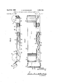
- FIGS. 1 to 4 are elevations showing four different griphole carrying bags
- FIG. 5 is a central longitudinal sectional view showing diagrammatically an apparatus for manufacturing griphole carrying bags having external reinforcing elements
- FIG. 6 is a top plan view of FIG. 5, the apparatus parts above the web being omitted,
- FIG. 7 is a sectional view taken on line VII-VII of FIG. 6 and FIG. 8 is a top plan view showing a portion of a plastics material strip which provides reinforcing elements.
- FIG. 9 is a transverse sectional view showing an apparatus for manufacturing griphole carrying bags having internal reinforcing elements, the section being taken adjacent to the heat-sealing jaws.
- FIG. 10 is a side elevation showing a portion of the web adjacent to a deflecting device for spacing the free edges of the two plies.
- FIG. 11 is a top plane view showing the web portion of FIG. 10.
- FIGS. 1 to 4 show four different griphole carrying bags 1, 2, 3, 4 having external reinforcing elements 5 and 6, which reinforce the rims of the gripholes 7 or 8 and constitute an improved grip for carrying the griphole carrying bags.
- the griphole carrying bags and the reinforcing elements consist of heat-scalable material.
- the thickness of the reinforcing elements is a multiple of the thickness of the material of the carrying bags.
- the griphole carrying bag 1 shown in FIG. 1 has a bottom seam 9 and two side gussets 10, 11. This carrying bag is made from gusseted tubing.
- the griphole carrying bag 2 shown in FIG. 2 has a bottom seam 9, like the griphole carrying bag 1, but no gussets.
- This carrying bag is made from plain tubing.
- the griphole carrying bag 3 shown in FIG. 3 has two longitudinal side seams 12, 13.
- This carrying bag is made from plain tubing, which has been longitudinally slit on one side, or from a double-folded web.
- the griphole carrying bag 4 (FIG. 4) corresponds substantially to the griphole carrying bag 3. It has two longitudinal side seams 12, 13, like the griphole carrying bag 3, and in addition a bottom gusset 14;.
- the web is intermittently advanced in its longitudinal direction, indicated by the arrow 15.
- the web is intermittently advanced in the direction of the arrow 16.
- gripholes 7 and 8 are formed in the two superimposed plies of the web during the standstill of the web. During the further conveyance of the web, the two plies are spaced apart at least adjacent to the gripholes 7, 8. After at least one step, a reinforcing element 5 or 6 is fed to the rim of the griphole in each ply. Thereafter, the two reinforcing elements are simultaneously heat-sealed to the rims of the respective gripholes.
- a heat-sealed seam extending transversely to the longitudinal direction of the web is made in the manufacturing of carrying bags having a bottom seam, or two heat-sealed seams 12, 13 extending transversely to the longitudinal direction of the web are made in the manufacture of carrying bags having side seams, and a cut is effected also in a direction which is transverse to the longitudinal direction of the web.
- each of the reinforcing elements 5 and 6 is severed from the free end of special strips, which are intermittently advanced. This severing is effected when the web is at a standstill and the elements have reached the rims of the gripholes in the two plies of the web.
- the plastic material strips for providing the reinforcing elements 5 of the griphole carrying bags 1 and 2 are shown at 17 and 18 in FIG. 5.
- a portion of a plastic material strip for providing reinforcing elements 6 for the griphole carrying bags 3 and 4- is shown at 19 in FIG. 8.
- the reinforcing elements 5 and 6 form closed rings.
- Each plastic material strip 17, 18 or 19 consists of a plurality of elements 5 or 6, which are connected to each adjacent element by two thin connecting webs 20 (FIG. 5) in the strips 17 and 18 and by one thin connecting web 20 (FIG. 8) in the strip 19.
- the illustrated griphole carrying bags 1 to 4 have external reinforcing elements.
- the griphole carrying bags 3 and 4 having side seams may also be made with internal reinforcing elements, as will be described with reference to FIGS. 9 to 11.
- FIGS. 5 to 7 show an apparatus for the fully automatic manufacture of griphole carrying bags according to FIG. 1.
- An intermittently operating pair of withdrawing rolls 21, 22 serves for intermittently advancing the gusseted tubing 23 of plastic material in the direction of the arrow 15.
- a cutting device consisting of a profiled, stationary die 24 and a platen 25, which is movable towards and away from the die, serves for the simultaneous formation of the gripholes 7 in both layers 26 and 27 of the tubing 23.
- compressed air is blown onto the die from a central air outlet opening 28 formed in the platen 25.
- the cutting device In the direction of movement of the web, the cutting device is succeeded by a pair of guide rolls 29, 30 and these are succeeded by a spacer 31, which is surrounded by the tubing 23 so that the two plies 26, 27 are spaced apart adjacent to the spacer.
- Two intermittently operated sprocket rollers 32 are mounted above and below the spacer 31, respectively, and serve for advancing the plastic material strips 17, 18 for providing the reinforcing elements.
- the plastics material strips 17 and 18 are advanced for a distance which corresponds to one reinforcing element.
- a recess of the spacer 31 accommodates a heat-sealing plate 33, in which an electric resistance wire 34 is embedded, each end of which is connected to a contact disc 36 or 37, which is mounted flush in an insulating member 35.
- the spacer 31 is succeeded by a further pair of guide rolls 38, 39.
- FIGS. 6 and 7 indicate by way of example a suitable mounting for the spacer 31.
- the spacer is carried by two pairs of rollers 40, 41 and 42, 43.
- rollers 44, 45 bear on the rollers 40 and 41 and prevent a displacement of the spacer in the direction of movement of the gusseted tubing 23 (arrow
- the rollers 40 to 43 have flanges, which engage the gussets 10, 11 of the tubing.
- the offset portions of the rollers provide for a lateral guidance of the spacer.
- Two pressure jaws 46 and 47 are disposed opposite the two heat-sealing faces of the plate 33 and are movable toward and away from the heat-sealing plate.
- Each pressure jaw 46, 47 carries a contact pin 48, which extends through a griphole in the ply 26 or 27 of the tubing 23 and resiliently bears on the contact disc 36 or 37 in the operative position of the pressure jaw.
- the other end of each contact pin is connected to a current conductor 49 or 50.
- These conductors are included in a heating circuit.
- the heating current flows intermittently through the electric resistance wire 34.
- the sealing heat is transferred from the heat-sealing plate 33 through the web plies to the interfaces.
- Each pressure jaw carries on that side which faces the sprocket roller 32 a knife 51 for severing one reinforcing element 5 at a time from the plastic material strip 17 or 18.
- the pair of withdrawing rolls 21, 22 are succeeded by a heat-sealing device for forming the transverse heat-sealed seam which subsequently constitutes the bottom seam.
- This heat-sealing device consists of a stationary jaw 52 and a jaw 53, which is movable towards and away from this stationary jaw.
- the welding device may be of any suitable type and for this reason is not shown in more detail. Those portions of the heat-sealing tools which contact the gusseted tubing are provided with a release agent or consist of nonblocking material.
- the last process step in the manufacture of the griphole carrying bags serves to sever a finished carrying bag from the web and is carried out by a stationary knife 54 and a knife 55 which is movable toward and away from this stationary knife.
- FIGS. 5 and 6 show the arrangement in the condition immediately before the advance of the web is resumed.
- the apparatus which has just been described serves for manufacturing the griphole carrying bag 1 and the griphole carrying bag 2.
- the spacer 31 is replaced by a simpler spacer.
- the apparatus shown in FIGS. 5 to 7 may also be used for manufacturing griphole carrying bags having side seams, as shown in FIGS. 3 and 4.
- the plastic material strips 17 and 18 are replaced by the plastic material strips 19 shown in FIG. 8 and consisting of a plurality of reinforcing elements 6, which are connected to each adjacent element by one thin connecting web 20.
- the non-circular gripholes extend transversely to the direction of movement of the web, indicated by the arrow 15.
- the gripholes extend in the direction of movement of the web (arrow 16).
- an additional heat-sealing device 52, 53 is required.
- the knives 54, 55 and the two pairs of heat-sealing jaws 52, 53 may be replaced by 6 a known heat-sealing and severing device (hot-wire heatsealing device) may be used.
- griphole carrying bags having a bottom seam can be manufactured in a fully mechanized process only if they are provided with external reinforcing elements
- griphole carrying bags having side seams may be made in a fully mechanized process whether they are provided with external or internal reinforcing elements because in these bags the two superimposed plies of the web are not connected at one edge of the web.
- the reinforcing elements for the rims of the gripholes are fed to the inside surfaces of the two plies of the web when these plies are spaced apart.
- FIG. 9 shows a method of laterally feeding reinforcing elements 5 to the inside surfaces of plies 60, 61 of a double-folded web 62.
- the web is intermittently advanced at right angles to the plane of the drawing.
- plastic material strips 17 and 13 are used, which are intermittently advanced by means of sprocket rollers 32 and one reinforcing element 5 is severed at a time from each of said strips. This severing is effected by means of a double-edge knife 63 during the operation of the two heat-sealing jaws 64, which are movable toward and away from the web.
- the knife 63 is secured to a backing plate 65, which is disposed between the heat-sealing jaws 64. If the handles are to be applied in this manner to the outside surfaces of the plies so that the handles extend transversely to thedirection of movement of the web, a device as shown in FIGS. 5 and 6 may be employed in a suitable orientation.
- the reinforcing elements 5 are laterally fed transversely to the direction of movement of the web 62.
- FIGS. 10 and 11 show how the reinforcing element may be fed in the manufacture of griphole carrying bags having internal reinforcing elementswhich extend in the direction of movement of the web.
- plastic material strips 19 as shown in FIG. 8 are employed.
- the carrying bags aremade from a double-folded web 66 comprising a top ply 67 and a bottom ply 68.
- a device is provided which deflects the web from a first plane of conveyance 69 (FIG.
- Heat-sealing and pressure jaws are provided between the guide elements 74, 75 and serve for heat-sealing the reinforcing elements 6 to the inside surfaces of the plies 67 and 6:8.
- the knives for severing the elements 6 from the plastic material strips 19 are secured to the pressure jaws.
- FIGS. 10 and 11 the same are hatched in FIGS. 10 and 11 and in FIGS. 1 to 5.
- the gripholes have the reference numeral 8 like the gripholes in the carrying bags in FIGS. 3 and 4.
- the raised free edge of the ply 67 is returned to a flatposition.
- the carrying bag is then finished by transversely heat-sealing the web 66 and severing a corresponding portion of the web.
- reinforcing elements which are stacked in magazines may be fed to the process directly from the magazines.
- An apparatus for manufacturing griphole carrying bags having external reinforcements requires two magazines, each of which receives one stack of reinforcing elements.
- a pusher is associated with each magazine and serves for feeding one reinforcing element at a time from the magazine to the web.
- one magazine for receiving the reinforcing elements is sufficient if there is one pusher which feeds two reinforcing elements at the same time from the magazine between the two plies of the web.
- the reinforcing elements may be connected in pairs like a snap fastener, which may be used to close the finished carrying bag.
- Apparatus for manufacturing a carrying bag from a two-ply heat scalable material comprising a conveying means for intermittently moving said material along a fixed path, means disposed adjacent said path for removing a portion of said web to form a griphole, means disposed in said path for separating said plies, means located above said path for feeding a plurality of reinforcing elements to the rims of said gripholes, means carried by one end of said separating means for heat sealing said reinforcing elements to said rims, means located in said path for applying a transverse seal to said bag and means for severing said finished bag.
- said means for heat sealing said reinforcing elements to said rims comprises a heat sealing plate disposed between said two separated plies, a pair of pressure jaws adapted to urge said reinforcing elements on to said plies over said plate, and means to transfer heat through said jaws and said plies to said plate.
- said heat transfer means comprises an electrical resistance wire embedded in said plate, a control disc mounted in said plate and connected to said wire, a contact pin carried by one end of each of said jaws which, in the operative position of the jaws, resiliently bears on said contact disc, and a current source connected to the other end of each of said aws.
- Apparatus according to claim 1 further comprising means to deflect the web into a plane of conveyance which is spaced from the previous plane of conveyance, and guide means adapted to lift at least the edge of one ply adjacent to the gripholes from the other ply, said heatsealing jaws being provided on both sides of the free edges of said plies.
- said deflecting means comprises at least one horizontal roller adapted to deflect the web from a first plane of conveyance into a second plane of conveyance, said plane being parallel to and below the first plane of conveyance, and wherein said guide means is disposed adjacent said rollers.
- said feeding means comprises a sprocket roller for said continuous strip.
- Apparatus according to claim -1 wherein said means for removing a portion of said web comprises a stationary cutting die having a profile similar to the griphole, and a platen movable toward and away from the cutting die.
- Apparatus according to claim 9 further comprising means to force air through an air outlet opening in the platen.
- said feeding means comprises a magazine carrying the reinforcing elements for both plies of the web, and a pusher cooperating with said magazine for feeding two reinforcing elements at the same time from the magazine between the two plies of the web.
Landscapes
- Engineering & Computer Science (AREA)
- Mechanical Engineering (AREA)
- Making Paper Articles (AREA)
Abstract
1,122,054. Carrier bag. WINDMÍLLER & HÍLSCHER. 17 Aug., 1965 [24 Aug., 1964], No. 35260/65. Heading A4G. In a process of and apparatus for making griphole carrier bags from heat-sealable material, two layers 26, 27 of plastics web are moved forwardly intermittently by rollers 21, 22, and during standstill periods the holes 7 are cut by a platen 25 moving on to a fixed die 24, the pieces removed being blown away by air through platen opening 28. The two layers are then spaced apart, at least adjacent the holes, e.g. by a spacer 31 and two ribbons of joined griphole reinforcements 17, 18 are fed to the web outer surfaces where, during a standstill, opposed pressure jaws 46, 47 ensure that a heating element 34 on the spacer heat seals the reinforcements around the holes. Finally the web is heat sealed transversely to form the bag bottom by welding jaws 52, 53 and cut by knife 54, 55. The apparatus can form bags from plain or edge pleated tubing with a transverse bottom seal and cut or from a side folded or pleated web with two side seals and cuts. The oval reinforcements may be joined by one part on the long axis or by two parts on the short axis to form the ribbon. If the reinforcements are placed on the inner surfaces of the web, the ribbon may be directed laterally between the webs using an internal knife with external sealing jaws or the edges of the web may be displaced at right angles to each other by guides to enable ribbon feeds and sealing jaws at right angles to each other to secure the reinforcements. The reinforcements may also be positioned by laterally pushing them from a pile and may be provided in pairs with closure snap fasteners.
Description
April 1969 A. SCHWARZKOPF 3,440,124
APPARATUS FOR MANUFACTURING GRIPHOLE CARRYING BAGS Sheet of 4 Filed Aug. 13, 1965 /NVN7'0R Augusf SCHWARZKOPF April 1969 A. SCHWARZKOPF 3,440,124
APPARATUS FOR MANUFACTURING GRIPHOLE CARRYING BAGS Filed Aug. 15, 1965 Sheet 2 of 4 //v VENI'OR AugusfSl'HWARZ/(OPF A770 IVEVS April 1969 A. SCHWARZKOPF 3,440,124
APPARATUS FOR MANUFACTURING GRIPHOLE CARRYING BAGS Sheet '3 014 Filed Aug. 13. 1965 BY m M M/fiwp 1477'0ENEK5' April 1969 A. SCHWARZKOPF 3,440,124-
APFARATUS FOR MANUFACTURING GRIPHOLE CARRYING BAGS 0 Q m W m 2 wt United States Patent U.S. Cl. 156423 11 Claims ABSTRACT OF THE DISCLOSURE Apparatus for manufacturing a carrying bag from a two-ply heat scalable material, said apparatus comprising a conveying means for intermittently moving said material along a fixed path, means disposed adjacent said path for removing a portion of said web to form a griphole, means disposed in said path for separating said plies, means located above said path for feeding a plurality of reinforcing elements to the rims of said gripholes, means carried by one end of said separating means for heat sealing said reinforcing elements to said rims, means located in said path for applying a transverse seal to said bag and means for severing said finished bag.
This invention relates to a process of manufacturing griphole carrying bags from heat-scalable material, which bags comprise walls that are provided adjacent to the gripholes with reinforcing elements made from heatsealable material, in which process, a web is intermittently advanced and gripholes are formed in the superimposed layers of the web during the standstill periods.
Griphole carrying bags have been known for a long time. Simple strips or sectional pieces have been used as reinforcing elements. The previous practice in the manufacture of such carrying bags comprises initially making the bag from a section of a web of heat-scalable material. Subsequently, either the reinforcing elements are heatsealed first, which is followed by punching the gripholes, or, where sectional pieces are used as reinforcing elements, the gripholes are punched first and the sectional pieces are heat-sealed thereafter. Both manufacturing processes are complicated and time-consuming. Owing to the complication of the known processes, the manufacture of such carrying bags has not been fully mechanized so far because a suitable apparatus would be disproportionately expensive and yet could have only a small output. For this reason, manually operated devices, which are independent of each other, are used for carrying out the various steps of the known processes of making griphole carrying bags from heat-scalable material.
In view of this state of the art, it is an object of the invention to provide a process of manufacturing griphole carrying bags of the kind described initially hereinbefore, which process is unique in that it enables a fully automatic manufacture of the bags without manual operation. The various process steps must so match each other that the process can be carried out even on a machine which can be made in a simple manner and at low cost and which has an improved output compared to the prior art.
This object is accomplished according to the invention in a process of the type described initially hereinbefore in that the two plies of the web formed with the gripholes are kept spaced apart at least adjacent to the gripholes during the further advance of the plies, a reinforcing element is fed to the rim of the griphole in each ply, the reinforcing elements are simultaneously heatsealed to the rims of the respective gripholes in both "ice plies, thereafter at least one heat-sealed seam extending transversely to the longitudinal direction of the web is formed, and a section of the web corresponding to the finished bag is cut off also in a direction transverse to the longitudinal direction of the web.
In a preferred development of the invention, the reinforcing elements are in the form of coherent strips, which are intermittently fed to the rims of the gripholes in the respective plies of the web, and one reinforcing element for each ply of the web is served during each interval between two feeding steps.
The reinforcing elements for the rims of the gripholes may be fed to the outside or inside surfaces of the two plies of the web. In the case of tubular webs, the manufacture of griphole carrying bags having external reinforcing elements is preferable in carrying out the process according to the invention.
In a development of the invention relating to the manufacture of griphole carrying bags with preferably internal reinforcing elements, the reinforcing elements for the rims of the gripholes are fed transversely to the direction of movement of a web which is substantially double-folded. This development of the invention may be modified in that the reinforcing elements for the rims of the gripholes are fed to the inside surfaces of the two plies in the direction of movement of a substantially double-folded web, when the free edge preferably of the upper ply of the web has been relaxed by a deflection of the web into a second plane of conveyance, which is parallel to and preferably below the previous plane of conveyance, and this relaxed edge has been spaced from the other ply adjacent to the rims of the gripholes by a deflection out of the plane of conveyance.
The invention relates further to a strip of plastic material, preferably for use in a process of manufacturing griphole carrying bags from heat-scalable material, such as has been described hereinbefore. This strip is characterized according to the invention by consisting of a plurality of preformed elements, such as reinforcing elements, which are interconnected by at least one thin connecting web between adjacent elements so as to form a feeding strip, which is adapted to carry load. The use of the plastics material strip according to the invention is by no means restricted to the process according to the invention for the manufacture of griphole carrying bags. Plastics materials strips according to the invention and consisting of chains of elements may be used wherever individual elements such as handles, spouts, push-buttons or the like must be fed and must be further processed :as individual elements. Within the process according to the invention, each element of the plastics material strip has suitably the form of a closed ring so that the element ensures the provision of a reinforcement around the entire rim of the griphole.
Finally, the invention is directed to apparatus for carrying out the process which has been described hereinbefore. This apparatus is characterized according to the invention in that an intermittently operating pair of withdrawing rolls for the web are provided at the end where the finished griphole carrying bag is discharged, and a burning or cutting device for forming the gripholes is arranged at the other end, the burning or cutting device is succeeded by a feeder for feeding the reinforcing elements for the rims of the gripholes and a spacer is provided adjacent to the conveyor and serves for spacing the two plies of the web apart, said spacer carries in its rear portion a heat-sealing plate, which conforms to the reinforcing elements, pressure jaws, which are movable toward and away from the heat-sealing plate, are disposed on opposite sides of the latter, each of said pressure jaws is provided with an element for transferring heat or heating current through the gripholes to the heat-sealing plate, and the pair of withdrawing rolls are succeeded by a transverse heat-sealing device and a severing device.
For the manufacture of griphole carrying bags having internal reinforcing elements, the apparatus which has been described is further developed according to the invention in that the burning or cutting device is succeeded by a deflecting device, which deflects the web into a plane of conveyance which is spaced from the previous plane of conveyance, said deflecting device lifts at least the edge of one ply adjacent to the gripholes from the other ply, and heat-sealing jaws, which are movable toward and from the two plies are provided on both sides of the free edges of said plies adjacent to the deflecting device.
In the apparatus for manufacturing griphole carrying bags having external reinforcing elements, the knives for severing the reinforcing elements from the plastics material strips are suitably connected to the pressure jaws. In an apparatus for manufacturing griphole carrying bags having internal reinforcing elements, the knife is, according to the invention, double-edged and secured to a backing plate, which is disposed between the heat-sealing jaws and the planes in which the two layers of plies of the web are moved.
Various embodiments of the invention will be described by way of example hereinafter with reference to the drawing, in which FIGS. 1 to 4 are elevations showing four different griphole carrying bags,
FIG. 5 is a central longitudinal sectional view showing diagrammatically an apparatus for manufacturing griphole carrying bags having external reinforcing elements,
FIG. 6 is a top plan view of FIG. 5, the apparatus parts above the web being omitted,
FIG. 7 is a sectional view taken on line VII-VII of FIG. 6 and FIG. 8 is a top plan view showing a portion of a plastics material strip which provides reinforcing elements.
FIG. 9 is a transverse sectional view showing an apparatus for manufacturing griphole carrying bags having internal reinforcing elements, the section being taken adjacent to the heat-sealing jaws.
FIG. 10 is a side elevation showing a portion of the web adjacent to a deflecting device for spacing the free edges of the two plies.
FIG. 11 is a top plane view showing the web portion of FIG. 10.
FIGS. 1 to 4 show four different griphole carrying bags 1, 2, 3, 4 having external reinforcing elements 5 and 6, which reinforce the rims of the gripholes 7 or 8 and constitute an improved grip for carrying the griphole carrying bags. The griphole carrying bags and the reinforcing elements consist of heat-scalable material. The thickness of the reinforcing elements is a multiple of the thickness of the material of the carrying bags.
The griphole carrying bag 1 shown in FIG. 1 has a bottom seam 9 and two side gussets 10, 11. This carrying bag is made from gusseted tubing.
The griphole carrying bag 2 shown in FIG. 2 has a bottom seam 9, like the griphole carrying bag 1, but no gussets. This carrying bag is made from plain tubing.
The griphole carrying bag 3 shown in FIG. 3 has two longitudinal side seams 12, 13. This carrying bag is made from plain tubing, which has been longitudinally slit on one side, or from a double-folded web.
The griphole carrying bag 4 (FIG. 4) corresponds substantially to the griphole carrying bag 3. It has two longitudinal side seams 12, 13, like the griphole carrying bag 3, and in addition a bottom gusset 14;.
In the fully automatic manufacture of the griphole carrying bags 1 and 2 by the process according to the invention, the web is intermittently advanced in its longitudinal direction, indicated by the arrow 15. In the manufacture of the griphole carrying bags 3 and 4, the web is intermittently advanced in the direction of the arrow 16.
4 Thus, the heat-sealed seams 9 and 12, 13 are transverse to the web.
In the manufacture of the griphole carrying bags 1 to 4 by the process according to the invention gripholes 7 and 8 are formed in the two superimposed plies of the web during the standstill of the web. During the further conveyance of the web, the two plies are spaced apart at least adjacent to the gripholes 7, 8. After at least one step, a reinforcing element 5 or 6 is fed to the rim of the griphole in each ply. Thereafter, the two reinforcing elements are simultaneously heat-sealed to the rims of the respective gripholes. After one or more further steps, a heat-sealed seam extending transversely to the longitudinal direction of the web is made in the manufacturing of carrying bags having a bottom seam, or two heat-sealed seams 12, 13 extending transversely to the longitudinal direction of the web are made in the manufacture of carrying bags having side seams, and a cut is effected also in a direction which is transverse to the longitudinal direction of the web.
In the manufacture of the griphole carrying bags 1 to 4, each of the reinforcing elements 5 and 6 is severed from the free end of special strips, which are intermittently advanced. This severing is effected when the web is at a standstill and the elements have reached the rims of the gripholes in the two plies of the web.
The plastic material strips for providing the reinforcing elements 5 of the griphole carrying bags 1 and 2 are shown at 17 and 18 in FIG. 5. A portion of a plastic material strip for providing reinforcing elements 6 for the griphole carrying bags 3 and 4- is shown at 19 in FIG. 8. The reinforcing elements 5 and 6 form closed rings. Each plastic material strip 17, 18 or 19 consists of a plurality of elements 5 or 6, which are connected to each adjacent element by two thin connecting webs 20 (FIG. 5) in the strips 17 and 18 and by one thin connecting web 20 (FIG. 8) in the strip 19.
The illustrated griphole carrying bags 1 to 4 have external reinforcing elements. The griphole carrying bags 3 and 4 having side seams may also be made with internal reinforcing elements, as will be described with reference to FIGS. 9 to 11.
FIGS. 5 to 7 show an apparatus for the fully automatic manufacture of griphole carrying bags according to FIG. 1. An intermittently operating pair of withdrawing rolls 21, 22 serves for intermittently advancing the gusseted tubing 23 of plastic material in the direction of the arrow 15. (FIGS. 5 and 6.) A cutting device consisting of a profiled, stationary die 24 and a platen 25, which is movable towards and away from the die, serves for the simultaneous formation of the gripholes 7 in both layers 26 and 27 of the tubing 23. To ensure that the plastic material sheets punched out of the plies 26 and 27 are discharged through the die 24, compressed air is blown onto the die from a central air outlet opening 28 formed in the platen 25.
In the direction of movement of the web, the cutting device is succeeded by a pair of guide rolls 29, 30 and these are succeeded by a spacer 31, which is surrounded by the tubing 23 so that the two plies 26, 27 are spaced apart adjacent to the spacer. Two intermittently operated sprocket rollers 32 are mounted above and below the spacer 31, respectively, and serve for advancing the plastic material strips 17, 18 for providing the reinforcing elements. During the time in which the gusseted tubing 23 is advanced by the pair of withdrawing rolls 21, 22 for a distance which corresponds to the length of a carrying bag, the plastics material strips 17 and 18 are advanced for a distance which corresponds to one reinforcing element.
A recess of the spacer 31 accommodates a heat-sealing plate 33, in which an electric resistance wire 34 is embedded, each end of which is connected to a contact disc 36 or 37, which is mounted flush in an insulating member 35. In the direction of movement of the web, the spacer 31 is succeeded by a further pair of guide rolls 38, 39. FIGS. 6 and 7 indicate by way of example a suitable mounting for the spacer 31. The spacer is carried by two pairs of rollers 40, 41 and 42, 43. Two pairs of rollers 44, 45 bear on the rollers 40 and 41 and prevent a displacement of the spacer in the direction of movement of the gusseted tubing 23 (arrow The rollers 40 to 43 have flanges, which engage the gussets 10, 11 of the tubing. The offset portions of the rollers provide for a lateral guidance of the spacer.
Two pressure jaws 46 and 47 are disposed opposite the two heat-sealing faces of the plate 33 and are movable toward and away from the heat-sealing plate. Each pressure jaw 46, 47 carries a contact pin 48, which extends through a griphole in the ply 26 or 27 of the tubing 23 and resiliently bears on the contact disc 36 or 37 in the operative position of the pressure jaw. The other end of each contact pin is connected to a current conductor 49 or 50. These conductors are included in a heating circuit. The heating current flows intermittently through the electric resistance wire 34. The sealing heat is transferred from the heat-sealing plate 33 through the web plies to the interfaces. Each pressure jaw carries on that side which faces the sprocket roller 32 a knife 51 for severing one reinforcing element 5 at a time from the plastic material strip 17 or 18.
In the direction of movement of the web, the pair of withdrawing rolls 21, 22 are succeeded by a heat-sealing device for forming the transverse heat-sealed seam which subsequently constitutes the bottom seam. This heat-sealing device consists of a stationary jaw 52 and a jaw 53, which is movable towards and away from this stationary jaw. The welding device may be of any suitable type and for this reason is not shown in more detail. Those portions of the heat-sealing tools which contact the gusseted tubing are provided with a release agent or consist of nonblocking material.
The last process step in the manufacture of the griphole carrying bags serves to sever a finished carrying bag from the web and is carried out by a stationary knife 54 and a knife 55 which is movable toward and away from this stationary knife.
The movements of the platen 25, the pressure jaws 46, 47, the heat-sealing jaw 53 and the knife 55 toward the web are effected at the same time. The advance of the gus seted tubing 23 and of the plastics material strips 17 and 18 are also effected at the same time when those parts which are displaceable at right angles to the plane of the web are in their inoperative position.
As is particularly well apparent from FIG. 6, the withdrawing rolls 21, 22 and the guide rolls 38, 39 are offset adjacent to the reinforcing elements 5 by the thickness of these elements so that a satisfactory advance of the web throughout the apparatus is ensured. FIGS. 5 and 6 show the arrangement in the condition immediately before the advance of the web is resumed.
The apparatus which has just been described serves for manufacturing the griphole carrying bag 1 and the griphole carrying bag 2. In the manufacture of the griphole carrying bag 2, the spacer 31 is replaced by a simpler spacer.
Basically, the apparatus shown in FIGS. 5 to 7 may also be used for manufacturing griphole carrying bags having side seams, as shown in FIGS. 3 and 4. In this case, the plastic material strips 17 and 18 are replaced by the plastic material strips 19 shown in FIG. 8 and consisting of a plurality of reinforcing elements 6, which are connected to each adjacent element by one thin connecting web 20. In the griphole carrying bags 1 and 2 the non-circular gripholes extend transversely to the direction of movement of the web, indicated by the arrow 15. In the griphole carrying bags 3 and 4, the gripholes extend in the direction of movement of the web (arrow 16). To form the heat-sealed seam 13, which is second in the direction of movement of the web, an additional heat-sealing device 52, 53 is required. The knives 54, 55 and the two pairs of heat-sealing jaws 52, 53, may be replaced by 6 a known heat-sealing and severing device (hot-wire heatsealing device) may be used.
Whereas griphole carrying bags having a bottom seam can be manufactured in a fully mechanized process only if they are provided with external reinforcing elements, griphole carrying bags having side seams may be made in a fully mechanized process whether they are provided with external or internal reinforcing elements because in these bags the two superimposed plies of the web are not connected at one edge of the web. In the manufacture of griphole carrying bags having internal reinforcing elements, the reinforcing elements for the rims of the gripholes are fed to the inside surfaces of the two plies of the web when these plies are spaced apart.
FIG. 9 shows a method of laterally feeding reinforcing elements 5 to the inside surfaces of plies 60, 61 of a double-folded web 62. In this case the web is intermittently advanced at right angles to the plane of the drawing. As in the device that has been described with reference to FIGS. 5 to 7, plastic material strips 17 and 13 are used, which are intermittently advanced by means of sprocket rollers 32 and one reinforcing element 5 is severed at a time from each of said strips. This severing is effected by means of a double-edge knife 63 during the operation of the two heat-sealing jaws 64, which are movable toward and away from the web. The knife 63 is secured to a backing plate 65, which is disposed between the heat-sealing jaws 64. If the handles are to be applied in this manner to the outside surfaces of the plies so that the handles extend transversely to thedirection of movement of the web, a device as shown in FIGS. 5 and 6 may be employed in a suitable orientation.
In the embodiment just described, the reinforcing elements 5 are laterally fed transversely to the direction of movement of the web 62. 'FIGS. 10 and 11 show how the reinforcing element may be fed in the manufacture of griphole carrying bags having internal reinforcing elementswhich extend in the direction of movement of the web. In this embodiment, plastic material strips 19 as shown in FIG. 8 are employed. The carrying bags aremade from a double-folded web 66 comprising a top ply 67 and a bottom ply 68. To introduce the reinforcing elements 6 for the rims of the griphole between the two plies, a device is provided which deflects the web from a first plane of conveyance 69 (FIG. 10) into a second plane of conveyance 70, which is parallel to the former, and from the plane 70 back into the first plane of con- 'veyance, and which holds the relaxed free edge of the ply 67 of the web 66 out of the plane of conveyance 70. The web is deflected by rollers 71, '72, 73 and a further roller, which is not shown owing to the lack of space and corresponds to the roller 71. A guide rod 74 is provided for deflecting the free edge of the ply 67. A guide bar 75 is provided close to the roller 73 and serves for holding the free edge of the ply 67. Heat-sealing and pressure jaws, not shown, are provided between the guide elements 74, 75 and serve for heat-sealing the reinforcing elements 6 to the inside surfaces of the plies 67 and 6:8. The knives for severing the elements 6 from the plastic material strips 19 are secured to the pressure jaws. To indicate that the reinforcing elements have been heat-sealed, the same are hatched in FIGS. 10 and 11 and in FIGS. 1 to 5. In FIGS. 10 and 11, the gripholes have the reference numeral 8 like the gripholes in the carrying bags in FIGS. 3 and 4.
During the movement of the web from the plane of conveyance 70 into the plane of conveyance 69, the raised free edge of the ply 67 is returned to a flatposition. The carrying bag is then finished by transversely heat-sealing the web 66 and severing a corresponding portion of the web.
Instead of reinforcing elements combined in plastic material strips 17 to 19, reinforcing elements which are stacked in magazines may be fed to the process directly from the magazines. -An apparatus for manufacturing griphole carrying bags having external reinforcements requires two magazines, each of which receives one stack of reinforcing elements. A pusher is associated with each magazine and serves for feeding one reinforcing element at a time from the magazine to the web. In an apparatus for manufacturing carrying bags having internal reinforcing elements, one magazine for receiving the reinforcing elements is sufficient if there is one pusher which feeds two reinforcing elements at the same time from the magazine between the two plies of the web. In this case, the reinforcing elements may be connected in pairs like a snap fastener, which may be used to close the finished carrying bag.
What is claimed is:
1. Apparatus for manufacturing a carrying bag from a two-ply heat scalable material, said apparatus comprising a conveying means for intermittently moving said material along a fixed path, means disposed adjacent said path for removing a portion of said web to form a griphole, means disposed in said path for separating said plies, means located above said path for feeding a plurality of reinforcing elements to the rims of said gripholes, means carried by one end of said separating means for heat sealing said reinforcing elements to said rims, means located in said path for applying a transverse seal to said bag and means for severing said finished bag.
2. The apparatus of claim 1 wherein said means for heat sealing said reinforcing elements to said rims comprises a heat sealing plate disposed between said two separated plies, a pair of pressure jaws adapted to urge said reinforcing elements on to said plies over said plate, and means to transfer heat through said jaws and said plies to said plate.
3. Apparatus according to claim 2 wherein said reinforcing elements are fed to said rims in the form of a continuous strip and wherein said jaws are provided with a knife for severing said reinforcing elements.
4. Apparatus according to claim 3 wherein said knife is double-edged and is disposed between the heat-sealing jaws and the planes in which the two plies of the web are moved.
5. Apparatus according to claim 2 wherein said heat transfer means comprises an electrical resistance wire embedded in said plate, a control disc mounted in said plate and connected to said wire, a contact pin carried by one end of each of said jaws which, in the operative position of the jaws, resiliently bears on said contact disc, and a current source connected to the other end of each of said aws.
6. Apparatus according to claim 1 further comprising means to deflect the web into a plane of conveyance which is spaced from the previous plane of conveyance, and guide means adapted to lift at least the edge of one ply adjacent to the gripholes from the other ply, said heatsealing jaws being provided on both sides of the free edges of said plies.
7. Apparatus according to claim 6 wherein said deflecting means comprises at least one horizontal roller adapted to deflect the web from a first plane of conveyance into a second plane of conveyance, said plane being parallel to and below the first plane of conveyance, and wherein said guide means is disposed adjacent said rollers.
8. Apparatus according to claim 1 wherein said feeding means comprises a sprocket roller for said continuous strip.
9. Apparatus according to claim -1 wherein said means for removing a portion of said web comprises a stationary cutting die having a profile similar to the griphole, and a platen movable toward and away from the cutting die.
v10. Apparatus according to claim 9 further comprising means to force air through an air outlet opening in the platen.
1 1. Apparatus according to claim 1 wherein said feeding means comprises a magazine carrying the reinforcing elements for both plies of the web, and a pusher cooperating with said magazine for feeding two reinforcing elements at the same time from the magazine between the two plies of the web.
References Cited UNITED STATES PATENTS 2,372,008 3/1945 Krueger 9335 2,958,437 11/1960 Mengis 9335 3,302,860 2/ 1967 Schwarzkopf 22954 DOUGLAS I. DRUMMOND, Primary Examiner.
US. Cl. X.R.
Applications Claiming Priority (1)
| Application Number | Priority Date | Filing Date | Title |
|---|---|---|---|
| DEW0037432 | 1964-08-24 |
Publications (1)
| Publication Number | Publication Date |
|---|---|
| US3440124A true US3440124A (en) | 1969-04-22 |
Family
ID=7601474
Family Applications (1)
| Application Number | Title | Priority Date | Filing Date |
|---|---|---|---|
| US3440124D Expired - Lifetime US3440124A (en) | 1964-08-24 | 1965-08-13 | Apparatus for manufacturing griphole carrying bags |
Country Status (4)
| Country | Link |
|---|---|
| US (1) | US3440124A (en) |
| BE (1) | BE668659A (en) |
| DE (1) | DE1479848B2 (en) |
| GB (1) | GB1122054A (en) |
Cited By (14)
| Publication number | Priority date | Publication date | Assignee | Title |
|---|---|---|---|---|
| US3568576A (en) * | 1967-07-01 | 1971-03-09 | Michael Lehmacher | Method of producing carrier bags |
| US3595139A (en) * | 1969-07-18 | 1971-07-27 | Schjeldahl Co G T | Apparatus for nesting bags |
| US3687020A (en) * | 1970-06-08 | 1972-08-29 | Illinois Tool Works | Method of making container carrier structure |
| US3720141A (en) * | 1970-04-08 | 1973-03-13 | Fmc Corp | Apparatus for making thermoplastic handle bags |
| US3865018A (en) * | 1972-11-20 | 1975-02-11 | Mintz Charlotte | Apparatus for making plastic bags with handles |
| US3880700A (en) * | 1973-05-15 | 1975-04-29 | Mackenzie Trading Co Ltd | Apparatus for applying handles to plastic bags |
| US3962023A (en) * | 1974-07-17 | 1976-06-08 | Mackenzie Trading Co. Ltd. | Apparatus for applying handles to plastic bags |
| US4268338A (en) * | 1979-08-20 | 1981-05-19 | Peterson Electronic Die Co. | Method and apparatus for RF sealing of thermoplastic layers |
| US20030077006A1 (en) * | 2001-10-23 | 2003-04-24 | Siegel Kenneth D. | Flexible pouch with reinforced handle |
| US20110170804A1 (en) * | 2010-01-13 | 2011-07-14 | Marc Mamiye | Slide dispensing sealed pouch |
| US20110249915A1 (en) * | 2010-04-13 | 2011-10-13 | Tai Chi-Jung | Bag structure |
| CN110040342A (en) * | 2019-04-25 | 2019-07-23 | 何梦丹 | A kind of environmentally-friendly plastic packaging bag, processing unit (plant) and its production method |
| CN113263779A (en) * | 2021-07-05 | 2021-08-17 | 于秀滨 | A compression fittings for rice bag hand is buckled |
| CN115891286A (en) * | 2022-11-21 | 2023-04-04 | 青岛朗夫科技股份有限公司 | A liner bag heat sealing machine |
Families Citing this family (9)
| Publication number | Priority date | Publication date | Assignee | Title |
|---|---|---|---|---|
| DK131238B (en) * | 1973-08-07 | 1975-06-16 | Novoplastics Emballage As | Method for applying foil pieces to two mutually overlapping webs of material and apparatus for carrying out the method. |
| DE2527217C2 (en) * | 1975-06-19 | 1981-12-17 | Windmöller & Hölscher, 4540 Lengerich | Method and device for applying reinforcements in the handle area of bags |
| DE2528597C2 (en) * | 1975-06-26 | 1984-06-07 | Windmöller & Hölscher, 4540 Lengerich | Device for the application in pairs of reinforcement labels glued on one side to the outside of a semi-tubular film web for the production of bags |
| FR2606608A1 (en) * | 1986-11-19 | 1988-05-20 | Parrochia Maxime | Bag with reinforced hand-hole handles |
| DE3835021A1 (en) * | 1988-10-14 | 1990-04-19 | Effem Gmbh | METHOD FOR PRODUCING A TUBE BAG |
| DE3841580C1 (en) * | 1988-12-09 | 1990-07-26 | W.L. Gore & Associates Gmbh, 8011 Putzbrunn, De | Hot-air nozzle for a hot-air welding machine |
| GB2250011A (en) * | 1990-11-21 | 1992-05-27 | Decoflex Ltd | Bag with reinforced handle |
| GB2264690A (en) * | 1992-03-06 | 1993-09-08 | John Madeley | Gusseted carrier bags |
| CN112721316B (en) * | 2020-12-29 | 2022-12-20 | 成都市兴恒泰印务有限公司 | Production process for producing special-shaped packaging bags |
Citations (3)
| Publication number | Priority date | Publication date | Assignee | Title |
|---|---|---|---|---|
| US2372008A (en) * | 1942-02-11 | 1945-03-20 | Theodore H Krueger | Making of bags and envelopes |
| US2958437A (en) * | 1956-08-29 | 1960-11-01 | Wolf Brothers Inc | Method and apparatus for applying patches to a moving web |
| US3302860A (en) * | 1964-12-30 | 1967-02-07 | Windmoeller & Hoelscher | Griphole carrying bag of heat-sealable material |
-
1964
- 1964-08-24 DE DE19641479848 patent/DE1479848B2/en active Pending
-
1965
- 1965-08-13 US US3440124D patent/US3440124A/en not_active Expired - Lifetime
- 1965-08-17 GB GB3526065A patent/GB1122054A/en not_active Expired
- 1965-08-23 BE BE668659D patent/BE668659A/xx unknown
Patent Citations (3)
| Publication number | Priority date | Publication date | Assignee | Title |
|---|---|---|---|---|
| US2372008A (en) * | 1942-02-11 | 1945-03-20 | Theodore H Krueger | Making of bags and envelopes |
| US2958437A (en) * | 1956-08-29 | 1960-11-01 | Wolf Brothers Inc | Method and apparatus for applying patches to a moving web |
| US3302860A (en) * | 1964-12-30 | 1967-02-07 | Windmoeller & Hoelscher | Griphole carrying bag of heat-sealable material |
Cited By (16)
| Publication number | Priority date | Publication date | Assignee | Title |
|---|---|---|---|---|
| US3568576A (en) * | 1967-07-01 | 1971-03-09 | Michael Lehmacher | Method of producing carrier bags |
| US3595139A (en) * | 1969-07-18 | 1971-07-27 | Schjeldahl Co G T | Apparatus for nesting bags |
| US3720141A (en) * | 1970-04-08 | 1973-03-13 | Fmc Corp | Apparatus for making thermoplastic handle bags |
| US3687020A (en) * | 1970-06-08 | 1972-08-29 | Illinois Tool Works | Method of making container carrier structure |
| US3865018A (en) * | 1972-11-20 | 1975-02-11 | Mintz Charlotte | Apparatus for making plastic bags with handles |
| US3880700A (en) * | 1973-05-15 | 1975-04-29 | Mackenzie Trading Co Ltd | Apparatus for applying handles to plastic bags |
| US3962023A (en) * | 1974-07-17 | 1976-06-08 | Mackenzie Trading Co. Ltd. | Apparatus for applying handles to plastic bags |
| US4268338A (en) * | 1979-08-20 | 1981-05-19 | Peterson Electronic Die Co. | Method and apparatus for RF sealing of thermoplastic layers |
| US20030077006A1 (en) * | 2001-10-23 | 2003-04-24 | Siegel Kenneth D. | Flexible pouch with reinforced handle |
| US6923574B2 (en) | 2001-10-23 | 2005-08-02 | Kenneth D. Siegel | Flexible pouch with reinforced handle |
| US20110170804A1 (en) * | 2010-01-13 | 2011-07-14 | Marc Mamiye | Slide dispensing sealed pouch |
| US20110249915A1 (en) * | 2010-04-13 | 2011-10-13 | Tai Chi-Jung | Bag structure |
| CN110040342A (en) * | 2019-04-25 | 2019-07-23 | 何梦丹 | A kind of environmentally-friendly plastic packaging bag, processing unit (plant) and its production method |
| CN113263779A (en) * | 2021-07-05 | 2021-08-17 | 于秀滨 | A compression fittings for rice bag hand is buckled |
| CN115891286A (en) * | 2022-11-21 | 2023-04-04 | 青岛朗夫科技股份有限公司 | A liner bag heat sealing machine |
| CN115891286B (en) * | 2022-11-21 | 2025-11-04 | 青岛朗夫科技股份有限公司 | A heat sealing machine for inner lining bags |
Also Published As
| Publication number | Publication date |
|---|---|
| DE1479848A1 (en) | 1971-01-28 |
| GB1122054A (en) | 1968-07-31 |
| DE1479848B2 (en) | 1971-01-28 |
| BE668659A (en) | 1965-12-16 |
Similar Documents
| Publication | Publication Date | Title |
|---|---|---|
| US3599388A (en) | Method of and apparatus for forming and loading containers | |
| US3618286A (en) | Bag filling sealing and separating system | |
| CA1161679A (en) | Method and apparatus for producing plastics bags | |
| US4452597A (en) | Method and apparatus for forming stacks of sacks | |
| US4268346A (en) | Apparatus for making tank top bags from a web of tubular plastics film provided with side folds | |
| US4181069A (en) | Method for producing double streams of side-welded bags in heat-welded pad form | |
| EP0276554A2 (en) | Bag with resealable closure and a method of manufacturing same | |
| US4883450A (en) | Process for making single side free plastic bag | |
| US4278198A (en) | Flexible collapsible container with a stiffening member | |
| US20030054931A1 (en) | Methods of manufacturing reclosable packages; and packages made thereby | |
| US2620205A (en) | Sheet material articles in sequence | |
| JP4890757B2 (en) | Forming, loading and sealing machine | |
| US3053723A (en) | Article fabricating apparatus and method | |
| US6117060A (en) | Continuous supply of preformed reclosable fasteners | |
| GB1122054A (en) | Manufacture of grip-hole carrier bags | |
| US6656101B2 (en) | Container liners | |
| DE3377477D1 (en) | Method and device for manufacturing and stocking thermoplastic bags | |
| EP1459986A1 (en) | Method and apparatus for zipper strip attachment | |
| EP1477080A1 (en) | Method and apparatus for inserting sliders during automated manufacture of reclosable bags | |
| US3810420A (en) | Machines for the manufacture of plastic bags | |
| EP1681238A1 (en) | Method and apparatus for making reclosable packages having slider actuated string zippers | |
| US4065344A (en) | Bag forming method and apparatus | |
| US4175994A (en) | Method of manufacturing a flexible collapsible container with a stiffening member | |
| JP2002283476A (en) | Method and apparatus for producing bag with complementary-fitting sealing band and bag obtained thereby | |
| US4584706A (en) | Chain of laterally interconnected bags |