US3441966A - Heel finishing machines - Google Patents
Heel finishing machines Download PDFInfo
- Publication number
- US3441966A US3441966A US462657A US3441966DA US3441966A US 3441966 A US3441966 A US 3441966A US 462657 A US462657 A US 462657A US 3441966D A US3441966D A US 3441966DA US 3441966 A US3441966 A US 3441966A
- Authority
- US
- United States
- Prior art keywords
- shoe
- heel
- arm
- jack
- tool
- Prior art date
- Legal status (The legal status is an assumption and is not a legal conclusion. Google has not performed a legal analysis and makes no representation as to the accuracy of the status listed.)
- Expired - Lifetime
Links
- 238000009991 scouring Methods 0.000 description 44
- 230000033001 locomotion Effects 0.000 description 36
- 230000007246 mechanism Effects 0.000 description 16
- 210000000481 breast Anatomy 0.000 description 15
- 238000013459 approach Methods 0.000 description 5
- 238000009877 rendering Methods 0.000 description 5
- 238000010276 construction Methods 0.000 description 3
- 238000010586 diagram Methods 0.000 description 3
- 230000002093 peripheral effect Effects 0.000 description 3
- 238000009966 trimming Methods 0.000 description 3
- 230000000994 depressogenic effect Effects 0.000 description 2
- 230000000694 effects Effects 0.000 description 2
- 230000001788 irregular Effects 0.000 description 2
- 229940002865 4-way Drugs 0.000 description 1
- 239000003082 abrasive agent Substances 0.000 description 1
- 239000011230 binding agent Substances 0.000 description 1
- 230000006835 compression Effects 0.000 description 1
- 238000007906 compression Methods 0.000 description 1
- 239000000428 dust Substances 0.000 description 1
- 229910001651 emery Inorganic materials 0.000 description 1
- 239000004744 fabric Substances 0.000 description 1
- 239000002184 metal Substances 0.000 description 1
- 238000000034 method Methods 0.000 description 1
- 239000000203 mixture Substances 0.000 description 1
- 239000013641 positive control Substances 0.000 description 1
- 230000002028 premature Effects 0.000 description 1
- 230000011664 signaling Effects 0.000 description 1
- 239000007787 solid Substances 0.000 description 1
Images


Classifications
-
- A—HUMAN NECESSITIES
- A43—FOOTWEAR
- A43D—MACHINES, TOOLS, EQUIPMENT OR METHODS FOR MANUFACTURING OR REPAIRING FOOTWEAR
- A43D25/00—Devices for gluing shoe parts
- A43D25/06—Devices for gluing soles on shoe bottoms
Definitions
- the tool is yieldingly engageable with the heel as the heel is rotated to present its entire periphery to the tool.
- Automatic means are provided for urging the tool into and out of engagement with the shoe whereby contact is first made in the shank area against the edge of the sole slightly toewardly of the breast line. Further automatic means are provided to assure that the shoe is rotating when initial contact is made and that the tool is removed from engagement with the shoe before rotation stops.
- control lever cylinder 186 an air cylinder also known as the control lever cylinder 186.
- the cylinder 186 is supported by the arm 181 and hence is rotatable as a unit about the stud 180, it is also pivotal with respect to the arm 181 about the axis of the pin184.
- the motor M is turned on and the handles of both of the manual start values V1 and V2 are depressed, it being required that both valves be actuated to start the machine for obvious reasons of operator safety.
- a 4-way valve A (FIG. 13) is shifted causing pressurized air to be supplied to the limit valve 6B which is located in the clamp arm 16 (FIG. 3).
- This valve is normally held in the position shown in FIGS. 3 and 13 by its spring whereupon its plunger 37 holds the small bell crank 39 in its lowered position within the slot 41 ready to be actuated by subsequent upward locking movement of the clamp post 15. Air is also exhausted from the piston rod end of the jack post cylinder 22 (FIG. 4) through the valve 10A.
- the stop arm cylinder 268 on the jack operating slide 44 (FIGS. 8 and 10) is pressurized with its rod 266 pivoting the latch 250 in a counterclockwise direction as seen in FIG. 8 which unlatches the slide 44 permitting it to be moved by the jack rotation cylinder 45 to the right or toward the FIG. 8 position when the cylinder 45 becomes pressurized.
- the limit valve 6C (FIG. 8) is also released causing 3-way valve 14A (FIG. 13) to shift to the spring held position. This in turn causes the jack rotation cylinder 45 to become pressurized and begin movement of the slide 44 to the right, as viewed in FIG. 8 or left as viewed in FIG.
- the feeler 122 extending from beneath the periphery of the scouring wheel 60 first engages the shoe in the crease between the outsole and upper as seen in FIGS. 3 and 5, and since the scouring wheel 60 and the feeler are then free to rise, the feeler 122 moves inwardly and upwardly into position followed closely by the scouring wheel 60 engaging the then rotating shoe.
- the feeler and wheel maintain a floating relationship to the shoe throughout the trimming cycle following variations in height about the heel periphery.
- cam follower 174 (FIGS. 8 to 10) is in engagement with the wing or lobe 286 on the cam C at the beginning of the clockwise rotation of the cam and shoe. This prevents premature engagement of the scouring wheel with the heel or sole edge and etfectively retards engagement until after the shoe has begun to rotate. As the follower 174 leaves the lobe 286 and engages the periphery of the heel shaped portion of the cam C the then rotating scouring wheel 60 engages the shoe toewardly of the breast line making initial contact approximately /2" ahead of the breast line at the edge of the sole.
- the scouring cut which in effect removes very little stock, begins when the various mechanisms are in the positions shown in FIG. 9.
- the scouring operation is half completed when the cam C has been rotated to the FIG. 10 position.
- the wheel 60 is held in engagement with the heel by the force of the spring 160.
- a gap exists between the roller 198 on the 'bell crank 194 and the plate 156 located on the arm 154 whereby the scouring arm and hence the wheel are not under the control of the cam C.
- the heel having been previously trimmed with an accurate periphery is its own guide for the scouring wheel, the feeler only guiding the wheel in an up and down direction with respect to the wheel.
- the cam C again takes over control when it has been rotated to a position (not herein shown) where the follower 172 rides up on the lobe 288 whereby, through the various linkage mechanisms shown in FIG. 10, the arm 154 begins to move from the solid to the broken line position. At this time the jack rotation cylinder 45 is approaching the end of its stroke which terminates when the limit valve 6F is actuated by being engaged by the slide 44. The scouring operation then has been completed.
- 4-way valve 9C is automatically shifted and pressurized air is supplied to the 4-way valve 10B.
- 4- way valves 9B and 10A are also returned then to their original or idle positions.
- the shifting of valve 10A causes the clamp arm cylinder 17 to reverse. It also causes pressurized air to be released from the piston rod end of the jack post cylinder 22.
- the shifting of valve 103 reverses the movement of the jack rotation cylinder 45 causing it to move again toward the idle position wherein the slide 44 is again engaged and latched by the latch 250.
- the shifting of valve 9B causes the control lever cylinder 186 to move to its original or extended position swinging the scouring wheel 60 away from the shoe.
- limit valve 6C is again actuated by the engagement of the latch 250 with the slide 44. This action removes pressurized air from the valve 10B and applies pressurized air to the piston rod end of the jack post cylinder 22, causing the jack to descend whereby the machine is ready to operate upon the next shoe.
- a jack for mounting the shoe on an axis substantially normal to the tread surface of the heel, a tool movable in a direction transversely of said axis and engageable with the shoe, a feeler member engageable with the shoe and controlling the vertical position of the tool means for rotating the jack and shoe about said axis, and means for urging the tool yieldingly into engagement with the edge of the shoe sole in the shank area toewardly of the breast line only after the shoe has begun to rotate and for disengaging the tool from the sole in the shank area toewardly of the breast line at the opposite side after the entire heel periphery has been presented to the tool and before rotation stops.
- a jack for mounting the shoe on an axis substantially normal to the tread surface of the heel, a tool movable in a direction transversely of said axis and engageable with the heel, a feeler member engageable with the shoe and controlling the vertical position of the tool means for rotating the jack and shoe about said axis, a cam on said jack, motion transmitting means operatively connecting the cam to the tool for controlling the tool for movement into and out of engagement with the shoe, and lobe members on said cam for causing the tool to engage the shoe only after the shoe has begun to rotate and to disengage the shoe before it has completed rotation.
- a jack mounting for the shoe on an axis substantially normal to the tread surface of the heel, a tool movable in a direction transversely of said axis and engageable with the heel, a feeler member engageable with the shoe and controlling the vertical position of the tool means for rotating the jack and shoe about said axis, a cam rotatable with said jack and simulating the peripheral shape of the heel portion of the shoe, motion transmitting means operatively connecting the cam to the tool comprising both rigi'd mechanical cam follower linkage and yieldable control means movable with said mechanical linkage, and means for rendering said mechanical linkage operative to place the tool in close proximity to the shoe and for rendering said yieldable control means operative to place the tool in engagement with the shoe.
- a jack for mounting the shoe on an axis substantially normal to the tread surface of the heel, a tool movable in a direction transversely of said axis and engageable with the heel, a feeler member engageable with the shoe and controlling the vertical position of the tool means for rotating the jack and shoe about said axis between predetermined start and stop positions to present to the tool the entire heel area of the shoe between points on the edges of the sole in the shank area toewardly of the breast line, spring biased means to urge the tool into yielding engagemnet with the shoe to perform the finishing operation, and cam controlled means for rendering said spring biased means operative only after the shoe has begun and before it has completed rotation.
- a jack for mounting the shoe on an axis substantially normal to the tread surface of the heel, a tool movable in a direction transversely of said axis and engageable with the heel, a feeler member engageable with the shoe and controlling the vertical position of the tool means for rotating the jack and shoe about said axis between predetermined start and stop positions, automatic means for placing the tool in yielding operative engagement with the shoe, signalling means eifective only after the start and stop position of jack rotation for rendering said automatic means effective.
- a jack for mounting the shoe bottom side upwardly on an axis substantially normal to the tread surface of the heel, a tool movable in a direction transversely of said axis and engageable with the shoe, means for rotating the jack and shoe about said axis, means for urging the tool into and out of yielding operative engagement with the shoe, a feeler adjacent the tool engageable with the shoe to control the vertical position of the tool, means supporting the tool and feeler for up and down floating movement with respect to the shoe bottom to follow variations in height about the heel portion, means maintaining said floating means in a lower inoperative position as the tool approaches the shoe, and means for releasing said maintaining means after the shoe has begun to rotate.
- a jack for mounting the shoe on an axis substantially normal to the tread surface of the heel, a tool movable in a direction transversely of said axis and engageable with the heel, means for rotating the jack and shoe about said axis between predetermined start and stop positions to present to the tool the entire heel area of the shoe between points on the edges of the sole in the shank area toewardly of the breast line, spring biased means to urge the tool into yielding engagement with the shoe to perform the finishing operation, cam controlled means for rendering said spring biased means operative only after the shoe has begun and completed rotation, at feeler adjacent the tool engageable with the shoe to control the height of the tool, means supporting the tool and feeler for up and down floating movement with respect to the shoe bottom to follow variations in height about the heel portion, means maintaining said floating means in a lower inoperative position as the tool approaches the shoe, and means for releasing said maintaining means after the shoe has begun to rotate.
- a jack for mounting the shoe on an axis substantially normal to the tread surface of the heel, a tool movable in a direction transversely of said axis and engageable with the heel, means for rotating the jack and shoe about said axis, a cam on said jack, motion transmitting means operatively connecting the cam to the tool for controlling the tool for movement into and out of engagement with the shoe, lobe members on said cam for preventing the tool from engaging and disengaging the shoe until after the shoe has begun and completed rotation respectively, a feeler adjacent the tool, a feeler member engageable with the shoe and controlling the vertical position of the tool, means supporting the tool and feeler for up and down floating movement with respect to the shoe bottom to follow variations in height about the heel portion, means maintaining said floating means in a lower inoperative position as the tool approaches the shoe, and means for releasing said maintaining means after the shoe has begun to rotate.
- a jack for mounting the shoe on an axis substantially normal to the tread surface of the heel, a tool movable in a direction transversely of said axis and engageable With the shoe, means for rotating the jack and shoe about said axis, means for urging the tool yieldingly into engagement With the edge of the shoe sole in the shank area toewardly of the breast line only after the shoe has begun to rotate and for disengaging the tool from the sole in the shank area toewardly of the breast line at the opposite side after the entire heel periphery has been presented to the tool and before rotation stops, a feeler adjacent the tool, a feeler member engageable with the shoe and controlling the vertical position of the tool, means supporting the tool and feeler for up and down floating movement with respect to the shoe bottom to follow variations in height about the heel portion, means maintaining said floating means in a lower inoperative position as the tool approaches the shoe, and means for releasing said maintaining means after the shoe has begun to
Landscapes
- Footwear And Its Accessory, Manufacturing Method And Apparatuses (AREA)
Description
May 6, 1969 1 STANTON ET AL 3,441,966
HEEL FINISHING MACHINES Filed June 9, 1965 Sheet of 10 Illl l l l I l ll l l I |||1ll||| In men tons Aeo E Stanton 00724220 153 EipZey Frank 6. Na #6272, J5:
May 6, 1969 F. STANTON ET FINISHING MACHINES Sheet Fil ed June 9, 1965 May 6,1969 I STANTON ET AL 3,441,966
HEEL FINISHING MACHINES Filed June 9, 1965 Sheet 3 of 10 May 6, 1969 FQSTANTON ET HEEL FINISHING MACHINES Filed June 9, 1965 May 6, 1969 STANTON ET AL HEEL FINISHING MACHINES Sheet Filed June 9, 1965 May 6, 1969 STANTON ET AL 3,441,966
' HEEL FINISHING MACHINES Sheet of 10 Filed June 9, 1965 y 6, 1969 L. F. STANTON ET AL 3,441,966
HEEL FINISHING MACHINES Sheet 7 of 10 Filed June 9, 1965 May 6, 1969 Fil ed June 9. 1965 Sheet May 6, 1969 T NTON ET AL 3,441,966
HEEL FINISHING MACHINES Sheet Filed June 9, 1965 l llllllnF May 6 1969 L. F. STANTON ET HEEL FINISHING MACHINES Sheet of 10 Filed June 9, 1965 Fig. 10
United States Patent Office 3,441,966 Patented May 6, 1969 3,441,966 HEEL FINISHING MACHINES Leo F. Stanton, Newhuryport, Donald E. Ripley, Peabody, and Frank C. Mattern, Jr., Wenham, Mass., assignors to United Shoe Machinery Corporation, Boston, Mass., a corporation of'New Jersey FiledJune9, 1965, Ser. No. 462,657 Int. Cl. A43d 87/00 US. CI. 1287 Claims ABSTRACT OF THE DISCLOSURE An automatic heel finishing machine for performing operations on the heel portions of a lasted, jack mounted shoe. -A finishing tool is guided during its operation by the shoe heel itself. Only the approach and departure of the tool with respect to the heel is controlled by a cam.
This invention relates to shoe machinery and more particularly to machines for automatically performing finishing operations upon the heel portions of shoes. The invention is applicable to machines for heel scouring, inking or any other process having to do with a finishing operation performed about'the periphery of the heel and portions of the sole edges adjacent to the breast line. Finishing operations of this type have long been performed on machines operated by hand requiring considerable skill on the part of trained operators.
An objectof this invention is to provide an automatic machine for performing finishing operations on the heel portions of shoes which is completely automatic and which does not require a highly skilled operator.
In an application for Letters Patent Ser. No. 280,234, filed May 14, 1963, now Patent No. 3,235,893, in the names of L. D. Alderman et al., there is disclosed a machine for automatically performing a finishing operation on the heel of a shoe which is illustrated as a heel trimmer. In the Stanton machine, shape is imparted to the heel by a cutter under the direct and positive control of a'cam' and consequently, a substantially finished shape is obtained requiring no more than a final scouring operation plus the usual inking etc.
Another object of this invention is to provide a machine forautomatically performing finishing operations upon the heel portions of shoes which have been shaped to a high degree of accuracy and requiring little if any additional shape to be imparted.
High quality shoemaking requires that the periphery of the heel of a shoe'be blended smoothly into the periphery of adjacent portions of the outsole in the shank area just toeward of the breast line.
Therefore, another object of this invention is to provide an automatic machine for scouring a heel periphery as well as for makinga smooth blend into the shank area of the sole'adjacent the breast line.
Still another object of this invention is to provide a machine for performing finishing operations on the heel portion of a shoe which automatically removes a minimum of stock from the heel and which may rely upon following the contour of a trimmed heel and not upon human skill.
- As a feature of this invention and in accordance with the objects of this invention, there will hereinafter be described a machine for automatically performing finishing operations upon the heel portion of a shoe which machine includes a jack for mounting the shoe bottom-side upwardly on an axis substantially normal to the tread surface of the heel. A rotatable tool is provided for performing the finishing operation and is mounted for swinging movement in a direction transversely of the jack axis.
The tool is yieldingly engageable with the heel as the heel is rotated to present its entire periphery to the tool. Automatic means are provided for urging the tool into and out of engagement with the shoe whereby contact is first made in the shank area against the edge of the sole slightly toewardly of the breast line. Further automatic means are provided to assure that the shoe is rotating when initial contact is made and that the tool is removed from engagement with the shoe before rotation stops.
The above and other features of the invention including various novel details of construction and combinations of parts will now be more particularly described with reference to the accompanying drawings and pointed out in the claims. It will be understood that the particular machine embodying the invention is shown by way of illustration only and not as a limitation of the invention. The principles and features of this invention may be employed in varied andnumerous shoe machines which perform peripheral heel end operations without departing from the scope of the invention.
In the drawings:
FIG. 1 is a front perspective view with parts broken away of an automatic heel scouring machine embodying the invention and as seen by an operator;
FIG. 2 is a detail perspective view of feeler mechanism employed with the scouring tool of the machine shown in FIG. 1;
FIG. 3 is a perspective view of the operating location of the illustrative machine with a shoe in place being operated upon;
FIGS. 4 and 5 are side elevations, partly in section, with parts broken away, of the illustrative machine prior to and during the trimming operations respectively;
FIG. 6 is a plan view of an arm for supporting the scouring wheel of the illustrative machine;
FIG. 6a is a detailed perspective view with portions broken away of a locking mechanism employed with the scouring wheel support arm shown in FIG. 6;
FIG. 7 is a side elevation, partly in section, with portions broken away for clarity, of the scouring wheel support arm shown in FIG. 6;
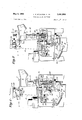
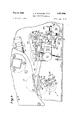
FIGS. 8 through 10 are plan views, partly in section and partly broken away, of linkage and control mechanism of the illustrative machine showing the various positions of the elements; (a) prior to the start of, (b) at the start of, and (c) during the scouring operation, respectively;
FIGS. 11 and 12 are side and end views respectively of the mechanism shown in FIGS. 8 to 10; and
FIG. 13 is a diagram of the pneumatic circuitry of the machine.
The invention is shown embodied in an automatic heel scouring machine but it is to be understood that the particular machine is shown for illustrative purposes only. The invention may be embodied as well, for example, in a heel trimming machine or any other machine for performing peripheral operations, such as inking, etc., on heels.
General features FIG. 1 shows the front of the machine as it appears to an operator prior to a shoe being placed in it. The machine comprises a main body 2 supported on an appropriate frame structure 4. Various portions of the operating mechanism of the machine are mounted both in the body 2 and the supporting'frame structure 4.
The more prominent elements of the machine include a tool, illustrated as a scouring wheel 6, mounted for rotation about an aXis A, in a scouring wheel arm generally indicated at 8 which swings about a substantially vertical axis A passing through an arm housing 10. A dust hood 11 is located near the wheel 6. A partially completed shoe S on a last L (FIG. 3) is mounted on a jack 12 for both vertical positioning movement and rotation relative to the Wheel 6. The handles of the two manually operated start valves V1 and V2, are located on the upper front portion of the body 2. Both valve handles must be depressed by the operator to set the machine in operation. Motor control switches collectively designated 13 are also conveniently located on the front of the body 2.
In operative position (as shown in FIG. 3) the tread surface of a heel H of the shoe S mounted on the jack 12 is engaged by a heel clamp 14 having a clamp post 15 mounted at the free end of a pivotal clamp arm 16.
Shoe supportinlg jack and heel clamp The shoe supporting jack 12 and the heel clamp 14 are substantially similar to those disclosed in the above-identified Stanton et al. application and are described only briefly herein to correlate them with other elements of the machine. Reference may be had, however, to the aboveidentified application for details of construction not herein described.
With particular reference to FIGS. 4 and 5, the jack 12 includes a shaft or jack post 20 mounted for vertical movement in the machine as well as for oscillating rotative motion. Vertical motion is obtained from an air motor 22 also known as the jack post cylinder pivotally secured to a bracket 24 on the frame 4 with its piston rod connected to a bell crank lever 28 which is pivoted on a bracket 30 also depending from the frame. The opposite end of the bell crank lever 28 takes the form of a clevis 32 which is received within an annular slot 34 at the lower end of the rotatable jack post 20. By the pressurization and depressurization of the jack post cylinder 22 the jack post 20 as well as the jack mechanism 12 are caused to ascend and descend toward and away from the heel clamp 14.
The heel clamp 14 cooperates with the jack 12 to support the shoe during scouring and is mounted at the free end of the aforementioned clamp arm 16 operated by a clamp arm cylinder 17 connected by a clevis 19 (FIG. 3). The heel clamp includes at the lower end of the clamp post 15 a rotatable heel engaging member 36 which is adjustable heightwise with respect to the arm 16 in accordance with the height of the heel H of the particular shoe being operated on. When a shoe S which has been placed on the jack 12 either manually or by automatic means not forming a part of this invention rises into position, its heel H engages the member 36 urging the clamp post 15 into an upper locked position in the manner described in the aforementioned Stanton et al. application. Upward locking movement of the clamp post 15 actuates a limit valve 6B (FIG. 3) located within the clamp arm 16. The plunger 37 of the valve 6B engages a small bell crank 39 engageable within a slot 41 in an internal vertically movable portion of the clamp post 15. The heel clamping member 14 permits the shoe to rotate about the jack axis A,- as the jack is rotated but after locking prohibits movement along such axis. Oscillating rotative motion is imparted to the jack in substantially the same manner as disclosed in the aforementioned Stanton et al. application and includes a gear 38 fixed to the jack shaft 20 which meshes with and is driven by a gear segment 40. The gear segment 40 pivots on a fixed vertical shaft 42.
Oscillating rotative motion is imparted to the gear segment 40 from a slide 44 which reciprocates in a guideway 46 secured to the machine frame, a roller 47 on the slide 44 being engageable within a slot 48 in an arm 50 of the gear segment 40. The slide 44 receives reciprocating motion from an air motor 45 also known as the jack rotation cylinder. For purposes hereinafter to be described, the slide 44 in its various positions actuates limit valves 6D, 6C and 6F also to be described in greater detail hereinafter. All of the foregoing mechanism is substantially similar in construction and operation to the equivalent mechanism disclosed in the Stanton et al. application.
Tool and its operating mechanism Referring particularly to FIGS. 6 and 7 and also with reference to FIGS. 2 and 3, the tool, illustrated as a scouring wheel 6, and its operating mechanism will now be described. The wheel comprises a fiat cylindrical resilient disk 60 covered with replaceable abrasive material such as sandpaper or emery cloth. The wheel 60 is secured to a shaft 62 for rotation in an arm 64 forming part of the aforementioned scouring wheel arm 8. Rotat1on is imparted to the shaft 62 by a pulley 66 deriving its power from a V-belt 68 the opposite end of which passes around the end of a pulley 70 splined to a vertical shaft 71 rotatable within a hollow shaft 72 passing through the wheel arm housing 10. The arm 64, pulleys 66, 70, etc., are protected by a sheet metal cover 73 secured to the upper portion of the arm 64.
The arm 64, or tilt arm as it is also called, is an irregularly shaped member the right-hand (as viewed in FIG. 6) end of which is bifurcated and pivotally mounted on studs 74, 76 received in a boss 78 formed as an extension on a hub 80 to which the shaft 72 is attached. Also secured to the hub 80 and rotatable as a unit about the axis A is a rigid arm 82 of irregular shape. At the free end of the arm 82 is an upstanding stud 84. A compression spring 86 surrounds the stud 84 and is compressed within a cap 90 in the arm tilt 64.
The hub 80 and the rigid arm 82 are capable of swinging motion only in a substantially horizontal plane about the axis A and against a stop 83 whereas the arm 64 is capable of the same motion but in addition is tiltable in a substantially vertical plane about the axes of the studs 74, 76. The tilting arm 64 is urged toward the upper or broken line (FIG. 7) position by the spring 86.
An air motor or main ann cylinder 92 is fixed to a central portion of the rigid arm 82 and includes a plunger 94 (FIGS. 6 to 8). The free end of the plunger is engagable with an upstanding leg 96 of an irregular but substantially T-shaped member 98 which is pivoted in trunnions 100 on the rigid arm 82. Another leg 102 of the member 98 is pivotally secured by a link 104 to the tilting arm 64. A flat 106 is formed on the opposite horizontal leg 108 of the member 98. Normally, the tilt arm 64 is urged upwardly toward the broken line position of FIG. 7 away from the rigid arm 82 by the spring 86. At full elevated position of the tilt arm 64 the fiat 106 on the member 98 bottoms against the arm 82 when the main arm cylinder 92 is depressurized. When, however, the cylinder 92 is pressurized, the member 98' is pivoted to the full line position, shown in FIG. 7, whereby the tilt arm 64 is drawn downwardly against the force of the spring 86.
A feeler member seen in perspective in FIG. 2, is mounted for pivotal movement at the free end of the tilt arm 64 in close proximity to the scouring Wheel 60. The feeler member 120 includes a curved feeler plate 122 which is engageable within the rand crease of a shoe to sense heightwise variations and to cause the tilt arm 64 and hence the scouring wheel to follow those variations about the periphery of the heel. The feeler plate 122 is secured to the free end of an irregularly shaped feeler arm 124 the opposite end of which mounts a stud 126 which is rotatively and adjustably received in a sleeve 128 fitted in a boss 130 forming part of the tilt arm 64. A pinned collar 132 holds the stud 126 in the sleeve 128. A bill binder 134 in the boss locks the stud 126 and sleeve 128 in the selected position in the boss 130. However, the feeler and tilt arm 64 are locked together for tilting motion about the axis of the studs 74, 76. A spring tensioned between a stud 142 on the tilt arm 64 and a plate 143 on the arm 124 normally urges the feeler gauge 120 in a counterclockwise direction about the axis of the stud 126 and into the position shown in FIG. 6, with the feeler plate 122 extending outwardly a slight distance from the periphery of the wheel 60. A stop screw 144 in the plate 143 engages a boss 145 on the arm 64 at this time. Upon engagement with the shoe, as will be described hereinafter, and as seen in FIG. 3, the feeler plate 122 will enter and follow the rand crease, without imparting horizontal motion to the tilt arm 64 or the scouring wheel '60 while the wheel 60 is maintained in engagement with the periphery of the heel. However, heightwise variations in the rand crease and accordingly the heel measured along the jack axis A; are transmitted from the feeler guage 120 to' the scouring wheel 60 through the floatingaction of tilt arm 64.
Referring next to FIGS. 8-12, the means for swinging the tool arm 8 will now be described. The hollow shaft 72, which, in effect, is a rigid extension of the hub 80 and the tool arm 8 and passes downwardly through the tool arm housing and is capable of swinging motion only about the axis A Coaxially within the hollow shaft 72 is the shaft 71 which transmits rotary motion from an electric motor M to the pulley 70 which in turn transmits motion to the scouring wheel 60 by pulley and belt means above described.
Securely clamped to the lower end of the hollow shaft 72 which is journaled in the housing 10 against axial movement by bearings 152 (FIG. 11) is an arm 154, best seen in plan view in FIGS. 8-10 and in elevation in FIG. 12. A plate 156 is secured to the free end of the arm 154 and depending from the arm is a smaller plate 158. The arm 154 and hence the ,hollow shaft 72 are urged in a counterclockwise direction about the axis A by a tension spring 160 which isconnected to the plate 156 by a cable 162 passing around pulleys 164 and 166. This urges the wheel 60 into engagement with the heel H. The tension of the spring-160 may be adjusted in any convenient manner byun ea ns not shown, such as by mechanism for adjusting the distance between pulleys 164 and 166. I
Limited motion is imparted through the tool arm 8 to the scouring wheel 60 from the master cam C by mechanism now to be described and for purposes which will become more evident hereinafter. Cam follower means comprising rollers 172, 174 (FIGS. 8-10) are mounted at the free end of a cam follower arm 176 which is secured to a hub 178-pivotally mounted for movement about a vertical axis on a'stud 180 fixed within the machine frame structure 2. Also secured to the hub 178 and movable with the cam follower arm 176 is an arm 181, these elements acting as a bell crank lever. At its free end, the arm 1 81 supports a depending boss 182 which freely receives a pin 184- ('FIG. 12) depending from an air cylinder also known as the control lever cylinder 186. Thus, while the cylinder 186 is supported by the arm 181 and hence is rotatable as a unit about the stud 180, it is also pivotal with respect to the arm 181 about the axis of the pin184.
Fixed to the cam followerarm 176 a short distance from the hub 178 is a boss 19 0 carrying a vertical stud 192. A bell crank lever194 is pivoted on the stud 192 and includes an upper arm 196 mounting at its free end a roller 198 engageable with the plate 156 of the arm 154. The lower arm 200 of the bell crank lever 194 is pivotally secured by a clevis 202 to the piston rod 204 of the aforementioned control lever cylinder 186. While it will be described in more detail hereinafter, it will be noted that when the piston rod 204 is extended out of the air cylinder 186 it causes the bell crank 194 to be urged in a clockwise direction as viewed in FIGS. 8-10, placing the arm 154 in the position shown in FIG. 8 against the force of the tension spring 160.
Also pivoted on the stud 192 in the boss 190 on the cam follower arm 176 is a second bell crank lever 210, an arm 212 of which mounts at its free end a limit switch 6E. The plunger 216 of the switch is engageable with the small plate 158 connected to'the arm 154. The second arm 220 of the bell'crank 210 is attached to an adjusting rod 222 (FIG. 8) which extends from and is threaded into a boss 224 firmly secured to the arm 181 extending from the cam follower arm boss 178. The adjusting rod 222 is extensible axially from the boss 224 by rotation of a hand wheel 226. Rotation of the wheel 226 adjusts the position of the limit switch 6E through the action of the bell crank 210, which is urged in a counterclockwise direction, as viewed in FIG. 8, about the stud 192 by a tension spring 228. The extent of counterclockwise movement of the bell crank 194 about the stud 192 is limited by a boss 230 depending from the arm 200 of the bell crank 194 which engages the arm 220 of the bell crank 210 (FIGS. 9 and 10).
As in the above-identified Stanton et al. application, latch mechanism is associated with the slide 44 which is employed with other mechanism to cause the jack post to oscillate. As seen in FIGS. 8 and 10, limit switches 6D and 6F are located on the guideway 46 which mounts the slide 44. These switches are actuated when the slide 44 is in its extreme rightand left-hand positions, respectively.
A latch 250 having the general form of a bell crank is pivotally secured to the guideway 46 by a pin 252. The right-hand end of the bell crank latch 250 is provided with a nose 254 which is engageable with a sloping surface 256 on the left-hand end of the slide 44. The bell crank latch 250 is normally urged into engagement with the surface 256 by a tension spring 260 which is secured to its leg 262 and to 'a portion of the machine frame 264. Also engageable with the leg 262 of the latch 250 is a plunger 266 of an air cylinder 268 mounted on the frame portions 264 and also known as the stop arm cylinder.
A small lever 270 is pivoted on the bell crank latch and is also engageable with the surface 256 of the slide 44. The opposite end of the lever 270 is engageable with the plunger 272 of a limit switch 6C secured on the lower arm of the bell crank 250. The plunger 272 of the switch 6C in off position normally urges the smaller lever 270 in a clockwise direction against a stop 274.
When the double acting air motor 45, also known as the jack rotation cylinder, pulls the slide 44 to the right as viewed in FIG. 8, and the stop arm cylinder 268 is depressurized, the surface 256 engages beneath the latch 254 and the gear segment 40 (and hence the jack 12) is then stopped in dead center position whereby the shoe may be loaded onto or off the jack 12. The small lever 270 also engaging the surface 256 depresses the plunger 272 of the limit switch 6C.
When, however, the stop arm cylinder 268 is actuate or pressurized its plunger 266 pivots the latch 250 out of engagement with the surface 256 on the slide 44 and the jack rotation cylinder 45 is free to move the slide '44 further to the right or into the FIG. 8 position rotating the jack accordingly. Release of the latch 250 from the slide also releases the small lever 270 permitting the plunger 272 to extend out of the limit switch 6C. The operation of the various limit switches will be explained in more detail hereinafter.
The master cam As best seen in FIGS. 8-11, the master cam C is firmly attached to the jack shaft 20 being keyed and spaced from the gear38 by a collar 280 (FIG. 11). The operative surface 282 of the cam C has a generally heel shaped cross section as seen in FIGS. 8-10 and increases height wise of the axis Aj of the jack shaft 20 in substantially geometric proportions similar to the master cam of the above-identified Stanton et al. application. Firmly secured to and forming part of the cam C is a substantially wing shaped member 284 having lobes 2-86 and 288 which extend outwardly from the surface 290 of the master cam C which approximates the breast line. The function of the Wing member 284 is to maintain the scouring wheel 60 out of engagement with the heel at the beginning and end of the scouring operation, i.e., when the jack is not rotating.
Operation of the machine With reference to the pneumatic diagram of FIG. 13 and to the other figures hereinabove referred to, the operation of the illustrative machine in a heel scouring cycle will now be described.
Before the operating cycle begins the various machine elements occupy the positions shown in FIGS. 1, 4, 11 and 12. Upon connecting the machine to a source of pressurized air the pneumatic elements assume the original or idle positions shown in the pneumatic diagram of FIG. 13. The operator places a shoe S, having a previously trimmed heel, bottom upwardly on the jack 12 with the toe pointing toward him as he stands facing the machine in the direction shown in FIG. 1. The breast line of the shoe and the corresponding line 290 (FIG. 8) of the cam C faces the operator at this time. The machine may also be loaded and unloaded by automatic transporter means not forming a part of this invention.
The motor M is turned on and the handles of both of the manual start values V1 and V2 are depressed, it being required that both valves be actuated to start the machine for obvious reasons of operator safety. Upon actuation of the start valves V1 and V2, a 4-way valve A (FIG. 13) is shifted causing pressurized air to be supplied to the limit valve 6B which is located in the clamp arm 16 (FIG. 3). This valve is normally held in the position shown in FIGS. 3 and 13 by its spring whereupon its plunger 37 holds the small bell crank 39 in its lowered position within the slot 41 ready to be actuated by subsequent upward locking movement of the clamp post 15. Air is also exhausted from the piston rod end of the jack post cylinder 22 (FIG. 4) through the valve 10A. Simultaneously, the stop arm cylinder 268 on the jack operating slide 44 (FIGS. 8 and 10) is pressurized with its rod 266 pivoting the latch 250 in a counterclockwise direction as seen in FIG. 8 which unlatches the slide 44 permitting it to be moved by the jack rotation cylinder 45 to the right or toward the FIG. 8 position when the cylinder 45 becomes pressurized. When the latch 250 is disengaged from the slide 44 the limit valve 6C (FIG. 8) is also released causing 3-way valve 14A (FIG. 13) to shift to the spring held position. This in turn causes the jack rotation cylinder 45 to become pressurized and begin movement of the slide 44 to the right, as viewed in FIG. 8 or left as viewed in FIG. 13, rotating the jack and shoe counterclockwise as viewed by the operator. Also at this time the clamp arm cylinder 17 (FIG. 3) is pressurized causing the heel clamp 14 to begin swinging clockwise toward a position of vertical alignment above the fixed jack axis A During the foregoing the scouring wheel 60 is rotating but is out of engagement with the heel.
As the heel clamp 14 is being swung over to locate the heel engaging member 36 above the jack axis A;, the jack rotation cylinder 45 is moving the slide 44 to the right and turning the shoe counterclockwise. When slide 44 reaches the end of its stroke, limit switch 6D is actuated. Completion of the stroke of the clamp arm cylinder 17 actuates the limit valve 6A at the rear of the clamp arm 16 (FIG. 1). The machine elements are then in the FIG. 8 position with the toe of the shoe pointing to the operators right.
When the limit valve 6A is actuated at the end of the swinging movement of the clamp arm it operates 3-way valve 5A (FIG. 13) which pressurizes the jack post cylinder 22. This causes the jack post and the shoe to rise moving from the FIG. 4 toward the FIG. 5 position. The heel engaging member 36 on the clamp arm post 15 then being aligned with the jack is engaged by the tread surface of the heel H. This moves the clamp arm post 15 upwardly into locking position which causes limit valve 6B (located in the clamp arm 16) to be tripped which in turn causes pressurized air to be supplied through 4-way valve (FIG. 13) and the limit valve 6D (which was actuated when the slide 44 reached its right-hand position) to the pilot of 4-way valve 9B. This causes the piston rod 204 of the control lever cylinder 186 to retract from the FIG. 8 to the FIG. 9 position under the force of the tension spring 160. It will be noted that in the idle or start position the control lever cylinder 186 was pressurized with its piston rod 204 extended to the FIG. 8 position which maintained the arm 154 (FIG. 8), and hence the scouring wheel 60, in the FIG. 4 or the upper dotted position shown in FIG. 8, i.e. with the wheel away from the shoe.
When the arm 154 moves from the FIG. 8 to the FIG. 9 position, the limit valve 6E on the bell crank lever 210 is actuated directing air to the pilot of 4-way valve 9D (FIG. 13) which shifts 4-way valve 10B. Shifting of valve 10B causes the jack rotation cylinder to reverse moving the slide 44 toward the left thus rotating the shoe clockwise as represented by the cam C moving from the FIG. 9 toward the FIG. 10 position. Shifting of valve 9D also permits exhaust of air from the cylinder 92 located within the scouring arm 8 (FIG. 7) to permit the tilt arm 64 and hence the scouring wheel 60 to rise under the influence of the small spring 86. At the time the scouring wheel 60 moves into engagement with the heel of the shoe, the shoe is being rotated clockwise as will be explained more fully hereinafter.
The feeler 122 extending from beneath the periphery of the scouring wheel 60 first engages the shoe in the crease between the outsole and upper as seen in FIGS. 3 and 5, and since the scouring wheel 60 and the feeler are then free to rise, the feeler 122 moves inwardly and upwardly into position followed closely by the scouring wheel 60 engaging the then rotating shoe. The feeler and wheel maintain a floating relationship to the shoe throughout the trimming cycle following variations in height about the heel periphery.
It will be noted that the cam follower 174 (FIGS. 8 to 10) is in engagement with the wing or lobe 286 on the cam C at the beginning of the clockwise rotation of the cam and shoe. This prevents premature engagement of the scouring wheel with the heel or sole edge and etfectively retards engagement until after the shoe has begun to rotate. As the follower 174 leaves the lobe 286 and engages the periphery of the heel shaped portion of the cam C the then rotating scouring wheel 60 engages the shoe toewardly of the breast line making initial contact approximately /2" ahead of the breast line at the edge of the sole. Since the shoe is then rotating the relative movement between the scouring wheel and the shoe produces a relatively uniform velocity of scouring cut which continues as the wheel engages progressively heelward past the breast line of the shoe and around the periphery of the heel. Were it not for the provision of the lobes 286 and 288 on the cam C, engagement between the scouring wheel and the shoe could take place before the shoe began to rotate and at the conclusion of its rotation and could produce an undesired depression in the heel or sole rather than a smoothly blended profile.
The scouring cut, which in effect removes very little stock, begins when the various mechanisms are in the positions shown in FIG. 9. The scouring operation is half completed when the cam C has been rotated to the FIG. 10 position. During the scouring operation the wheel 60 is held in engagement with the heel by the force of the spring 160. It will be noted in FIG. 10 that a gap exists between the roller 198 on the 'bell crank 194 and the plate 156 located on the arm 154 whereby the scouring arm and hence the wheel are not under the control of the cam C. The heel, having been previously trimmed with an accurate periphery is its own guide for the scouring wheel, the feeler only guiding the wheel in an up and down direction with respect to the wheel.
The cam C again takes over control when it has been rotated to a position (not herein shown) where the follower 172 rides up on the lobe 288 whereby, through the various linkage mechanisms shown in FIG. 10, the arm 154 begins to move from the solid to the broken line position. At this time the jack rotation cylinder 45 is approaching the end of its stroke which terminates when the limit valve 6F is actuated by being engaged by the slide 44. The scouring operation then has been completed.
At this time 4-way valve 9C is automatically shifted and pressurized air is supplied to the 4-way valve 10B. 4- way valves 9B and 10A are also returned then to their original or idle positions. The shifting of valve 10A causes the clamp arm cylinder 17 to reverse. It also causes pressurized air to be released from the piston rod end of the jack post cylinder 22. The shifting of valve 103 reverses the movement of the jack rotation cylinder 45 causing it to move again toward the idle position wherein the slide 44 is again engaged and latched by the latch 250. The shifting of valve 9B causes the control lever cylinder 186 to move to its original or extended position swinging the scouring wheel 60 away from the shoe.
At the idle position of the jack rotation cylinder 45, limit valve 6C is again actuated by the engagement of the latch 250 with the slide 44. This action removes pressurized air from the valve 10B and applies pressurized air to the piston rod end of the jack post cylinder 22, causing the jack to descend whereby the machine is ready to operate upon the next shoe.
Having thus described our invention, what we claim as new and desire to secure by Letters Patent of the United States is:
1. In a machine for automatically performing finishing operations upon the heel portion of a shoe, a jack for mounting the shoe on an axis substantially normal to the tread surface of the heel, a tool movable in a direction transversely of said axis and engageable with the shoe, a feeler member engageable with the shoe and controlling the vertical position of the tool means for rotating the jack and shoe about said axis, means for urging the tool into and out of multi-directional yielding operative engagement with the shoe, and means for causing the tool to engage the shoe only after the shoe has begun to rotate and to disengage the shoe before it has completed rotation.
2. In a machine for automatically performing finishing operations upon the heel portion of a shoe, a jack for mounting the shoe on an axis substantially normal to the tread surface of the heel, a tool movable in a direction transversely of said axis and engageable with the shoe, a feeler member engageable with the shoe and controlling the vertical position of the tool means for rotating the jack and shoe about said axis, and means for urging the tool yieldingly into engagement with the edge of the shoe sole in the shank area toewardly of the breast line only after the shoe has begun to rotate and for disengaging the tool from the sole in the shank area toewardly of the breast line at the opposite side after the entire heel periphery has been presented to the tool and before rotation stops.
3. In a machine for automatically performing finishing operations upon the heel portion of a shoe, a jack for mounting the shoe on an axis substantially normal to the tread surface of the heel, a tool movable in a direction transversely of said axis and engageable with the heel, a feeler member engageable with the shoe and controlling the vertical position of the tool means for rotating the jack and shoe about said axis, a cam on said jack, motion transmitting means operatively connecting the cam to the tool for controlling the tool for movement into and out of engagement with the shoe, and lobe members on said cam for causing the tool to engage the shoe only after the shoe has begun to rotate and to disengage the shoe before it has completed rotation.
4. In a machine for automatically performing finishing operations upon the heel portion of a shoe, a jack mounting for the shoe on an axis substantially normal to the tread surface of the heel, a tool movable in a direction transversely of said axis and engageable with the heel, a feeler member engageable with the shoe and controlling the vertical position of the tool means for rotating the jack and shoe about said axis, a cam rotatable with said jack and simulating the peripheral shape of the heel portion of the shoe, motion transmitting means operatively connecting the cam to the tool comprising both rigi'd mechanical cam follower linkage and yieldable control means movable with said mechanical linkage, and means for rendering said mechanical linkage operative to place the tool in close proximity to the shoe and for rendering said yieldable control means operative to place the tool in engagement with the shoe.
5. In a machine for automatically performing finishing operations upon the heel portion of a shoe, a jack for mounting the shoe on an axis substantially normal to the tread surface of the heel, a tool movable in a direction transversely of said axis and engageable with the heel, a feeler member engageable with the shoe and controlling the vertical position of the tool means for rotating the jack and shoe about said axis between predetermined start and stop positions to present to the tool the entire heel area of the shoe between points on the edges of the sole in the shank area toewardly of the breast line, spring biased means to urge the tool into yielding engagemnet with the shoe to perform the finishing operation, and cam controlled means for rendering said spring biased means operative only after the shoe has begun and before it has completed rotation.
6. In a machine for automatically performing finishing operations upon the heel portion of a shoe, a jack for mounting the shoe on an axis substantially normal to the tread surface of the heel, a tool movable in a direction transversely of said axis and engageable with the heel, a feeler member engageable with the shoe and controlling the vertical position of the tool means for rotating the jack and shoe about said axis between predetermined start and stop positions, automatic means for placing the tool in yielding operative engagement with the shoe, signalling means eifective only after the start and stop position of jack rotation for rendering said automatic means effective.
7. In a machine for automatically performing finishing operations upon the heel portion of a shoe, a jack for mounting the shoe bottom side upwardly on an axis substantially normal to the tread surface of the heel, a tool movable in a direction transversely of said axis and engageable with the shoe, means for rotating the jack and shoe about said axis, means for urging the tool into and out of yielding operative engagement with the shoe, a feeler adjacent the tool engageable with the shoe to control the vertical position of the tool, means supporting the tool and feeler for up and down floating movement with respect to the shoe bottom to follow variations in height about the heel portion, means maintaining said floating means in a lower inoperative position as the tool approaches the shoe, and means for releasing said maintaining means after the shoe has begun to rotate.
8. In a machine for automatically performing finishing operations upon the heel portion of a shoe, a jack for mounting the shoe on an axis substantially normal to the tread surface of the heel, a tool movable in a direction transversely of said axis and engageable with the heel, means for rotating the jack and shoe about said axis between predetermined start and stop positions to present to the tool the entire heel area of the shoe between points on the edges of the sole in the shank area toewardly of the breast line, spring biased means to urge the tool into yielding engagement with the shoe to perform the finishing operation, cam controlled means for rendering said spring biased means operative only after the shoe has begun and completed rotation, at feeler adjacent the tool engageable with the shoe to control the height of the tool, means supporting the tool and feeler for up and down floating movement with respect to the shoe bottom to follow variations in height about the heel portion, means maintaining said floating means in a lower inoperative position as the tool approaches the shoe, and means for releasing said maintaining means after the shoe has begun to rotate.
9. In a machine for automatically performing finishing operations upon the heel portion of a shoe, a jack for mounting the shoe on an axis substantially normal to the tread surface of the heel, a tool movable in a direction transversely of said axis and engageable with the heel, means for rotating the jack and shoe about said axis, a cam on said jack, motion transmitting means operatively connecting the cam to the tool for controlling the tool for movement into and out of engagement with the shoe, lobe members on said cam for preventing the tool from engaging and disengaging the shoe until after the shoe has begun and completed rotation respectively, a feeler adjacent the tool, a feeler member engageable with the shoe and controlling the vertical position of the tool, means supporting the tool and feeler for up and down floating movement with respect to the shoe bottom to follow variations in height about the heel portion, means maintaining said floating means in a lower inoperative position as the tool approaches the shoe, and means for releasing said maintaining means after the shoe has begun to rotate.
10. In a machine for automatically performing finishing operations upon the heel portion of a shoe, a jack for mounting the shoe on an axis substantially normal to the tread surface of the heel, a tool movable in a direction transversely of said axis and engageable With the shoe, means for rotating the jack and shoe about said axis, means for urging the tool yieldingly into engagement With the edge of the shoe sole in the shank area toewardly of the breast line only after the shoe has begun to rotate and for disengaging the tool from the sole in the shank area toewardly of the breast line at the opposite side after the entire heel periphery has been presented to the tool and before rotation stops, a feeler adjacent the tool, a feeler member engageable with the shoe and controlling the vertical position of the tool, means supporting the tool and feeler for up and down floating movement with respect to the shoe bottom to follow variations in height about the heel portion, means maintaining said floating means in a lower inoperative position as the tool approaches the shoe, and means for releasing said maintaining means after the shoe has begun to rotate.
References Cited UNITED STATES PATENTS 2,948,906 8/1960 Pulsifer 1287 3,088,146 5/1963 Forma 12-87 3,235,893 2/1966 Alderman l2--87 3,299,455 1/ 1967 Harrington 1287 PATRICK D. LAWSON, Primary Examiner.
Applications Claiming Priority (1)
| Application Number | Priority Date | Filing Date | Title |
|---|---|---|---|
| US46265765A | 1965-06-09 | 1965-06-09 |
Publications (1)
| Publication Number | Publication Date |
|---|---|
| US3441966A true US3441966A (en) | 1969-05-06 |
Family
ID=23837273
Family Applications (1)
| Application Number | Title | Priority Date | Filing Date |
|---|---|---|---|
| US462657A Expired - Lifetime US3441966A (en) | 1965-06-09 | 1965-06-09 | Heel finishing machines |
Country Status (2)
| Country | Link |
|---|---|
| US (1) | US3441966A (en) |
| GB (1) | GB1151923A (en) |
Cited By (2)
| Publication number | Priority date | Publication date | Assignee | Title |
|---|---|---|---|---|
| CN103734999A (en) * | 2013-10-21 | 2014-04-23 | 东莞市意利自动化科技有限公司 | Tape machine |
| CN108852248A (en) * | 2018-06-12 | 2018-11-23 | 浙江理工大学 | A kind of automatic shoe washing machine and its method for washing shoe |
Citations (4)
| Publication number | Priority date | Publication date | Assignee | Title |
|---|---|---|---|---|
| US2948906A (en) * | 1958-07-02 | 1960-08-16 | United Shoe Machinery Corp | Machines for trimming shoe-attached heels |
| US3088146A (en) * | 1960-06-08 | 1963-05-07 | Superior Shoe Company Inc | Machine for operating on shoes |
| US3235893A (en) * | 1963-05-14 | 1966-02-22 | United Shoe Machinery Corp | Heel finishing machines |
| US3299455A (en) * | 1964-10-26 | 1967-01-24 | Wolverine Shoe & Tanning Corp | Heel and sole trimmer |
-
1965
- 1965-06-09 US US462657A patent/US3441966A/en not_active Expired - Lifetime
-
1966
- 1966-06-08 GB GB25448/66A patent/GB1151923A/en not_active Expired
Patent Citations (4)
| Publication number | Priority date | Publication date | Assignee | Title |
|---|---|---|---|---|
| US2948906A (en) * | 1958-07-02 | 1960-08-16 | United Shoe Machinery Corp | Machines for trimming shoe-attached heels |
| US3088146A (en) * | 1960-06-08 | 1963-05-07 | Superior Shoe Company Inc | Machine for operating on shoes |
| US3235893A (en) * | 1963-05-14 | 1966-02-22 | United Shoe Machinery Corp | Heel finishing machines |
| US3299455A (en) * | 1964-10-26 | 1967-01-24 | Wolverine Shoe & Tanning Corp | Heel and sole trimmer |
Cited By (3)
| Publication number | Priority date | Publication date | Assignee | Title |
|---|---|---|---|---|
| CN103734999A (en) * | 2013-10-21 | 2014-04-23 | 东莞市意利自动化科技有限公司 | Tape machine |
| CN103734999B (en) * | 2013-10-21 | 2015-07-01 | 东莞市意利自动化科技有限公司 | Strip attaching machine |
| CN108852248A (en) * | 2018-06-12 | 2018-11-23 | 浙江理工大学 | A kind of automatic shoe washing machine and its method for washing shoe |
Also Published As
| Publication number | Publication date |
|---|---|
| GB1151923A (en) | 1969-05-14 |
Similar Documents
| Publication | Publication Date | Title |
|---|---|---|
| US3441966A (en) | Heel finishing machines | |
| US2730733A (en) | Heel lasting machines | |
| US3165771A (en) | Apparatus for lasting footwear | |
| US3019461A (en) | Sole rounding machines | |
| US3163031A (en) | Shoe bottom roughing machines | |
| US3235893A (en) | Heel finishing machines | |
| US2903723A (en) | Adjustable sole gauge for rib applying machine | |
| US3000024A (en) | Shoe machine | |
| US3267705A (en) | Automatic roughening machines | |
| US3518851A (en) | Control means for use with a positively guided tool | |
| US2385482A (en) | Heel breasting machine | |
| US2556410A (en) | Toe lining trimming machine | |
| US3325838A (en) | Insole rib attaching machines | |
| US2693608A (en) | Sole rounding and channeling machine | |
| US3443269A (en) | Top line pressing machine for shoe uppers | |
| US2582975A (en) | Shoe toe lining trimming machine | |
| US2302019A (en) | Machine for operating on shoes | |
| US1417540A (en) | Work support | |
| US1416707A (en) | Cutting machine | |
| US1288521A (en) | Machine for operating upon heels. | |
| US3075210A (en) | Shoe holding jacks | |
| US2679656A (en) | Machine for pressing a wrapper against the edge of a shoe sole | |
| US2199512A (en) | Toe-trimming machine | |
| US2715739A (en) | Binding applying and cutting machine | |
| US2720668A (en) | Trimming machine |