US3445939A - Apparatus for the circulation of a gaseous medium through a drying channel - Google Patents
Apparatus for the circulation of a gaseous medium through a drying channel Download PDFInfo
- Publication number
- US3445939A US3445939A US664403A US3445939DA US3445939A US 3445939 A US3445939 A US 3445939A US 664403 A US664403 A US 664403A US 3445939D A US3445939D A US 3445939DA US 3445939 A US3445939 A US 3445939A
- Authority
- US
- United States
- Prior art keywords
- wood
- drying
- air
- package
- channel
- Prior art date
- Legal status (The legal status is an assumption and is not a legal conclusion. Google has not performed a legal analysis and makes no representation as to the accuracy of the status listed.)
- Expired - Lifetime
Links
Images


Classifications
-
- F—MECHANICAL ENGINEERING; LIGHTING; HEATING; WEAPONS; BLASTING
- F26—DRYING
- F26B—DRYING SOLID MATERIALS OR OBJECTS BY REMOVING LIQUID THEREFROM
- F26B15/00—Machines or apparatus for drying objects with progressive movement; Machines or apparatus with progressive movement for drying batches of material in compact form
-
- F—MECHANICAL ENGINEERING; LIGHTING; HEATING; WEAPONS; BLASTING
- F26—DRYING
- F26B—DRYING SOLID MATERIALS OR OBJECTS BY REMOVING LIQUID THEREFROM
- F26B2210/00—Drying processes and machines for solid objects characterised by the specific requirements of the drying goods
- F26B2210/16—Wood, e.g. lumber, timber
Definitions
- the present invention relates to an apparatus for the circulation of, a, gaseous medium through a drying channel, substantially intended for a substantially continuous feeding therethrough of wood which with its longitudinal direction perpendicular to the channel is stacked in batches on conveying means feeding the wood batches by steps in the longitudinal direction of the channel, and wherein the channel by an intermediate space is divided in its longitudinal direction into two sections in which the drying medium, in one section flows in counter-current, to the feed direction of the wood and in the other section in the feed direction of the wood.
- Wood to be dried usually is piled batchwise to packages, with intermediate ribs (crossers) disposed perpendicular to the longitudinal direction of the wood for rendering the drying medium possible to circulate about the wood when the drying medium is blown against a wood package perpendicularly to the longitudinal direction of the wood.
- the wood pieces are not all of the same length but, have. a certain spread with respect to their length, the wood, quantity per unit of volume varieswithin a package in the longitudinal direction of the wood and, as a rule, in such a manner, that the compactness of the wood is greatest in the centre of the package and smallest atits two ends.
- the latter also. applies to. such cases when the wood is piled in piling machines and the wood; pieces thereby are automatically drawn level to the. package ends, so that every second *wood piece is drawn level at one end of the. package and every second wood piece at the opposite. end.
- a wood package to be dried comprises a correspondingly greater amount of water in its centre than at its ends.
- the initial flow conditions upon the entrance of the drying air into the. first package must be arranged such, that. a greater air quantity is blown through the drying channel in its centre than farther out to its side walls, in order thereby to effect the greater evaporation required in the centre of the channel so that. a uniform drying of the wood in its longitudinal direction is obtained.
- The, solution of the problem offered by the invention is characterized in that in the longitudinal side walls of the channel, symmetrically with respect, to. the central longitudinal vertical plane of the channel, axial fans are mounted with their shafts substantially perpendicularly to said plane and adapted to blow the drying medium into the channel in the intermediate space between said two sections.
- the impulse. flow produced by the axial fans will bev concentrated to the centre; of the. channel and, owing to the symmetry, be deflected at a. right angle in the longitudinal direction of the drying channel, thereby bringing about the desired effect.
- the air ro by the symmetric counterflow, the air ro.
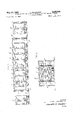
- FIG. 1 shows a longitudinal section seen from above of a drying channel in which the invention is applied
- FIGS. 2 and 3 are longitudinal and transverse sectional views of the drying channel, taken on the lines 2-2 and 33 respectively of FIG. 1, and
- FIGS. 4 and 5 are plots showing the distribution of wood in average packages of 18 and 21 it. lengths respectively in Swedish saw mills.
- FIG. 1 a number of wood batches I-al'so called wood packages-wait outside of the receiving door 2- of a wood dryer 3.
- the wood is piled on cars which can travel on rails 4' through the dryer 3.
- the dryer 3 comprises a central drying channel for wood and drying air return passages 5, 6 placed on the side.
- the drying-chanml is divided into a first and a second section which are separated by an intermediate space 7'.
- axial fans '9, 10 are arranged in pairs in full symmetry with respect to the central longitudinal vertical plane of the channel.
- In the first section of the channel three wood packages 11, and in the second channel section four packages 12 are located.
- a free space, 13 isv provided, and between the packages 12 in the second channel section and the discharge door 14 of thedryer 3 a free space 15 is provided. Outside of the discharge door 14 some completely dried wood packages 16 are located.
- hot water heat exchanger 17 and 18 respectively are provided for heating the drying air.
- motor valves 20 are mounted in the return lines 19, common to a pair of heat exchangers.
- the left-hand return air passages 5 are provided with inlets 21 for dry ventilation air
- the right-hand passages 6 comprise corresponding outlets 22 for moist ventilation air.
- Each of said outlets 22 is provided with an exhaust fan 23 and a motor-operated dmaper 24.
- the motor valves 20 and dampers 24 are actuated by controls 25 which receive their impulses from measuring means 26 and 27 for dry and wet bulb temperature respectively, which means are located in the return air passages 6.
- the circulation fans 9 and 10 press drying air into the intermediate space 7 and further in two directions through the wood packages 11 and 12.
- the air is deflected in order to return to the circulation fans 9 and 10 through the return air passages 5 and 6.
- the air is heated at its passage through the heat exchangers 17 and 18.
- the air returning through the lefthand return air passages 5 is mixed with dry ventilation air, and from that part which returns through the righthand passages 6 a corresponding amount of moist ventilation air is sucked out by the exhaust fans 23.
- the air passes around the measuring means 26 and 27 where the dry and wet bulb temperature of the drying medium is measured.
- the measuring values from the means 26 and 27 are forwarded to controls which Via the valves 20 and dam ers 24 influence the heating of the drying air and the fiow of ventilation air, so that at the points 26 and 27 a certain condition of the drying air is obtained.
- the wood package is passed through about its central line by more air than along its edges.
- the dryer 3 is constructed entirely symmetrically with respect to a central longitudinal vertical plane through the drying channel and in that the circulation fans 9, 10 are placed in the side walls 8 of the channel directly in front of the intermediate space 7 and arranged in pairs accurately in front of each other.
- the air flow when it is being delivered from an axial fan always has an axial speed profile which is very non-uniform, and thereby the flow has an axial kinetic energy exceeding that which corresponds to the mean speed required for its transport. Part of the axial kinetic energy, therefore, can be transformed into a static pressure increase by slowing up the flow.
- each of the opposite fans is given its rotating direction in relation to a coordinate system stationary in the room, the impulse moments from the two fans entirely neutralize each other, and the air fiows are given a more uniform distribution in the two directions opposite to and in the motion direction respectively of the wood. Also a certain transforming of the rotation energy into static pressure is effected.
- the higher static pressure created in the intermediate space 7 along the central line of the drying channels presses in more drying air along the central line of the wood packages 11 and 12 than along the sides thereof.
- FIGS. 4 and 5 the relative wood distribution obtained by piling wood in a package where the wood is drawn level to both ends of the package is drawn as a function of a longitudinal coordinate which is equal to zero at one end of the package and equal to 18 feet (FIG. 4) and 21 feet (FIG. 5) at the other end.
- the figures are based on statistics from 58 Swedish sawmills, which shows the distribution of the wood length both for the centre yield and the lateral yield of the logs.
- the wood distribution is indicated in percent of full filling of the package, i.e. the case in which all wood had the same length equal to the length of the package.
- the normal package length which is equal to the maximum length of the wood, amounts at present for Swedish sawmills to 21 feet, but a change to 18 feet maximum length is taken into consideration. In both cases the wood quantity is substantially greater in the centre of the package than at its ends and, thereby, the quantity of water to be removed by drying is substantially greater in the package centre than at the ends thereof.
- the dry temperature of the drying air 3 will fall more in the centre of the package than at its ends, owing to the greater wood quantity and, consequently, greater evaporation in the package center, provided that the same air quantity per m? of front area of the package, circulates about the wood in the entire package, while its wet bulb temperature 5,, remains constant.
- the relative wood quantity in the package centre is and at the package ends 50%.
- the difference in the psychrometer difference is not so great, which partly is due to the fact that a certain transverse mixing of air occurs in the intermediate space between the Wood packages, i.e. the air flow is not streamlineshaped, and partly due to the fact that because of the variation in the psychrometer difference the wood will dry to a lower moisture ratio at the package ends and, consequently, the total evaporation there will be somewhat greater than assumed in the calculation.
- the transverse yield thus, is not sufficient for compensating for more than about half of the non-uniformity, due to the wood distribution in the packages, of the drying conditions in the centre and at the ends of the package.
- the psychrometer difference varies through a longitudinal circulation dryer very close to linear with the wood moisture ratio.
- the mean psychrometer difference at drying in the package centre and at the package ends in reality is respectively, and, thus,
- the apparatus which according to the invention increases the circulation air quantity in the centre of the channel and decreases it to the side walls of the channel, offers a considerable gain with respect to the uniformity of the drying.
- the drying channel By dividing the drying channel into two sections, the number of wood packages passed through by the drying air in series, counted from the package initially passed through, is reduced and, thereby, the desired effect is increased.
- apparatus for drying material in packages having a greater distribution of material at their longitudinal center than at their ends comprising opposed side walls defining therebetween an elongated drying channel, means to advance said packages stepwise along said channel with the longitudinal direction of the packages disposed perpendicularly to the longitudinal direction of the channel, said advancing means operating to leave a space intermediate the ends of said channel dividing it longitudinally into two sections, and means to supply drying medium to said space to cause flow of drying medium counter-current to the direction of advance in one section and concurrent to the direction of advance in the other section,
- said supply means includes axial fans mounted in said opposed side walls confronting each other with their shafts substantially perpendicular to the central longitudinal vertical plane of the channel and adapted to blow drying medium into said space in flows which merge in said central plane and increase static pressure to provide more drying medium along said plane.
- Apparatus according to claim 1 or 2 wherein said packages are of substantially uniform length, and said material comprises wood pieces of varying lengths, stacked in said package-s, said varying lengths being no greater than the length of said packages and averaging greater than one half the length of said packages, said supply means including a return channel for drying medium paralleling said drying channel and means in said return channel to control the condition of the drying medium to effect suflicient drying of the package centers to prevent the formation of mould.
- line 41, 1 should be --sline 59, "0.0049 kg./kg.” should be --0.0279 kg./kg.-'-.
Landscapes
- Engineering & Computer Science (AREA)
- Mechanical Engineering (AREA)
- General Engineering & Computer Science (AREA)
- Drying Of Solid Materials (AREA)
- Display Racks (AREA)
Applications Claiming Priority (1)
| Application Number | Priority Date | Filing Date | Title |
|---|---|---|---|
| SE12169/66A SE367055B (fr) | 1966-09-09 | 1966-09-09 |
Publications (1)
| Publication Number | Publication Date |
|---|---|
| US3445939A true US3445939A (en) | 1969-05-27 |
Family
ID=20295272
Family Applications (1)
| Application Number | Title | Priority Date | Filing Date |
|---|---|---|---|
| US664403A Expired - Lifetime US3445939A (en) | 1966-09-09 | 1967-08-30 | Apparatus for the circulation of a gaseous medium through a drying channel |
Country Status (10)
| Country | Link |
|---|---|
| US (1) | US3445939A (fr) |
| AT (1) | AT272206B (fr) |
| BE (1) | BE703528A (fr) |
| CH (1) | CH452440A (fr) |
| ES (1) | ES344110A1 (fr) |
| FI (1) | FI52628C (fr) |
| GB (1) | GB1150854A (fr) |
| NL (1) | NL6711986A (fr) |
| NO (1) | NO127125B (fr) |
| SE (1) | SE367055B (fr) |
Cited By (6)
| Publication number | Priority date | Publication date | Assignee | Title |
|---|---|---|---|---|
| US3633518A (en) * | 1968-08-28 | 1972-01-11 | Simmonds & Trimcote | Ovens |
| US3849904A (en) * | 1973-04-04 | 1974-11-26 | Aer Corp | Horizontal flat bed through drying system |
| US4208572A (en) * | 1977-05-20 | 1980-06-17 | Despatch Industries, Inc. | Oven |
| US4754558A (en) * | 1987-07-16 | 1988-07-05 | Wolverine Corporation | Material treatment system |
| RU2280827C2 (ru) * | 2004-06-02 | 2006-07-27 | Геннадий Павлович Волков | Способ сушки пиломатериалов и устройство для его осуществления |
| US20190319907A1 (en) * | 2016-08-31 | 2019-10-17 | Keystone Automotive Operations, Inc. | Automotive wheel overlay attachment system |
Families Citing this family (1)
| Publication number | Priority date | Publication date | Assignee | Title |
|---|---|---|---|---|
| FI74136B (fi) * | 1983-04-19 | 1987-08-31 | Tekma Oy | Genomkoerbar kammartork foer virke. |
Citations (3)
| Publication number | Priority date | Publication date | Assignee | Title |
|---|---|---|---|---|
| US1729675A (en) * | 1926-12-22 | 1929-10-01 | Lecocq Maurice Charles Octave | Tunnel drier |
| US2101352A (en) * | 1935-04-16 | 1937-12-07 | Frank Y Takenaga | Dehydrator |
| GB814042A (en) * | 1957-02-05 | 1959-05-27 | Selene S A S | Converting a rear-wheel drive tractor to four-wheel drive |
-
1966
- 1966-09-09 SE SE12169/66A patent/SE367055B/xx unknown
-
1967
- 1967-08-01 NO NO00169232A patent/NO127125B/no unknown
- 1967-08-14 ES ES344110A patent/ES344110A1/es not_active Expired
- 1967-08-15 FI FI672186A patent/FI52628C/fi active
- 1967-08-18 AT AT762367A patent/AT272206B/de active
- 1967-08-25 GB GB39189/67A patent/GB1150854A/en not_active Expired
- 1967-08-30 US US664403A patent/US3445939A/en not_active Expired - Lifetime
- 1967-08-31 NL NL6711986A patent/NL6711986A/xx unknown
- 1967-09-06 BE BE703528D patent/BE703528A/xx unknown
- 1967-09-08 CH CH1258967A patent/CH452440A/de unknown
Patent Citations (3)
| Publication number | Priority date | Publication date | Assignee | Title |
|---|---|---|---|---|
| US1729675A (en) * | 1926-12-22 | 1929-10-01 | Lecocq Maurice Charles Octave | Tunnel drier |
| US2101352A (en) * | 1935-04-16 | 1937-12-07 | Frank Y Takenaga | Dehydrator |
| GB814042A (en) * | 1957-02-05 | 1959-05-27 | Selene S A S | Converting a rear-wheel drive tractor to four-wheel drive |
Cited By (7)
| Publication number | Priority date | Publication date | Assignee | Title |
|---|---|---|---|---|
| US3633518A (en) * | 1968-08-28 | 1972-01-11 | Simmonds & Trimcote | Ovens |
| US3849904A (en) * | 1973-04-04 | 1974-11-26 | Aer Corp | Horizontal flat bed through drying system |
| US4208572A (en) * | 1977-05-20 | 1980-06-17 | Despatch Industries, Inc. | Oven |
| US4754558A (en) * | 1987-07-16 | 1988-07-05 | Wolverine Corporation | Material treatment system |
| RU2280827C2 (ru) * | 2004-06-02 | 2006-07-27 | Геннадий Павлович Волков | Способ сушки пиломатериалов и устройство для его осуществления |
| US20190319907A1 (en) * | 2016-08-31 | 2019-10-17 | Keystone Automotive Operations, Inc. | Automotive wheel overlay attachment system |
| US10701017B2 (en) * | 2016-08-31 | 2020-06-30 | Keystone Automotive Industries, Inc. | Automotive wheel overlay attachment system |
Also Published As
| Publication number | Publication date |
|---|---|
| NL6711986A (fr) | 1968-03-11 |
| SE367055B (fr) | 1974-05-13 |
| GB1150854A (en) | 1969-05-07 |
| DE1729258A1 (de) | 1972-05-18 |
| BE703528A (fr) | 1968-02-01 |
| FI52628B (fr) | 1977-06-30 |
| FI52628C (fi) | 1977-10-10 |
| NO127125B (fr) | 1973-05-07 |
| AT272206B (de) | 1969-06-25 |
| ES344110A1 (es) | 1968-09-16 |
| CH452440A (de) | 1968-05-31 |
Similar Documents
| Publication | Publication Date | Title |
|---|---|---|
| US3445939A (en) | Apparatus for the circulation of a gaseous medium through a drying channel | |
| US3659352A (en) | Circulating air dryer | |
| DE4228699C2 (de) | Vorrichtung zum chargenweisen Trocknen von Schnittholz | |
| US4312136A (en) | Arrangement and method of drying articles | |
| US3902253A (en) | Lumber drying apparatus | |
| KR101525880B1 (ko) | 히트펌프를 이용한 연속식 농산물 건조기의 제어장치 | |
| GB1149985A (en) | A method and an apparatus for the drying of wood in a tunnel | |
| US20070130787A1 (en) | Veneer dryer | |
| CN105674720A (zh) | 一种设有双循环风道的干燥箱及干燥方法 | |
| JPS60232473A (ja) | 熱風乾燥機に於ける送風区分方法及び装置 | |
| USRE28226E (en) | Circulating air dryer | |
| US3456356A (en) | Method and an apparatus for drying wood | |
| US2418683A (en) | Closed chamber drier including vertically spaced, horizontal roller conveyors and means for positively circulating drying gases upwardly through the conveyors and about the material supported on the conveyors | |
| US3863361A (en) | Method and apparatus for drying a gypsum board or the like | |
| US3151954A (en) | Variable velocity constant exhaust system | |
| US4215489A (en) | Roller dryer | |
| US3216129A (en) | Apparatus for gaseous treatment of materials | |
| US2378703A (en) | Web drier | |
| GB1192320A (en) | Improvements in or relating to Microwave Driers | |
| US1472741A (en) | Drier | |
| US3299533A (en) | Veneer dryer | |
| BR112020018344A2 (pt) | Método e dispositivo para secagem de placas | |
| US2493253A (en) | Apparatus for drying webs of material, especially stentering machines | |
| US2388226A (en) | Web drier | |
| US1543344A (en) | Reversible-circulation internal-fan kiln |