US3448431A - Contact carrier strip - Google Patents
Contact carrier strip Download PDFInfo
- Publication number
- US3448431A US3448431A US535379A US3448431DA US3448431A US 3448431 A US3448431 A US 3448431A US 535379 A US535379 A US 535379A US 3448431D A US3448431D A US 3448431DA US 3448431 A US3448431 A US 3448431A
- Authority
- US
- United States
- Prior art keywords
- contacts
- strip
- ribbon cable
- contact
- carrier strip
- Prior art date
- Legal status (The legal status is an assumption and is not a legal conclusion. Google has not performed a legal analysis and makes no representation as to the accuracy of the status listed.)
- Expired - Lifetime
Links
- 239000004020 conductor Substances 0.000 description 23
- 229920001169 thermoplastic Polymers 0.000 description 19
- 239000004416 thermosoftening plastic Substances 0.000 description 19
- 238000009413 insulation Methods 0.000 description 13
- 238000003466 welding Methods 0.000 description 13
- 230000013011 mating Effects 0.000 description 11
- 238000000034 method Methods 0.000 description 11
- 239000012815 thermoplastic material Substances 0.000 description 3
- 238000010438 heat treatment Methods 0.000 description 2
- 239000004033 plastic Substances 0.000 description 2
- 229920003023 plastic Polymers 0.000 description 2
- 230000001681 protective effect Effects 0.000 description 2
- 239000004698 Polyethylene Substances 0.000 description 1
- DMFGNRRURHSENX-UHFFFAOYSA-N beryllium copper Chemical compound [Be].[Cu] DMFGNRRURHSENX-UHFFFAOYSA-N 0.000 description 1
- 230000015572 biosynthetic process Effects 0.000 description 1
- 239000011248 coating agent Substances 0.000 description 1
- 238000000576 coating method Methods 0.000 description 1
- 230000003247 decreasing effect Effects 0.000 description 1
- 230000000694 effects Effects 0.000 description 1
- 230000000977 initiatory effect Effects 0.000 description 1
- 230000014759 maintenance of location Effects 0.000 description 1
- 238000004519 manufacturing process Methods 0.000 description 1
- 239000000463 material Substances 0.000 description 1
- 239000000155 melt Substances 0.000 description 1
- 238000002844 melting Methods 0.000 description 1
- 230000008018 melting Effects 0.000 description 1
- 238000012986 modification Methods 0.000 description 1
- 230000004048 modification Effects 0.000 description 1
- 238000000465 moulding Methods 0.000 description 1
- 230000003647 oxidation Effects 0.000 description 1
- 238000007254 oxidation reaction Methods 0.000 description 1
- -1 polyethylene Polymers 0.000 description 1
- 229920000573 polyethylene Polymers 0.000 description 1
- 229920000915 polyvinyl chloride Polymers 0.000 description 1
- 230000009993 protective function Effects 0.000 description 1
Images
Classifications
-
- H—ELECTRICITY
- H01—ELECTRIC ELEMENTS
- H01R—ELECTRICALLY-CONDUCTIVE CONNECTIONS; STRUCTURAL ASSOCIATIONS OF A PLURALITY OF MUTUALLY-INSULATED ELECTRICAL CONNECTING ELEMENTS; COUPLING DEVICES; CURRENT COLLECTORS
- H01R43/00—Apparatus or processes specially adapted for manufacturing, assembling, maintaining, or repairing of line connectors or current collectors or for joining electric conductors
- H01R43/02—Apparatus or processes specially adapted for manufacturing, assembling, maintaining, or repairing of line connectors or current collectors or for joining electric conductors for soldered or welded connections
- H01R43/0228—Apparatus or processes specially adapted for manufacturing, assembling, maintaining, or repairing of line connectors or current collectors or for joining electric conductors for soldered or welded connections without preliminary removing of insulation before soldering or welding
-
- H—ELECTRICITY
- H01—ELECTRIC ELEMENTS
- H01R—ELECTRICALLY-CONDUCTIVE CONNECTIONS; STRUCTURAL ASSOCIATIONS OF A PLURALITY OF MUTUALLY-INSULATED ELECTRICAL CONNECTING ELEMENTS; COUPLING DEVICES; CURRENT COLLECTORS
- H01R12/00—Structural associations of a plurality of mutually-insulated electrical connecting elements, specially adapted for printed circuits, e.g. printed circuit boards [PCB], flat or ribbon cables, or like generally planar structures, e.g. terminal strips, terminal blocks; Coupling devices specially adapted for printed circuits, flat or ribbon cables, or like generally planar structures; Terminals specially adapted for contact with, or insertion into, printed circuits, flat or ribbon cables, or like generally planar structures
- H01R12/50—Fixed connections
- H01R12/59—Fixed connections for flexible printed circuits, flat or ribbon cables or like structures
- H01R12/65—Fixed connections for flexible printed circuits, flat or ribbon cables or like structures characterised by the terminal
- H01R12/67—Fixed connections for flexible printed circuits, flat or ribbon cables or like structures characterised by the terminal insulation penetrating terminals
-
- H—ELECTRICITY
- H01—ELECTRIC ELEMENTS
- H01R—ELECTRICALLY-CONDUCTIVE CONNECTIONS; STRUCTURAL ASSOCIATIONS OF A PLURALITY OF MUTUALLY-INSULATED ELECTRICAL CONNECTING ELEMENTS; COUPLING DEVICES; CURRENT COLLECTORS
- H01R12/00—Structural associations of a plurality of mutually-insulated electrical connecting elements, specially adapted for printed circuits, e.g. printed circuit boards [PCB], flat or ribbon cables, or like generally planar structures, e.g. terminal strips, terminal blocks; Coupling devices specially adapted for printed circuits, flat or ribbon cables, or like generally planar structures; Terminals specially adapted for contact with, or insertion into, printed circuits, flat or ribbon cables, or like generally planar structures
- H01R12/70—Coupling devices
- H01R12/77—Coupling devices for flexible printed circuits, flat or ribbon cables or like structures
- H01R12/777—Coupling parts carrying pins, blades or analogous contacts
-
- H—ELECTRICITY
- H01—ELECTRIC ELEMENTS
- H01R—ELECTRICALLY-CONDUCTIVE CONNECTIONS; STRUCTURAL ASSOCIATIONS OF A PLURALITY OF MUTUALLY-INSULATED ELECTRICAL CONNECTING ELEMENTS; COUPLING DEVICES; CURRENT COLLECTORS
- H01R12/00—Structural associations of a plurality of mutually-insulated electrical connecting elements, specially adapted for printed circuits, e.g. printed circuit boards [PCB], flat or ribbon cables, or like generally planar structures, e.g. terminal strips, terminal blocks; Coupling devices specially adapted for printed circuits, flat or ribbon cables, or like generally planar structures; Terminals specially adapted for contact with, or insertion into, printed circuits, flat or ribbon cables, or like generally planar structures
- H01R12/50—Fixed connections
- H01R12/59—Fixed connections for flexible printed circuits, flat or ribbon cables or like structures
Definitions
- thermoplastic contact carrier strip with a plurality of contacts embedded therein.
- the contact carrier strip is mated to a conductor carrying ribbon by means of welding electrodes which expose the conductors and contacts for electrical conduction by melting the thermoplastic.
- This invention relates to a contact carrier strip and has as its objective the provision of a contact carrier strip which holds contacts in such a way that the contacts can be welded directly to the conductors of the ribbon cable.
- an object of the present invention to provide a novel means for holding a plurality of contacts in desired relationship with respect to the conductors of a ribbon cable or other electrical device in order to permit the application of welding techniques.
- Yet another object of the present invention is to provide a contact carrier strip which will hold small size contacts in desired relationship with respect to conductors of other devices, such as a ribbon cable in order to allow for the eflicient application of welding techniques.
- Still another object of the present invention is to provide a contact carrier strip of relatively low cost which is simple in use and of high reliability.
- the foregoing as well as other objects of the invention are achieved by providing a somewhat elongated plastic strip having contacts secured therein in precise relationship or spacing with respect to each other.
- the tail sections of the contact are sufliciently accessible to receive a welding current in order that the tail section may be welded to the conductor of a ribbon cable or other electrical device.
- the tail section is incapsulated in the carrier strip which is of a thermoplastic material.
- thermoplastic insulation when heat is applied to the carrier strip, the thermoplastic insulation will be flowed away as a result 'of the combination effects of heat and pressure so that the tail section will be moved in actual contact with the conductor of a ribbon cable whose insulation has been similarly flowed away.
- a welding current can be applied in order to complete the connection.
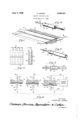
- FIG. 1 is a perspective view of a contact carrier strip of the present invention having female contacts secured therein;
- FIG. 2 is a perspective view of one of the female contacts of FIG. 1;
- FIG. 3 is a sectional view taken along the lines 33 of FIG. 1;
- FIG. 4 is a perspective View of a male contact which can be secured Within a carrier strip in the manner of FIG. 1;
- FIG. 5 is a plan view of the carrier strip of FIG. 1 with portions broken away for the sake of clarity;
- FIG. 6 is a sequential view illustrating the welding of a contact of the carrier strip of FIG. 1 to a conductor of a ribbon cable.
- the carrier strip 10 basically comprises thermoplastic holding portion '12 from which female contacts 14 extend.
- the contact carrier strip is preferably formed simultaneously or integrally so that the contacts 14 are embedded in the holding strip 12 upon discharge from the molding area. It is conceivable that other manufacturing techniques may be employed, such as separately forming the holding strip, heating the contacts and inserting the heating contacts under pressure so that they penetrate within the holding strip 12.
- a typical female contact 14 is shown in perspective in FIG. 2 and a typical male contact 16 is shown in FIG. 4.
- the female and male contacts 14 and 16 indicated here illustrate the operation of the present invention.
- the present invention is in no way limited to the precise structure of the female and male contacts described herein. It will be readily apparent to those skilled in the art that contacts, both male and female or hermaphroditic may be utilized.
- the female and male contacts 14 and 16 of FIGS. 2 and 4 are constructed generally along the lines of certain contacts disclosed and claimed in co-pending application Ser. No. 501,407, filed Oct. 22, 1965, entitled Cylindrical Connector Contact (inventorHerbert E. Ruehlemann), and the disclosure of said patent application is hereby incorporated in reference.
- the female contact 14 basically comprises a cylindrical mating section 18 and a relatively flat or uniplanar tail section 20.
- the contact 14 further includes cylindrical shoulder 22 from which the tail section 20 extends.
- a recess 24 is provided which separates shoulder 22 from mating section 18.
- the tail section 20 includes convex points 26 which strengthen the connection between the contacts 14 and the holding strip 12.
- FIG. 3 The disposition of the contacts 14 in the holding strip 12 is illustrated in FIG. 3 which indicates that the entire tail section 20, together with shoulder 22 and recess 24 is completely incapsulated within the holding strip 12 which terminates forwardly in edge 28 along a portion of the length of mating section 18. It will readily occur to those skilled in the art that the actual width of the holding strip 12 may be narrowed or may be broader, depending upon the needs of a particular situation.
- the holding strip 12 will encompass only middle portions of the contacts, thereby leaving substantial portions of the mating section and the tail section exposed.
- the holding strip 12 does have a protective function, since it prevents oxidation of the tail section 20 as well as lending some mechanical support.
- the female contact further includes a central bore 30 which is adapted to receive the spring member 32 of the male contact 16, the details of which are shown in FIG. 4.
- the male contact 16 as well as the female contact 14 may be both comprised of maximum hardness beryllium copper, although softer materials may be used, depending upon the needs of a particular situation.
- the male contact 16 basically comprises in addition to spring member 32 a body section 34 and cylindrical shoulder 36 from which tail section 38 extends.
- a recess 40 is provided which separates shoulder 36 from body setction 34.
- the tail section 38 includes convex points 42 which strengthen the connection between the contacts 16 and the holding strip 12.
- the disposition of the contacts 16 in a holding strip is substantially identical to the FIGS. 1 and 3 disposition of female contacts 14 in the holding strip 12.
- the entire tail section 38, together with shoulder 36 and recess 40 may be completely incapsulated within the holding strip 12 that will terminate in a manner substantially identical to the showing of FIG. 3.
- the actual width of the holding strip 12 in conjunction with either female contacts 14 or male contacts 16 may be narrowed or may be broader depending upon the needs of a particular situation.
- the contact carrier strip of the present invention facilitates the handling of a plurality of female contacts 14 or male contacts 1 6. It is preferred that the female contacts or male contacts be integrally molded within the holding strip 12 at the time of the formation of the holding strip 12 as previously described. At times, it may be desirable to initially heat the contacts and then force them into a thermoplastic holding strip as described in Ruehlemann Patent No. 3,182,276.
- a ribbon cable is basically an elongated strip of plastic having conductive wires or members embedded or printed therein.
- the insulation of the ribbon cable should be thermoplastic or exhibit thermoplastic characteristics in the manner of a vinyl plastic or polyethylene.
- a ribbon cable as known in the art is extremely thin and possesses a series of parallel conductive members which run lengthwise of the ribbon cable.
- the term ribbon cable is broad enough to include intersecting conductors or conductive matrices.
- the ribbon cable 44 comprises thermoplastic insulation 46 and at least one embedded conductor 48.
- the tail 20 of a female terminal as embedded in holding strip 12 is placed closely above the ribbon cable 44 in such a manner that the tail 20 is superimposed upon the conductor 40.
- electrically heated electrodes 50 and 52 are employed in conjunction with current source 54 and leads 56 and 58.
- a condenser discharge circuit (not shown) as described in said application Ser. No. 317,617 may also be utilized in a switch or timer arrangement.
- FIG. 6A pressure is applied to the hot electrodes in the direction of the respective arrows in order to urge the hot electrodes 50 and 52 toward each other.
- the ribbon cable adjacent hot electrode 52 will immediately flow into a bulge 60.
- the insulation adjacent electrode 50 is melted away as shown in FIG. 6-B.
- FIG. 6-C Under continued heat and pressure as shown in FIG. 6-C, the insulation is flowed away not only from the top surface of contact tail 20, but also the heat passing from electrode 50 through tail section 20 as well as the heat emitted by lower electrode 52 passes through the ribbon cable and melts away the insulation adjacent the lower face of the tail 20.
- the holding strip 12 may be desirable to form from a thermoplastic material that will melt at a lower temperature than the thermoplastic material of the ribbon cable 44. In this way, the holding strip insulation will be more quickly flowed away than the ribbon cable insulation. Thus, the tail 20 will be rather quickly exposed to top electrode 50.
- the contact carrier strip of the present invention not only facilitates the handling of contacts, but is also well suited to expedite the holding of contacts to the conductors of a ribbon cable.
- the present invention is also well suited where the contacts are of small size.
- a protective insulation coating or layer may be applied about the welded area for insulating as well as protective purposes.
- a contact carrier strip comprising an elongated, relatively thin thermoplastic strip having a narrow edge; and a plurality of contacts secured in said strip in precise relationship to each other; said contacts including a mating section and a tail section, the mating sections of the contacts projecting beyond said narrow edge of the thermoplastic strip, and the tail sections of the contacts being encapsulated within said narrow edge by said thermoplastic strip whereby the tail sections of the contacts are protected by upper and lower thin thermoplastic layers.
- tail sections include convex points which strengthen the connection between'the thermoplastic strip and the tail sections.
- thermoplastic strip 5.
- said ribbon being relatively flat and having a plurality of spaced conductors encapsulated side-by-side in thermoplastic insulation
- said contact carrier strip comprising an elongated, relatively thin thermoplastic strip having a narrow edge, and having a plurality of contacts secured therein with a spacing matching that of said conductors; each contact having a mating section extending beyond said thermoplastic strip and a tail secion initially encapsulated by said thermoplastic strip and being welded to a different one of the plurality of conductors within the insulation of said ribbon cable, and portions of said thermoplastic strip being removed to achieve actual contact between the tail section of a contact and a conductor in said ribbon cable.
- tail section includes convex points which strengthen the connection between the thermoplastic strip and the tail section.
Landscapes
- Engineering & Computer Science (AREA)
- Manufacturing & Machinery (AREA)
- Coupling Device And Connection With Printed Circuit (AREA)
- Connector Housings Or Holding Contact Members (AREA)
- Multi-Conductor Connections (AREA)
Applications Claiming Priority (1)
| Application Number | Priority Date | Filing Date | Title |
|---|---|---|---|
| US53537966A | 1966-03-17 | 1966-03-17 |
Publications (1)
| Publication Number | Publication Date |
|---|---|
| US3448431A true US3448431A (en) | 1969-06-03 |
Family
ID=24133918
Family Applications (1)
| Application Number | Title | Priority Date | Filing Date |
|---|---|---|---|
| US535379A Expired - Lifetime US3448431A (en) | 1966-03-17 | 1966-03-17 | Contact carrier strip |
Country Status (5)
| Country | Link |
|---|---|
| US (1) | US3448431A (da) |
| DE (1) | DE1640023A1 (da) |
| DK (1) | DK124848B (da) |
| FR (1) | FR1514808A (da) |
| GB (1) | GB1139244A (da) |
Cited By (9)
| Publication number | Priority date | Publication date | Assignee | Title |
|---|---|---|---|---|
| US3673681A (en) * | 1969-04-01 | 1972-07-04 | Inforex | Electrical circuit board wiring |
| US3675320A (en) * | 1967-09-02 | 1972-07-11 | Kawai Gakki Susakusho Kk | Electric contact member |
| US3678437A (en) * | 1970-12-30 | 1972-07-18 | Itt | Flat cable wafer |
| US3778883A (en) * | 1972-06-02 | 1973-12-18 | Honeywell Inf Systems | Process of mass soldering electrical components to circuit boards having runs formed from insulated magnet wire |
| US3812581A (en) * | 1969-11-24 | 1974-05-28 | Wells Electronics | Method for forming electrical joints between intermediate parts of an elongated conductor and selected conductive elements on an electrical assembly |
| US5045641A (en) * | 1989-01-26 | 1991-09-03 | Sankyo Kasei Co., Ltd. | Moulded electrical connector and method for manufacturing same |
| EP0651463A3 (en) * | 1993-10-28 | 1996-10-16 | Nec Corp | Method for soldering an electrical cable to a circuit board. |
| US5575681A (en) * | 1994-12-16 | 1996-11-19 | Itt Corporation | Connector termination to flat cable |
| WO2006042783A1 (de) * | 2004-10-18 | 2006-04-27 | Siemens Aktiengesellschaft | Kontaktierung eines kabels an einer flexiblen leiterbahn |
Families Citing this family (1)
| Publication number | Priority date | Publication date | Assignee | Title |
|---|---|---|---|---|
| FR2527857A1 (fr) * | 1982-05-27 | 1983-12-02 | Electro Hydraulique Seh | Moteur electrique a stator bobine et son procede de fabrication |
Citations (6)
| Publication number | Priority date | Publication date | Assignee | Title |
|---|---|---|---|---|
| US3016512A (en) * | 1959-09-22 | 1962-01-09 | Bell Telephone Labor Inc | Connector assembly |
| US3022481A (en) * | 1960-02-26 | 1962-02-20 | Stepoway Theodore | Electrical connector |
| US3129995A (en) * | 1960-11-14 | 1964-04-21 | Hi Shear Corp | Electrical connector |
| US3155809A (en) * | 1964-04-21 | 1964-11-03 | Digital Sensors Inc | Means and techniques for making electrical connections |
| US3156514A (en) * | 1961-11-21 | 1964-11-10 | Hi Shear Corp | Connector |
| US3206717A (en) * | 1962-06-12 | 1965-09-14 | Amp Inc | Connector assembly |
-
1966
- 1966-03-17 US US535379A patent/US3448431A/en not_active Expired - Lifetime
-
1967
- 1967-03-14 GB GB11873/67A patent/GB1139244A/en not_active Expired
- 1967-03-15 DE DE19671640023 patent/DE1640023A1/de active Pending
- 1967-03-16 DK DK137367AA patent/DK124848B/da unknown
- 1967-03-17 FR FR99240A patent/FR1514808A/fr not_active Expired
Patent Citations (6)
| Publication number | Priority date | Publication date | Assignee | Title |
|---|---|---|---|---|
| US3016512A (en) * | 1959-09-22 | 1962-01-09 | Bell Telephone Labor Inc | Connector assembly |
| US3022481A (en) * | 1960-02-26 | 1962-02-20 | Stepoway Theodore | Electrical connector |
| US3129995A (en) * | 1960-11-14 | 1964-04-21 | Hi Shear Corp | Electrical connector |
| US3156514A (en) * | 1961-11-21 | 1964-11-10 | Hi Shear Corp | Connector |
| US3206717A (en) * | 1962-06-12 | 1965-09-14 | Amp Inc | Connector assembly |
| US3155809A (en) * | 1964-04-21 | 1964-11-03 | Digital Sensors Inc | Means and techniques for making electrical connections |
Cited By (10)
| Publication number | Priority date | Publication date | Assignee | Title |
|---|---|---|---|---|
| US3675320A (en) * | 1967-09-02 | 1972-07-11 | Kawai Gakki Susakusho Kk | Electric contact member |
| US3673681A (en) * | 1969-04-01 | 1972-07-04 | Inforex | Electrical circuit board wiring |
| US3812581A (en) * | 1969-11-24 | 1974-05-28 | Wells Electronics | Method for forming electrical joints between intermediate parts of an elongated conductor and selected conductive elements on an electrical assembly |
| US3678437A (en) * | 1970-12-30 | 1972-07-18 | Itt | Flat cable wafer |
| US3778883A (en) * | 1972-06-02 | 1973-12-18 | Honeywell Inf Systems | Process of mass soldering electrical components to circuit boards having runs formed from insulated magnet wire |
| US5045641A (en) * | 1989-01-26 | 1991-09-03 | Sankyo Kasei Co., Ltd. | Moulded electrical connector and method for manufacturing same |
| EP0651463A3 (en) * | 1993-10-28 | 1996-10-16 | Nec Corp | Method for soldering an electrical cable to a circuit board. |
| US5575681A (en) * | 1994-12-16 | 1996-11-19 | Itt Corporation | Connector termination to flat cable |
| WO2006042783A1 (de) * | 2004-10-18 | 2006-04-27 | Siemens Aktiengesellschaft | Kontaktierung eines kabels an einer flexiblen leiterbahn |
| US20090053943A1 (en) * | 2004-10-18 | 2009-02-26 | Siemens Aktiengesellschaft | Bringing a cable into contact with a flexible strip conductor |
Also Published As
| Publication number | Publication date |
|---|---|
| GB1139244A (en) | 1969-01-08 |
| FR1514808A (fr) | 1968-02-23 |
| DK124848B (da) | 1972-11-27 |
| DE1640023A1 (de) | 1970-08-06 |
Similar Documents
| Publication | Publication Date | Title |
|---|---|---|
| US3605060A (en) | Apparatus for terminating electrical ribbon cable | |
| US3155809A (en) | Means and techniques for making electrical connections | |
| US3737833A (en) | Ribbon cable connector system having feed thru connector | |
| US3697925A (en) | Termination means for flat cable | |
| US3573719A (en) | Connector for multiple-conductor cable | |
| US3860318A (en) | Pre-loaded electrical connector | |
| US3862792A (en) | Electrical connector assembly | |
| US3587028A (en) | Coaxial connector guide and grounding structure | |
| US3093434A (en) | Molded plug | |
| US3448431A (en) | Contact carrier strip | |
| US3675180A (en) | Flat cable connector | |
| US3835442A (en) | Termination module utilizing conductive elastomer bussing | |
| ES415827A1 (es) | Perfeccionamientos en la construccion de conectores elec- tricos. | |
| GB1350540A (en) | Flexible flat cable and electrical assemblies | |
| US3618207A (en) | Method of manufacturing strip connectors | |
| KR850005031A (ko) | 임피이던스 제어장치를 가진 가요성 회로를 이용한 전기 접속기 | |
| ES264802U (es) | Dispositivo para conectar alambres aislados a elementos de conexion de contacto doble. | |
| US3585570A (en) | Electrical terminal assembly | |
| EP0261905A2 (en) | An electrical connector and a method for connecting wires thereto | |
| US5580271A (en) | SCSI cable with termination circuit and method of making | |
| US4029377A (en) | Push-on bus bar | |
| KR900011081A (ko) | 전기 콘넥터의 종단접속법 | |
| ES8703673A1 (es) | Un metodo para dotar de terminales a un conductor electrico aislado. | |
| US3654594A (en) | Crimp type terminal | |
| US3900241A (en) | Wiring harness |