US3461691A - Multifeed circular knitting machines - Google Patents
Multifeed circular knitting machines Download PDFInfo
- Publication number
- US3461691A US3461691A US553135A US3461691DA US3461691A US 3461691 A US3461691 A US 3461691A US 553135 A US553135 A US 553135A US 3461691D A US3461691D A US 3461691DA US 3461691 A US3461691 A US 3461691A
- Authority
- US
- United States
- Prior art keywords
- yarn
- machine
- stand
- creel
- bobbin
- Prior art date
- Legal status (The legal status is an assumption and is not a legal conclusion. Google has not performed a legal analysis and makes no representation as to the accuracy of the status listed.)
- Expired - Lifetime
Links
- 238000009940 knitting Methods 0.000 title description 33
- 230000005856 abnormality Effects 0.000 description 15
- 239000004744 fabric Substances 0.000 description 4
- 210000003128 head Anatomy 0.000 description 3
- 235000004443 Ricinus communis Nutrition 0.000 description 1
- 240000000528 Ricinus communis Species 0.000 description 1
- 229910000831 Steel Inorganic materials 0.000 description 1
- 230000002159 abnormal effect Effects 0.000 description 1
- 239000000919 ceramic Substances 0.000 description 1
- 239000002131 composite material Substances 0.000 description 1
- 238000010276 construction Methods 0.000 description 1
- 230000001627 detrimental effect Effects 0.000 description 1
- 230000000694 effects Effects 0.000 description 1
- 230000014759 maintenance of location Effects 0.000 description 1
- 238000000034 method Methods 0.000 description 1
- 238000012986 modification Methods 0.000 description 1
- 230000004048 modification Effects 0.000 description 1
- 238000004806 packaging method and process Methods 0.000 description 1
- 229920000915 polyvinyl chloride Polymers 0.000 description 1
- 239000004800 polyvinyl chloride Substances 0.000 description 1
- 230000000284 resting effect Effects 0.000 description 1
- 239000010959 steel Substances 0.000 description 1
Images




Classifications
-
- D—TEXTILES; PAPER
- D04—BRAIDING; LACE-MAKING; KNITTING; TRIMMINGS; NON-WOVEN FABRICS
- D04B—KNITTING
- D04B15/00—Details of, or auxiliary devices incorporated in, weft knitting machines, restricted to machines of this kind
- D04B15/38—Devices for supplying, feeding, or guiding threads to needles
- D04B15/40—Holders or supports for thread packages
- D04B15/42—Frames for assemblies of two or more reels
Definitions
- This invention appertains to a multifeed circular knitting machine for producing tubular fabric and has reference to such a machine equipped with a comparatively large number of feeds and of the class adapted for use in conjunction with at least one portable bobbin stand or creel set up next to the machine.
- Such a bobbin stand or creel which may, if desired, be furnished with castors, is set up on the floor adjacent to the machine and comprises a structure of longitudinals and ends fitted with upstanding pegs and associated holders for cones or other appropriate yarn packages.
- the present invention finds a useful application in conjunction with a multifeed circular knitting machine having a large open top cylinder and suitable for producing tubular fabric which is ultimately destined to be coated with polyvinyl chloride.
- a multifeed circular knitting machine having a large open top cylinder and suitable for producing tubular fabric which is ultimately destined to be coated with polyvinyl chloride.
- Such a machine may be equipped with as many as ninety-six feeds.
- the invention is also applicable to large multifeed interlock and outerwear machines.
- a multifeed circular knitting machine of the class concerned has had mounted above its knitting head a comparatively high superstructure carrying yarn guides, knot catchers and a top series of yarn failure or/ and abnormality detector devices incorporated in electrical stop motion circuitry.
- Such a superstructure necessitates a complicated threading up system in which the single yarn ends extending across to the machine from relevant yarn packages mounted on the bobbin stand or creel have been required to extend upwardly to points high up on the superstructure before extending down again to needles in the cylinder.
- the primary object of the present invention is to provide an improved arrangement of a circular multifeed knitting machine of the class herein referred to associated with a bobbin stand or creel, the arrangement being designed to obviate the foregoing disadvantages as will be hereinafter described.
- the aforesaid superstructure of the knitting machine is removed, and at least one of the series of yarn failure or/and abnormality detector devices together with relevant yarn guides are mounted upon the independent and portable bobbin stand or creel.
- the expression yarn failure is used in a generic sense and intended to include the sudden absence of a travelling yarn or thread and as, for instance, when a yarn or thread either breaks or runs out.
- the expression yarn abnormality this is intended to cover not only excessive yarn or thread tension but also any other abnormal running yarn condition likely to result either in ditficulty in knitting or damage to the fabric produced.
- the composite expression yarn failure or/ and abnormality detector device means any device designed to detect and signal to electric stop motion circuitry any appropriate one or more of the foregoing yarn or thread conditions.
- the series of yarn failure or/and abnormality detector devices previously provided at the top of a superstructure on the circular multifeed knitting machine are now mounted upon the top of the portable bobbin stand or creel, whereas the remaining detector devices included in the arrangement are mounted upon a carrier component in turn supported on the said knitting machine at a lower level only a comparatively small vertical distance above the top of the needle cylinder.
- More than one such independent and portable bobbin stand or creel may be arranged adjacent to one and the same multifeed circular knitting machine.
- Each stand or creel may be straight from end to end, or it may be of an arcuate shape and thus comprise curved tubular steel longitudinals and radially extending ends.
- FIGURE 1 is an elevational view of a portion of a typical multifeed circular knitting machine shown adjacent a bobbin stand or creel (one end only of which can be seen), the figure showing the path of a travelling yarn as it extends upwardly from the relevant cone or bobbins, through detector devices mounted respectively on the stand or creel and the machine and finally down to the needles,
- FIGURE 2 is a detail plan view as seen in the direction of the arrow A in FIGURE 1,
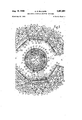
- FIGURE 3 is a plan view illustrating a typical layout of a plurality of bobbin stands or creels suitably arranged around a large multifeed circular knitting machine having a relatively great number of feeds,
- FIGURE 4 is a plan view relating to a multifeed circular knitting machine which has a less number of feeds and is operated in conjunction with two straight bobbin stands or creels,
- FIGURE 5 is a plan view illustrating in greater detail one of the series of yarn failure or/ and abnormality detector devices mounted on each of the bobbin stands or creels,
- FIGURE 6 similarly illustrates in detail one of the series of yarn failure or/ and abnormality detector devices mounted upon support elements in turn supported upon the circular knitting machine,
- FIGURE 7 is a detail view of one of the yarn feed Wheels mounted on the knitting machine
- FIGURE 8 is a perspective view of a modified form of portable bobbin stand or creel adapted to be readily dismantled
- FIGURE 9 is a view of such a stand showing the dismantling procedure
- FIGURE is a detail perspective view depicting a modification.
- FIGURES 1 and 3 depict many components and features in common, so far as the portrayal of the invention is concerned, it is to be clearly understood that the actual machine and the bobbin stands or creels are not of identical forms in the two figures.
- the creels shown in FIGURE 3 are longitudinally curved and each carry a larger number of bobbins or cones than the creel of FIGURE 1 which is straight.
- the bobbins or cones at the lower part of the creels are mounted with the axes thereof vertical, whereas only the rear most bobbins or cones on the creel of FIGURE 1 are vertical. The result of this arrangement is that the yarn guides in the two creels are arranged in different positions.
- FIGURE 1 a large open top rotary needle cylinder of the multifeed circular knitting machine is provided within a sinker ring 2.
- the cylinder gear housed within a casing 3, is adapted to be driven from a horizontal main shaft at 4 through the medium of gearing not shown but encased at 5.
- the entire knitting head of the machine is supported from the framework 6.
- FIGURE 1 Although the illustrated machines are equipped with large numbers of feeds, a yarn feeder 7 at only one of such feeds is shown in FIGURE 1.
- the reference numeral 8 indicates the cross arms of the horrle bobbin stand of the machine.
- each portable stand or creel comprises a structure of parallel longitudinals 10 and straight, radially extending ends 11 adapted to provide legs such as 12 (FIGURE 1). The structure is fitted with upstanding pegs such as 13 and associated holders 14 for yarn packages in the form of cones C.
- the multifeed circular knitting machine is not provided with a superstructure supported by or from the cross arms 8, and one series of yarn failure or/and abnormality detector devices 15 (i.e., those previously provided at the top of such a superstructure), together with associated yarn guides 16 and 17, are all mounted upon the one or more independent and portable bobbin stands or creels 9.
- the remaining detector devices 18 included in the arrangement are mounted upon a common carrier ring 19 in turn supported from the cross arms 8 of the machine in a manner presently to be described.
- Each of the detector devices 15 is of the kind comprising, as shown in FIGURE 5, a pair of spaced pivoted dropper hooks 20 and a movable excessive tension plate 21.
- the excessive tension plate 21 is mounted on a U- shaped section of wire 21a pivoted at the ends thereof to the main body 15a of the detector device 15.
- a pair of ceramic sleeves C are mounted on the arms of Wire section 21a and the yarn Y runs over sleeves C and over plate 21, the dropper books 20 resting on the travelling yarn Y.
- the U-shaped section of wire 21a is spring urged upwardly so that the yarn Y rides thereon, against the spring biasing.
- the ends of carrier wire 21a and the inner ends of the dropper hooks 20 influence a switch mechanism located within body 15a, the switch mechanism being incorporated in an electrical stop motion circuit.
- a travelling yarn Y threaded through each detector device 15 holds up the dropper hooks and passes over the excessive tension plate 21 so that, in the event of the yarn breaking or running out, the dropper hooks 20 fall, whereas the excessive tension plate 21 is pulled down in the event of the yarn becoming unduly tensioned, the result in either case being to make the electrical stop motion circuit.
- the detector devices 15 on the or each bobbin stand or creel 9 may also be furnished with signal lamps adapted, when lighted, to indicate the source of yarn failure or yarn abnormality.
- the detector devices 18 on the multifeed circular knitting machine are each of the known type comprising, as illustrated in FIGURES 1 and '6, a spring-influenced pivoted arm 22 which at its outer end 22a is formed for the retention and guidance of a travelling yarn Y running over it and at its other end is associated with an electrical switch or switch contacts 23 incorporated in a stop motion circuit.
- the arrangement of each detector device 18 is such that while a yarn Y is running normally over the pivoted arm 22 the latter is held down to maintain the relevant stop motion circuit open. Whenever the yarn becomes excessively tensioned the arm is pulled down to the point where the yarn slips Oh it and the released arm thereupon swings up to make the circuit and initiate stoppage of the machine.
- each of these detector devices 18 may, if desired and like the devices 15, have combined therewith a signal lamp which is so incorporated into the circuit that it lights up to indicate a yarn failure or development of a yarn abnormality at that detector.
- the common carrier ring 19 is itself carried by pillars or similar vertical elements such as 24 (FIGURE 1) which are secured upon circumferentially spaced radially extending horizontal rods 25.
- the inner end of each rod 25 is secured in a bored bracket 26 mounted up on a further ring 27.
- this ring 27 is provided with lugs 27a whereby it is secured to, and thus carried by, the outer ends of the cross arms 8.
- a support 28 for a circular series of fixed pot eyes 29one to each feed is located below these cross arms, and just above the rotary knitting portion of the machine.
- each yarn feeding device 35 is also mounted upon each radial rod 25, between the vertical element 24 thereon and the lug 30a, the lower ends of these brackets carrying a ring 33 in turn serving to support rotary tape wheels 34 of yarn feeding devices 35 of known tapeoperated type.
- rotary tape wheels 34 of yarn feeding devices 35 of known tapeoperated type.
- FIGURE 1 there are two coaxial tape wheels 34 per device 35, and in the layout depicted in FIGURE 3 there are forty-eight of the devices 35, and hence ninety-six of the wheels 34, one to each feed.
- Each yarn feeding device includes a plate 36 in which are set two pot eye guides 37.
- a continuous tape 51 extends around the machine in contact with the peripheries of each of the upper tape wheels 34 in each device 35.
- a similar tape (not shown) extends around each of the lower wheels 34 in the devices.
- These tapes each pass around a drive pulley 52 at a location on the periphery of the machine, the two pulleys 52 being mounted coaxially on a vertical drive shaft 54 driven from the gearbox of the machine.
- the tape wheels are all driven in rotation from pulleys 52.
- Yarn to be fed by a tape wheel 34 is passed around the periphery of the latter between the surface of the wheel and the tape.
- each independent and portable bobbin stand or creel 9 includes a horizontal rail 38 upon which are mounted the aforementioned yarn failure or/and abnor mality detector devices 15.
- the rail 38 is disposed at a height a little above that of the radial rods 25 and hence also that of the ring 30 in which are fitted the pot eyes 31.
- a little below and in advance of the rail 38 there is provided on each stand or creel another horizontal rail 39 in which the yarn guides 17, also in the form of pot eyes, are fitted.
- the rail 39 is carried by arms 40 secured to upright portions 41 of the stand or creel 9.
- the yarn guides 16 are formed at the outer ends of horizontal wires or arms 42 secured upon the one or more bobbin stands or creels.
- the latter extends first upwardly from the relevant cone or bobbin C, through at least one of the guides 16 and from thence up to and through a detector device 15 mounted upon the rail 38 of the bobbin stand or creel 9. From this detector device 15 the yarn Y extends downwardly and through the appropriate guide 17 set in the rail 39 on the stand or creel, whereafter it extends horizontally or nearly so right across the gap between the stand or creel and the knitting machine.
- the yarn passes down through the relevant pot eye guide 31 mounted in the ring 30, through a pot eye guide 37 in a plate 36, then round a circumferential groove in the relevant tape wheel 34, next over the pivoted arm 22 of a detector device 18 on the machine and finally down through a pot eye 29 to the needles.
- the invention includes, as a feature, and for use in conjunction with a knitting machine, an independent portable bobbin stand or creel furnished with a set of yarn failure or/ and abnormality detector devices.
- creels for 192 bobbins may be arranged for pig-tail tie up. In this case about a 4 ton of yarn, calculated at 3 pounds a cone, would be involved. As will be appreciated to lift a load of this size a height of 6 feet in a conventional machine with an overhead bobbin-stand creates considerable difficulty which has been solved by the present invention.
- FIGURE 4 illustrates in plan view, a 48-feed circular knitting machine which is operated in conjunction with two straight bobbin stands or creels 9
- FIG- URES 8 and 9 Such a collapsible stand or creel is illustrated in FIG- URES 8 and 9, the article' being complete in FIGURE 8 and shown in the course of dismantling in FIGURE 9.
- the modified bobbin stand or creel is based on the fact that the ends 11 can be separated from the parallel tubular longitudinals 10 and the upright portions 41 can be similarly separated both from the said ends 11 and also from a horizontal rail 43, by the simple expedient of loosening screws.
- the inner sides of the ends 11 have welded thereto sockets 44 to receive the ends of the tubular longitudinals 10 each joint being secured by two screws 45.
- Similar sockets 46 combined with screws 45 are provided on the top rails of the ends 11 to receive the lower ends of the uprights 41
- sockets 47 welded to these uprights serve to receive the ends of the horizontal rail 43.
- Screw and nut fastenings at 48, 49 are provided to secure in position the rails 38 and 39
- the sockets may alternatively be formed as shown at 44 in FIGURE 10, the lugs 44a being adapted to be secured together by a single screw 50.
- a circular multifeed knitting machine equipped with needles and having no superstructure; at least one independent portable bobbin stand set up next to said machine for supporting bobbins of yarn; a first series of yarn failure and abnormality detector devices mounted upon the top of the said stand; an admirwhile bobbin stand mounted on the machine, a first ring secured to said bobbin stand, brackets mounted on said first ring, horizontal rods extending radially outwardly from said brackets, a second ring supported from said horizontal rods, and a second series of detector devices mounted upon said second ring, and yarn guides located on both the machine and the stand for guiding and threading yarns travelling from the bobbins to the needles of the machine through the detector devices of both series.
- a combination according to claim 1 further comprising yarn feeding devices including wheels, a ring for supporting said wheels, and brackets depending from said horizontal rods for carrying said ring.
- a combination according to claim 2 further comprising a ring for mounting the yarn guides on the machine, said ring being supported by said horizontal rods.
- a combination according to claim 3 further comprising a horizontal rail mounted on the top of the portable bobbin stand for mounting the relevant detector devices, said rail being disposed at a height a short distance above said ring for mounting said yarn guides, said combination further comprising a further horizontal rail mounted below and in advance of said first-mentioned rail on said stand, and yarn guiding eyes fitted in said further horizontal rail.
Landscapes
- Engineering & Computer Science (AREA)
- Textile Engineering (AREA)
- Knitting Machines (AREA)
Applications Claiming Priority (1)
| Application Number | Priority Date | Filing Date | Title |
|---|---|---|---|
| GB23862/65A GB1092064A (en) | 1965-06-04 | 1965-06-04 | Improvements relating to multi-feed circular knitting machines |
Publications (1)
| Publication Number | Publication Date |
|---|---|
| US3461691A true US3461691A (en) | 1969-08-19 |
Family
ID=10202531
Family Applications (1)
| Application Number | Title | Priority Date | Filing Date |
|---|---|---|---|
| US553135A Expired - Lifetime US3461691A (en) | 1965-06-04 | 1966-05-26 | Multifeed circular knitting machines |
Country Status (3)
| Country | Link |
|---|---|
| US (1) | US3461691A (fr) |
| FR (1) | FR1500007A (fr) |
| GB (1) | GB1092064A (fr) |
Cited By (12)
| Publication number | Priority date | Publication date | Assignee | Title |
|---|---|---|---|---|
| US3596851A (en) * | 1968-06-24 | 1971-08-03 | Santoni & Spa | Bobbin-carrier for circular knitting machines |
| US3669379A (en) * | 1970-05-18 | 1972-06-13 | Morris Philip | Yarn stand |
| US3678713A (en) * | 1969-07-29 | 1972-07-25 | Inst Textile Tech | Creel structure for circular knitting machines |
| US3762185A (en) * | 1970-03-17 | 1973-10-02 | Morat Gmbh Franz | Bobbin crafting and thread feeding device for circular knitting machines |
| US3777512A (en) * | 1972-03-31 | 1973-12-11 | Burlington Industries Inc | Creel assembly including stop motion devices for circular knitting machines |
| US3858827A (en) * | 1972-02-14 | 1975-01-07 | Allan Glassbrook | Creel |
| US3975926A (en) * | 1975-02-24 | 1976-08-24 | Riccardo Tenconi | Feed device for circular knitting machines of the type manufacturing open fabric |
| US4043154A (en) * | 1974-08-07 | 1977-08-23 | Wilh. Bleyle Kg | Spool rack |
| US4735066A (en) * | 1986-10-10 | 1988-04-05 | H. Stoll Gmbh & Co. | Flat knitting machine with bobbin holders |
| US6237866B1 (en) * | 1998-02-17 | 2001-05-29 | Yagikuma & Co., Ltd. | Yarn unwinding tension stabilizer and a yarn unwinding tension stabilizing apparatus for a warping creel using the same |
| CN102899797A (zh) * | 2012-09-12 | 2013-01-30 | 冯加林 | 一种引塔夏横编织机的引线方法及引线装置 |
| CN108035060A (zh) * | 2018-01-31 | 2018-05-15 | 海盐宏丰针织有限公司 | 一种针织圆机的导纱架 |
Citations (6)
| Publication number | Priority date | Publication date | Assignee | Title |
|---|---|---|---|---|
| US932522A (en) * | 1905-06-23 | 1909-08-31 | Simon W Wardwell | Creel. |
| US1022283A (en) * | 1905-03-22 | 1912-04-02 | Universal Winding Co | Creel. |
| US2387100A (en) * | 1944-03-27 | 1945-10-16 | Wachsman Michael | Electric distributor ring for rotary knitting machines |
| US2967413A (en) * | 1957-12-23 | 1961-01-10 | Mellar Bromley & Co Ltd | Yarn feeding and controlling means for knitting machines |
| US3018645A (en) * | 1959-07-06 | 1962-01-30 | Fried Benjamin | Yarn storage and feeding system for circular knitting machines |
| DE1172006B (de) * | 1960-11-19 | 1964-06-11 | Isco Wirkwarenfabrik | Garnzufuehrung an Rundwirk- und -strickmaschinen |
-
1965
- 1965-06-04 GB GB23862/65A patent/GB1092064A/en not_active Expired
-
1966
- 1966-05-26 US US553135A patent/US3461691A/en not_active Expired - Lifetime
- 1966-06-03 FR FR64141A patent/FR1500007A/fr not_active Expired
Patent Citations (6)
| Publication number | Priority date | Publication date | Assignee | Title |
|---|---|---|---|---|
| US1022283A (en) * | 1905-03-22 | 1912-04-02 | Universal Winding Co | Creel. |
| US932522A (en) * | 1905-06-23 | 1909-08-31 | Simon W Wardwell | Creel. |
| US2387100A (en) * | 1944-03-27 | 1945-10-16 | Wachsman Michael | Electric distributor ring for rotary knitting machines |
| US2967413A (en) * | 1957-12-23 | 1961-01-10 | Mellar Bromley & Co Ltd | Yarn feeding and controlling means for knitting machines |
| US3018645A (en) * | 1959-07-06 | 1962-01-30 | Fried Benjamin | Yarn storage and feeding system for circular knitting machines |
| DE1172006B (de) * | 1960-11-19 | 1964-06-11 | Isco Wirkwarenfabrik | Garnzufuehrung an Rundwirk- und -strickmaschinen |
Cited By (13)
| Publication number | Priority date | Publication date | Assignee | Title |
|---|---|---|---|---|
| US3596851A (en) * | 1968-06-24 | 1971-08-03 | Santoni & Spa | Bobbin-carrier for circular knitting machines |
| US3678713A (en) * | 1969-07-29 | 1972-07-25 | Inst Textile Tech | Creel structure for circular knitting machines |
| US3762185A (en) * | 1970-03-17 | 1973-10-02 | Morat Gmbh Franz | Bobbin crafting and thread feeding device for circular knitting machines |
| US3669379A (en) * | 1970-05-18 | 1972-06-13 | Morris Philip | Yarn stand |
| US3858827A (en) * | 1972-02-14 | 1975-01-07 | Allan Glassbrook | Creel |
| US3777512A (en) * | 1972-03-31 | 1973-12-11 | Burlington Industries Inc | Creel assembly including stop motion devices for circular knitting machines |
| US4043154A (en) * | 1974-08-07 | 1977-08-23 | Wilh. Bleyle Kg | Spool rack |
| US3975926A (en) * | 1975-02-24 | 1976-08-24 | Riccardo Tenconi | Feed device for circular knitting machines of the type manufacturing open fabric |
| US4735066A (en) * | 1986-10-10 | 1988-04-05 | H. Stoll Gmbh & Co. | Flat knitting machine with bobbin holders |
| US6237866B1 (en) * | 1998-02-17 | 2001-05-29 | Yagikuma & Co., Ltd. | Yarn unwinding tension stabilizer and a yarn unwinding tension stabilizing apparatus for a warping creel using the same |
| CN102899797A (zh) * | 2012-09-12 | 2013-01-30 | 冯加林 | 一种引塔夏横编织机的引线方法及引线装置 |
| CN102899797B (zh) * | 2012-09-12 | 2014-05-28 | 冯加林 | 一种引塔夏横编织机的引线方法及引线装置 |
| CN108035060A (zh) * | 2018-01-31 | 2018-05-15 | 海盐宏丰针织有限公司 | 一种针织圆机的导纱架 |
Also Published As
| Publication number | Publication date |
|---|---|
| FR1500007A (fr) | 1967-11-03 |
| GB1092064A (en) | 1967-11-22 |
Similar Documents
| Publication | Publication Date | Title |
|---|---|---|
| US3461691A (en) | Multifeed circular knitting machines | |
| CN108103651A (zh) | 一种可自动停机的针织横机 | |
| US3303671A (en) | Yarn feeding means for knitting machines | |
| US2571523A (en) | Adjustable magazine creel for knitting machines | |
| US3361317A (en) | Yarn furnishing means for knitting machines | |
| US4180967A (en) | Cable-twisting two yarns | |
| US3678713A (en) | Creel structure for circular knitting machines | |
| US3631664A (en) | Method of, and apparatus for, delivering yarns to textile machines | |
| US3589146A (en) | Bobbin structure for circular knitting machines | |
| US3918275A (en) | Yarn-feeding apparatus for knitting machines | |
| US4440353A (en) | Textile machine arrangement | |
| US2387100A (en) | Electric distributor ring for rotary knitting machines | |
| US4299359A (en) | Yarn bobbin support apparatus | |
| US3139741A (en) | Yarn treating method and apparatus for knitting machines | |
| US3263454A (en) | Method and apparatus for knitting | |
| US3312084A (en) | Stop motion for knitting machines | |
| US3599529A (en) | Defective strand detector means for braiding machines | |
| US2179015A (en) | Bobbin stand | |
| JPH05245282A (ja) | ミシン | |
| US2084770A (en) | Knitted strand covering machine | |
| US2294917A (en) | Knitting apparatus | |
| US3777512A (en) | Creel assembly including stop motion devices for circular knitting machines | |
| US3596851A (en) | Bobbin-carrier for circular knitting machines | |
| US3330007A (en) | Lapper stop motion | |
| US1853020A (en) | Yarn furnishing means for knitting machines |