US3466022A - Apparatus for processing of strip metal in a continuous manner to remove undesired curvature - Google Patents
Apparatus for processing of strip metal in a continuous manner to remove undesired curvature Download PDFInfo
- Publication number
- US3466022A US3466022A US586880A US3466022DA US3466022A US 3466022 A US3466022 A US 3466022A US 586880 A US586880 A US 586880A US 3466022D A US3466022D A US 3466022DA US 3466022 A US3466022 A US 3466022A
- Authority
- US
- United States
- Prior art keywords
- strip
- quench
- steel
- unit
- processing
- Prior art date
- Legal status (The legal status is an assumption and is not a legal conclusion. Google has not performed a legal analysis and makes no representation as to the accuracy of the status listed.)
- Expired - Lifetime
Links
Images

Classifications
-
- C—CHEMISTRY; METALLURGY
- C21—METALLURGY OF IRON
- C21D—MODIFYING THE PHYSICAL STRUCTURE OF FERROUS METALS; GENERAL DEVICES FOR HEAT TREATMENT OF FERROUS OR NON-FERROUS METALS OR ALLOYS; MAKING METAL MALLEABLE, e.g. BY DECARBURISATION OR TEMPERING
- C21D8/00—Modifying the physical properties of ferrous metals or ferrous alloys by deformation combined with, or followed by, heat treatment
- C21D8/02—Modifying the physical properties of ferrous metals or ferrous alloys by deformation combined with, or followed by, heat treatment during manufacturing of plates or strips
- C21D8/0221—Modifying the physical properties of ferrous metals or ferrous alloys by deformation combined with, or followed by, heat treatment during manufacturing of plates or strips characterised by the working steps
- C21D8/0242—Flattening; Dressing; Flexing
-
- B—PERFORMING OPERATIONS; TRANSPORTING
- B21—MECHANICAL METAL-WORKING WITHOUT ESSENTIALLY REMOVING MATERIAL; PUNCHING METAL
- B21D—WORKING OR PROCESSING OF SHEET METAL OR METAL TUBES, RODS OR PROFILES WITHOUT ESSENTIALLY REMOVING MATERIAL; PUNCHING METAL
- B21D53/00—Making other particular articles
- B21D53/60—Making other particular articles cutlery wares; garden tools or the like
- B21D53/64—Making other particular articles cutlery wares; garden tools or the like knives; scissors; cutting blades
- B21D53/645—Making other particular articles cutlery wares; garden tools or the like knives; scissors; cutting blades safety razor blades
-
- C—CHEMISTRY; METALLURGY
- C21—METALLURGY OF IRON
- C21D—MODIFYING THE PHYSICAL STRUCTURE OF FERROUS METALS; GENERAL DEVICES FOR HEAT TREATMENT OF FERROUS OR NON-FERROUS METALS OR ALLOYS; MAKING METAL MALLEABLE, e.g. BY DECARBURISATION OR TEMPERING
- C21D8/00—Modifying the physical properties of ferrous metals or ferrous alloys by deformation combined with, or followed by, heat treatment
- C21D8/02—Modifying the physical properties of ferrous metals or ferrous alloys by deformation combined with, or followed by, heat treatment during manufacturing of plates or strips
-
- C—CHEMISTRY; METALLURGY
- C21—METALLURGY OF IRON
- C21D—MODIFYING THE PHYSICAL STRUCTURE OF FERROUS METALS; GENERAL DEVICES FOR HEAT TREATMENT OF FERROUS OR NON-FERROUS METALS OR ALLOYS; MAKING METAL MALLEABLE, e.g. BY DECARBURISATION OR TEMPERING
- C21D8/00—Modifying the physical properties of ferrous metals or ferrous alloys by deformation combined with, or followed by, heat treatment
- C21D8/02—Modifying the physical properties of ferrous metals or ferrous alloys by deformation combined with, or followed by, heat treatment during manufacturing of plates or strips
- C21D8/0247—Modifying the physical properties of ferrous metals or ferrous alloys by deformation combined with, or followed by, heat treatment during manufacturing of plates or strips characterised by the heat treatment
- C21D8/0252—Modifying the physical properties of ferrous metals or ferrous alloys by deformation combined with, or followed by, heat treatment during manufacturing of plates or strips characterised by the heat treatment with application of tension
-
- C—CHEMISTRY; METALLURGY
- C21—METALLURGY OF IRON
- C21D—MODIFYING THE PHYSICAL STRUCTURE OF FERROUS METALS; GENERAL DEVICES FOR HEAT TREATMENT OF FERROUS OR NON-FERROUS METALS OR ALLOYS; MAKING METAL MALLEABLE, e.g. BY DECARBURISATION OR TEMPERING
- C21D9/00—Heat treatment, e.g. annealing, hardening, quenching or tempering, adapted for particular articles; Furnaces therefor
- C21D9/18—Heat treatment, e.g. annealing, hardening, quenching or tempering, adapted for particular articles; Furnaces therefor for knives, scythes, scissors, or like hand cutting tools
Definitions
- This invention relates to the processing of metal and more particularly to the processing of strip metal in a continuous operation in a manner to remove undesired curvature in the metal strip that extends transversely of its length.
- a dish condition (curvature in the metal strip transversely of its length) may be produced during the process of the heat treatment of steel.
- a dish condition in the metal strip creates a particular problem related to the process of sharpening the edge of the strip to a shaving edge, as the dish condition effectively offsets the edge of the metal strip to be sharpened relative to the supported body of the strip and the sharpening equipment so that an inferior sharpening process results.
- the cause of such a dish condition in stainless steel strip is believed to result from an imbalance in the chemieal composition and/or microstructure of the steel strip produced during the rolling process, specifically a difference in the amount of carbon and/or the size and distribution of carbon present at the two surfacesof the steel strip;
- a difference in the resulting carbon content of the austenite at the oposite surfaces of the strip results in a differential expansion (or contraction) of one surface of the strip relative to the other, and the resulting dish condition.
- a dish condition is removed from a steel strip by subjecting the surfaces of the strip to a stress differential as austenite is being converted to martensite, the strip having passed through a hardening furnace but prior to the quenching of the stri during the hardening process.
- this stress differential condition is produced by bending the strip over a relatively sharp edge surface when the austenite to martensite conversion is still progressing.
- stainless steel strip, afte passage through an austenitizing furnace in which it is subjected to a temperature of about 2000 F. to form austenite has its temperature reduced at a controlled but relatively rapid rate to form martensite. When the temperature of the strip reaches approximately 320 F.
- a transition zone between the furnace and the quench unit is an air cooled tubular element that includes a guide structure of low thermal conductivity which guides both the edges and bottom surface of the strip. In the absence of dish, the horizontal strip support surface of the guide structure is aligned with the corresponding support surface of the quench unit.
- the position of the quench unit relative to the guide surface in the transition zone is changed, preferably by lowering the quench unit, so that the strip is stressed as it passes over the edge of the guide structure at the end of the transition zone and also further stressed as the strip is again deflected through contact with the quench unit.
- This processing of strip steel in this manner enables reduction of the dish condition to within a process limit of .0007 inch over a strip width of 0.193 inch and to a corresponding limit for strip of different width.
- the position of the quench unit relative to the transition zone may be controlled automatically to produce hardened steel razor blade strip that is substantially flat.
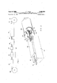
- FIG. 1 is a block diagram of a steel stri hardening process line as used in the practice of the invention
- FIG. 2 is a diagrammatic perspective view of the transition between the transition zone and the quench unit
- FIG. 3 is an end view of the quench unit and its support arrangement as used in the practice of the invention.
- FIG. 4 is a side View of the apparatus shown in FIG. 3; an
- FIG. 5 is a sectional view of the quench unit taken along the line 5-5 of FIG. 4.
- FIG. 1 A processing line for treating stainless steel strip in a hardening and tempering operation to provide a strip of suitable metallurgical characteristics capable of having formed thereon a durable, high quality shaving edge is shown diagrammatically in FIG. 1. That processing line.
- the strip 10 processed in this line is in the order of 0.2 inch wide and 0.0015 inch thick.
- the steel employed in the preferred embodiment has the following composition range:
- the strip is then further cooled by passage through a water cooled quench block assembly 18 and then a freeze cooling unit 20' which is operated at approximately 90 F.
- the steel is then passed through tempering furnace 22, which is maintained at approximately 500 F., and then through inspection station 24 where the quality of the processed steel is inspected.
- the heat treated steel is then wound on take-up reel 26.
- That assembly includes a table on which a quench block structure 52 is supported.
- that quench block structure includes a body 54 which defines a passage 56 to which are connected inlet and outlet tubes 58 for the flow of cooling water through the body.
- Supported on the body is a series of lower quench plates 60 held in place by clamp elements 62, and a corresponding series of upper quench plates 64.
- These quench plates in this particular embodiment are manufactured of carbide (Carboloy grade 907) and each quench plate includes a central ridge 66 which contacts the upper surface of the steel strip 10 (not shown in FIGURE 5) as it moves over the series of lower plates 60.
- the ends of the quench plate ridges 66 are radiused in the order of 0.025 inch and provide a smooth transitional surface at the entry of the strip to the quench unit.
- a lock nut 76 cooperates with bracket 70 to lock screw 72 in position so that the stop member 74 may hold the series of upper quench plates in the desired position relative to the body 54.
- the quench block unit is coupled to table 50 by side plate elements 80, 82 which are secured to the sides of the base 54 of the quench block by means of screws 84.
- Projecting laterally from the platform 50 are two arms 85, each having an upstanding bracket 86 which receives an adjustment screw 88 that is coupled respectively to the blocks and 82 through a universal joint structure 90.
- a stop structure 92 is provided at the read end of platform 50 which limits the backward movement of the quench block assembly.
- Platform 50 is secured by pin to an upstanding bracket member 102 which in turn is pivotally secured to intermediate member 104 by transverse pin 106.
- Member 104 includes an arm 108 that projects laterally from it which receives an adjusting screw 110. This adjusting screw, at its upper end, engages platform '50 and when moved pivots that platform '50 about the axis defined by pin 100 in a level adjustment operation.
- At the rear end of intermediate member 104 is still another adjusting screw 112 the upper end which is secured to the rear end of platform 50 by block 114 so that rotation of screw 112 produces rotation of platform 50 about the axis defined by pin 106.
- Intermediate member 104 is supported on a base structure by adjustment screw 122 and is guided by rods 124, 126.
- Adjumstment screw 122 is received in threaded relation by base 120 and is secured to intermediate member 104 so that rotation of screw 122 produces vertical movement of platform 50 (via intermediate member 104).
- Base 120 is secured on rails by bracket members 132.
- the transition zone structure 16 includes a cylindrical tube 136 which has disposed in it an insert 140 that has a channel of U-shaped configuration as indicated in FIG. 2 that extends the full length of the tube and which is secured in position by four locking screws located in the sides of the tube.
- the channel has two side walls 144, 146 and a base wall 148.
- the end of base wall 148 is an abrupt straight line surface.
- This insert is a material of low thermal conductivity and a satisfactory material is Marinitean asbestos fiber material having an inorganic binder.
- strip 10 is passed through the processing line at a continuous and uniform rate of speed and is continually sensed for a dish condition by a suitable gauging element, a satisfactory gauging element being disclosed in the co-pending patent application Ser. No. 568,- 874, filed Oct. 14, 1966, now Patent No. 3,367,688 and assigned to the same assignee as this application.
- the quench block assembly Upon detection of a dish condition the quench block assembly is lowered relative to the guide surface 146 so that the strip steel 10 is forced over the sharp edge 150 at the output end of insert 140.
- the upper surface of the strip steel is similarly subjected to a transition of somewhat lesser magnitude by the first upper quench plate 64.
- This stressing of the strip is effective to remove the dish condition and result in a substantially fiat steel strip, the edge of which is suitable for sharpening by high volume mass production techniques to a durable, high quality razor edge.
- the orientation of the dish condition be of concave downward configuration. With such configuration, the steel strip is more uniformly guided by the insert 140 in the transition zone and creation of stains (oxidation) on the finished strip is minimized.
- the steel strip during the hardening process is subjected to mechanical working at a point in the process where the condition of the steel is such that it can be mechanically worked without adverse effect (such as marring) on its surface and yet the steel is in such condition that enables a dish condition to be removed through relatively minor manipulation of the steel prior to completion of the austenite to martensite transformation.
- a continuous strip steel treating system comprising a heating furnace, a quenching unit, an air cooled zone interposed between said furnace and said quenching unit, said air cooled zone having a member providing a support surface for said strip, adjustment'mechanism for varying the relative height of said quench unit and said support member to subject said strip to a differential stress at the transition between said zone and said quenching unit for reducing transverse curvature of the strip, an inspection station, and a feedback link connected between said inspection station and said adjustment mechanism for operating said .adjustment mechanism in response to detection at said inspection station of excessive transverse curvature of said strip.
- a continuous strip steel treating system comprising a heating furnace, a quenching unit, an air cooled zone interposed between said furnace and said quenching unit, said air cooled zone having a member providing a support surface for said strip, said support member including a horizontal support surface that extends substantially the entire distance between said furnace and said quenching unit, and adjustment mechanism for varying the relative height of said quench unit and said support member to subject said strip to a differential stress at the transition between said zone and said quenching unit for reducing transverse curvature of the strip.
- said support member further includes a pair of spaced vertical surfaces that function to guide the edges of said strip during passage through said zone.
- a continuous strip steel treating system comprising a heating furnace, a quenching unit, an air cooled zone interposed between said furnace and said quenching unit, said quenching unit including a water cooled lower quench plate and a juxtaposed air cooled upper quench plate between which plates said strip is passed for quenching, said air cooled zone having a member providing a support surface for said strip, and adjustment mechanism for varying the relative height of said quench unit .and said support member to subject said strip to a diiferential stress at the transition between said zone and said quenching unit for reducing transverse curvature of the strip.
- said razor blade steel is stainless steel strip in the order of 0.0015 to 0.0039 inch in thickness
- said furnace is adapted to heat said strip to a temperature in the order of 2000 F.
- said zone is of a length such that the temperature of the strip at the exit of said zone is in the order of 320 F.
- a continuous strip steel treating system comprising a heating furnace for heating a steel strip to produce austenite, means for feeding steel strip through said furnace along a predetermined path, quenching means for converting austenite in said steel strip to martensite, an edge structure disposed between said furnace and said quenching means and lying transversely to the path of the strip, and adjustment mechanism for varying the position of said edge structure relative to said predetermined path to subject said strip to a diiferential stress at the transition between said edge structure and said quenching means for reducing transverse curvature of the strip.
- edge structure has a relatively sharp edge disposed generally perpendicular to the direction of strip movement along said predetermined path.
Landscapes
- Chemical & Material Sciences (AREA)
- Engineering & Computer Science (AREA)
- Mechanical Engineering (AREA)
- Physics & Mathematics (AREA)
- Thermal Sciences (AREA)
- Crystallography & Structural Chemistry (AREA)
- Materials Engineering (AREA)
- Metallurgy (AREA)
- Organic Chemistry (AREA)
- Heat Treatment Of Strip Materials And Filament Materials (AREA)
- Heat Treatment Of Sheet Steel (AREA)
Applications Claiming Priority (1)
| Application Number | Priority Date | Filing Date | Title |
|---|---|---|---|
| US58688066A | 1966-10-14 | 1966-10-14 |
Publications (1)
| Publication Number | Publication Date |
|---|---|
| US3466022A true US3466022A (en) | 1969-09-09 |
Family
ID=24347474
Family Applications (1)
| Application Number | Title | Priority Date | Filing Date |
|---|---|---|---|
| US586880A Expired - Lifetime US3466022A (en) | 1966-10-14 | 1966-10-14 | Apparatus for processing of strip metal in a continuous manner to remove undesired curvature |
Country Status (7)
| Country | Link |
|---|---|
| US (1) | US3466022A (de) |
| BR (1) | BR6793867D0 (de) |
| CH (1) | CH494820A (de) |
| ES (2) | ES346016A1 (de) |
| GB (1) | GB1199629A (de) |
| NL (1) | NL6713920A (de) |
| SE (1) | SE335546B (de) |
Cited By (3)
| Publication number | Priority date | Publication date | Assignee | Title |
|---|---|---|---|---|
| WO2011037759A3 (en) * | 2009-09-24 | 2011-09-01 | Ati Properties, Inc. | Processes for reducing flatness deviations in alloy articles |
| TWI564095B (zh) * | 2014-04-01 | 2017-01-01 | 三千金屬工業股份有限公司 | 滑軌之軌道結構及其製法 |
| CN114085980A (zh) * | 2021-11-12 | 2022-02-25 | 江西振扬精密机械制造有限公司 | 一种十字轴热处理系统及其处理工艺 |
Families Citing this family (1)
| Publication number | Priority date | Publication date | Assignee | Title |
|---|---|---|---|---|
| EP4261295A1 (de) * | 2022-04-12 | 2023-10-18 | "Credo" Stahlwarenfabrik Gustav Kracht GmbH & Co. KG | Verfahren zur herstellung einer klinge |
Citations (7)
| Publication number | Priority date | Publication date | Assignee | Title |
|---|---|---|---|---|
| US1732244A (en) * | 1928-03-29 | 1929-10-22 | Samuel I Salzman | Method of hardening steel |
| US1924099A (en) * | 1931-11-20 | 1933-08-29 | United States Steel Corp | Thermally hardening steel |
| US1994839A (en) * | 1931-08-04 | 1935-03-19 | H O Swoboda Inc | Apparatus for treating materials |
| US2131505A (en) * | 1938-08-16 | 1938-09-27 | Henry M Garsson | Treating steel |
| US2182060A (en) * | 1937-06-18 | 1939-12-05 | Triangle Mechanical Lab Corp | Apparatus for treating strip steel |
| US2686639A (en) * | 1953-06-11 | 1954-08-17 | United States Steel Corp | Apparatus for tensioning strip |
| US3252693A (en) * | 1963-05-07 | 1966-05-24 | Jones & Laughlin Steel Corp | Control system for continuous annealing lines and the like |
-
1966
- 1966-10-14 US US586880A patent/US3466022A/en not_active Expired - Lifetime
-
1967
- 1967-10-12 SE SE13984/67A patent/SE335546B/xx unknown
- 1967-10-12 CH CH1426167A patent/CH494820A/de not_active IP Right Cessation
- 1967-10-13 BR BR193867/67A patent/BR6793867D0/pt unknown
- 1967-10-13 ES ES346016A patent/ES346016A1/es not_active Expired
- 1967-10-13 NL NL6713920A patent/NL6713920A/xx unknown
- 1967-10-13 GB GB46737/67A patent/GB1199629A/en not_active Expired
-
1968
- 1968-11-26 ES ES360700A patent/ES360700A1/es not_active Expired
Patent Citations (7)
| Publication number | Priority date | Publication date | Assignee | Title |
|---|---|---|---|---|
| US1732244A (en) * | 1928-03-29 | 1929-10-22 | Samuel I Salzman | Method of hardening steel |
| US1994839A (en) * | 1931-08-04 | 1935-03-19 | H O Swoboda Inc | Apparatus for treating materials |
| US1924099A (en) * | 1931-11-20 | 1933-08-29 | United States Steel Corp | Thermally hardening steel |
| US2182060A (en) * | 1937-06-18 | 1939-12-05 | Triangle Mechanical Lab Corp | Apparatus for treating strip steel |
| US2131505A (en) * | 1938-08-16 | 1938-09-27 | Henry M Garsson | Treating steel |
| US2686639A (en) * | 1953-06-11 | 1954-08-17 | United States Steel Corp | Apparatus for tensioning strip |
| US3252693A (en) * | 1963-05-07 | 1966-05-24 | Jones & Laughlin Steel Corp | Control system for continuous annealing lines and the like |
Cited By (6)
| Publication number | Priority date | Publication date | Assignee | Title |
|---|---|---|---|---|
| WO2011037759A3 (en) * | 2009-09-24 | 2011-09-01 | Ati Properties, Inc. | Processes for reducing flatness deviations in alloy articles |
| AU2010298597B2 (en) * | 2009-09-24 | 2015-05-07 | Ati Properties, Inc. | Processes for reducing flatness deviations in alloy articles |
| US9822422B2 (en) | 2009-09-24 | 2017-11-21 | Ati Properties Llc | Processes for reducing flatness deviations in alloy articles |
| US10260120B2 (en) | 2009-09-24 | 2019-04-16 | Ati Properties Llc | Processes for reducing flatness deviations in alloy articles |
| TWI564095B (zh) * | 2014-04-01 | 2017-01-01 | 三千金屬工業股份有限公司 | 滑軌之軌道結構及其製法 |
| CN114085980A (zh) * | 2021-11-12 | 2022-02-25 | 江西振扬精密机械制造有限公司 | 一种十字轴热处理系统及其处理工艺 |
Also Published As
| Publication number | Publication date |
|---|---|
| BR6793867D0 (pt) | 1973-01-23 |
| SE335546B (de) | 1971-06-01 |
| ES346016A1 (es) | 1969-02-16 |
| ES360700A1 (es) | 1970-07-16 |
| GB1199629A (en) | 1970-07-22 |
| CH494820A (de) | 1970-08-15 |
| NL6713920A (de) | 1968-04-16 |
Similar Documents
| Publication | Publication Date | Title |
|---|---|---|
| JP5218435B2 (ja) | 厚鋼板の制御冷却方法 | |
| US4440584A (en) | Method and apparatus for cooling steel sheet | |
| US3390871A (en) | Apparatus for the controlled cooling of rods | |
| JP2010537046A (ja) | ステンレス鋼帯板の冷却において平坦度を制御する方法および装置 | |
| JP4604564B2 (ja) | 厚鋼板の制御冷却方法及び装置 | |
| JPS6315329B2 (de) | ||
| JP5759103B2 (ja) | 熱処理炉における金属材の制御方法 | |
| US3708354A (en) | Method and apparatus for measuring and controlling the continuous annealing of a long length of metal tubing | |
| US3466022A (en) | Apparatus for processing of strip metal in a continuous manner to remove undesired curvature | |
| US4921037A (en) | Method and apparatus for introducing differential stresses in endless flexible metallic casting belts for enhancing belt performance in continuous metal casting machines | |
| US3615923A (en) | Method for processing of strip metal in a continuous manner to remove undesired curvature | |
| US3765660A (en) | Beam quenching apparatus and method | |
| JP3596460B2 (ja) | 厚鋼板の熱処理方法およびその熱処理設備 | |
| US3262822A (en) | Method for continuous quenching of aluminum strip | |
| JPS60247485A (ja) | 金属管の連続溶接方法及び装置 | |
| US4826542A (en) | Method for forming bainite | |
| US2897698A (en) | Continuous treatment of metal strip | |
| US20230257842A1 (en) | Correction apparatus for correcting the planarity of a metal strip and related correction method | |
| US3545244A (en) | Proximity yoke apparatus | |
| US3403541A (en) | Method and apparatus for cooling workpieces | |
| JPS5938287B2 (ja) | 複合組織鋼板の連続焼鈍方法および装置 | |
| US3350188A (en) | Apparatus for forming ribbon with lateral force means | |
| JPS5942050B2 (ja) | ステンレス鋼材固溶化熱処理時の冷却方法 | |
| JPS5823550A (ja) | 溶融金属急冷法により製造される薄帯板の巾方向板厚制御法 | |
| JP3282714B2 (ja) | 高温鋼板の冷却方法 |