US3473285A - Method of erection of concrete reinforcing structures - Google Patents
Method of erection of concrete reinforcing structures Download PDFInfo
- Publication number
- US3473285A US3473285A US671839A US3473285DA US3473285A US 3473285 A US3473285 A US 3473285A US 671839 A US671839 A US 671839A US 3473285D A US3473285D A US 3473285DA US 3473285 A US3473285 A US 3473285A
- Authority
- US
- United States
- Prior art keywords
- bars
- reinforcing
- bar
- column
- bundle
- Prior art date
- Legal status (The legal status is an assumption and is not a legal conclusion. Google has not performed a legal analysis and makes no representation as to the accuracy of the status listed.)
- Expired - Lifetime
Links
- 230000003014 reinforcing effect Effects 0.000 title description 66
- 238000000034 method Methods 0.000 title description 13
- 229910000831 Steel Inorganic materials 0.000 description 10
- 238000010276 construction Methods 0.000 description 10
- 239000010959 steel Substances 0.000 description 10
- 230000006835 compression Effects 0.000 description 9
- 238000007906 compression Methods 0.000 description 9
- 210000001503 joint Anatomy 0.000 description 9
- 239000007787 solid Substances 0.000 description 9
- 230000002787 reinforcement Effects 0.000 description 5
- 238000003466 welding Methods 0.000 description 3
- 239000004606 Fillers/Extenders Substances 0.000 description 2
- 238000004873 anchoring Methods 0.000 description 2
- 238000003491 array Methods 0.000 description 2
- 230000000694 effects Effects 0.000 description 2
- 230000007935 neutral effect Effects 0.000 description 2
- HAAITRDZHUANGT-UHFFFAOYSA-N 1-[2-[(7-chloro-1-benzothiophen-3-yl)methoxy]-2-(2,4-dichlorophenyl)ethyl]imidazole;nitric acid Chemical compound O[N+]([O-])=O.ClC1=CC(Cl)=CC=C1C(OCC=1C2=CC=CC(Cl)=C2SC=1)CN1C=NC=C1 HAAITRDZHUANGT-UHFFFAOYSA-N 0.000 description 1
- 240000004282 Grewia occidentalis Species 0.000 description 1
- 208000024780 Urticaria Diseases 0.000 description 1
- 238000005452 bending Methods 0.000 description 1
- 239000003638 chemical reducing agent Substances 0.000 description 1
- 230000009194 climbing Effects 0.000 description 1
- 230000001427 coherent effect Effects 0.000 description 1
- 230000000295 complement effect Effects 0.000 description 1
- 238000006073 displacement reaction Methods 0.000 description 1
- 238000004804 winding Methods 0.000 description 1
Images


Classifications
-
- E—FIXED CONSTRUCTIONS
- E04—BUILDING
- E04C—STRUCTURAL ELEMENTS; BUILDING MATERIALS
- E04C5/00—Reinforcing elements, e.g. for concrete; Auxiliary elements therefor
- E04C5/16—Auxiliary parts for reinforcements, e.g. connectors, spacers, stirrups
- E04C5/162—Connectors or means for connecting parts for reinforcements
- E04C5/163—Connectors or means for connecting parts for reinforcements the reinforcements running in one single direction
Definitions
- This invention relates to construction work for buildings and other structures and is specifically concerned with the erection of internal steel reinforcements for vertical load-bearing concrete columns and other structures.
- Any practical concrete column, wall, or other concrete structure for supporting appreciable loads must be reinforced by steel bars. These bars must be spliced whenever the height of the structure exceeds the practical length of a single bar.
- the completed column or other structure is frequently subjected to eccentric loading. That is, the load may be applied on one side or the other of the neutral vertical axis. Such loading, at any given crosssection through the column, will compress (squeeze) the column on one side of the neutral axis and at the other side the column will be in tension (stretched).
- the reinforcing bars are preferably grouped in compact bundles, at least two reinforcing bars in each bundle.
- the bundles are spaced in an array corresponding to the four corners of the square column.
- additional bundles of reinforcing bars may be used intermediate the corners.
- the bundles are spaced periodically along the opposite sides of the wall. The minimum requirement would be three bundles of bars, fora round column.
- the ironworker must move around the reinforcing structure to apply ties and stirrups to complete a rigid structure.
- the workman himself exerts a small eccentric load, tending to bend or sway the column, particularly as the column becomes more flexible at substantial heights.
- movement of a scaffold around the reinforcing structure, during erection may be awkard and quite difficult; it may be necessary to proceed in fits and starts, adding re-bars, removing a scaffold, then adding ties and stirrups, bringing the scaffold back, etc.
- a high reinforcing structure can be erected with great facility, at minimum cost, and without appreciable bending in the course of construction, by using mechanical clamp splices in bundled-bar construction.
- Each clamp joint or splice employs a splicing sleeve which encompasses the end-to'end butt joint between adjacent ends of two reinforcing bars; the sleeve is backed by the solid portion of an adjacent bar in the same bundle.
- the splicing sleeve is mounted on the upper end of the shorter bar, and the bar length is extended in height by inserting into the sleeve the lower end of the next bar as one stage of erection. The sleeve is then contracted to form a strong joint in the bar.
- the bundles are tied together at frequent intervals, and stirrups are tied about the column as it is extended. The entire structure is free-standing and selfsupporting, enabling the workman to ascend the column to any required height.
- each spliced bar develops strength in compression at a given cross-section. Being backed or abutted by the solid portion of an adjacent bar or bars in the bundle, the bundle as a whole develops a minimum of 50% strength in tension even at a cross-section through a splice. Consequently, and as the primary object of the present invention, both welded and lapped joints can be dispensed with; no dislocations are experienced at the joints because even 50% strength in tension is more than enough to carry the weight of the workman and his tools representing an eccentric loading tending to bend the reinforcing structure, as well as any eccentric loading of the structure itself.
- this method of splicing of the individual bars inherently and effectively maintains accurate vertical alignment all the way up the structure, with no special effort required on the part of the ironworker other than continuing application of ties and stirrups, and affords close control of the finished form of the reinforcing members.
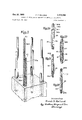
- FIG. 1 is a perspective view of a reinforcing colurrm constructed in accordance with the principles of the present invention
- FIG. 1A is a fragmentary perspective view showing the manner in which reinforcing rods are butted incidental to extending an upright;
- FIG. 2 is a perspective view illustrating starting procedures for constructing a reinforcing column in accordance with the present invention
- FIGS. 2A through 2D are detail views illustrative of the construction of a splice
- FIGS. 3, 4 and 5 are detail perspective views, fragmen tary, illustrating subsequent stages of erecting a reinforcing column in accordance with the present invention
- FIG. 6 is a fragmented perspective view on an enlarged scale of a portion of the column shown in FIG. 1;
- FIG. 7 is a fragmented perspective view illustrating a workman in a working position, having ascended the column.
- FIGS. 8 and 9 are diagrammatic views illustrating the scope of the principles of the present invention.
- the preferred embodiment of the invention is one wherein the reinforcing structure as a whole is composed of four or more laterally spaced bundles of steel reinforcing bars, each bundle presenting three reinforcing bars in back-to-back longitudinal abutted relationship, the bars being assembled from reinforcing bar sections square butted end-to-end.
- the invention is also applicable in principle to spaced bundles three in number, say in a triangular array, and to bundles composed of only two uprights.
- FIG. 1 illustrates a steel reinforcing structure 20 as a whole, comprising steel reinforcing bars of the usual kind, and preferably those that present welts or ribs for good anchoring relationship with respect to the concrete to be subsequently poured in completion of the reinforced structure.
- Structure 20 is a column, as illustrated, but could be a hearing wall or any other vertically extending load-bearing structure.
- the reinforcing column 20, FIG. 1 comprises four laterally spaced bundles of reinforcing bars 21, 22, 23 and 24 symmetrically and rather uniformly spaced from one another in a fourcorner array, but as noted, the invention is equally applicable in principle to bundles in other arrays.
- each bundle, FIG. 1 comprises a plurality of bars; in the embodiment illustrated, the uprights or bars in each bundle are three in number as shown by the bars 26, 27 and 28 in one bundle. However, there may be four or more bars in each bundle, or as few as two.
- Each bar or upright is assembled from individual reinforcing bar sections of predetermined length presenting square ends E1 and E2 to be brought into full concentric, butted relationship (see FIG. 1A).
- the first stage of construction assumes previous pouring of a footing 30 to the desired depth and cross-section.
- dowels hereinafter referred to as first stage reinforcing bars 26A, 27A and 28A
- first stage reinforcing bars 26A, 27A and 28A are embedded in the footing at a location corresponding to the location of each reinforcing bundle.
- Each dowel is the start or beginning of a long, continuous bar upright.
- the first stage reinforcing bars are in a relatively tight pack so as to be in longitudinal back-to-back rela tion.
- the upper free ends E1 of the first stage bars are displaced at three different elevations for reasons apparent from the description to follow.
- a sleeve 32 is assembled on the free upper end E1 of the shortest first stage reinforcing bar 28A, FIG. 2A.
- sleeve 32 is a splicing sleeve usable in conjunction with a tightening wedge 33 of the character disclosed in FIGS. 7 and 8 of Reiland Patent No. 3,245,189.
- the steps in completing each splice are illustrated in FIGS. 2A-2D.
- the splicing sleeve 32 is open at both ends and is split longitudinally in such a fashion as to present a pair of wedge flanges 35 and 36, FIGS. 2A and 2B, which diverge in a downward direction.
- the splicing sleeve is thin walled (about /s") so as to be capable of telescoping over the upper free end of the reinforcing bar to which it is related without substantial interference with the desired back-to-back or longitudinal abutting relation which is to prevail among the bundled bars.
- the splicing sleeve is backed up by engagement with the ad jacent reinforcing bar as 26A or 27A.
- a second stage reinforcing bar 283, FIGS. 2A, 2B and 3, is in effect inserted as an extender into the unoccupied upper extension of the splicing sleeve 32, and in any event the splicing sleeve and the two bars 28A and 2813 to be end butted are so manipulated as to assure that the ends E1 and E2 are square butted, FIG. 2B in full concentric bearing, with the splicing sleeve 32 encompassing the opposed ends of the reinforcing bars 28A and 28B.
- a complemental wedge member or key 33 is slipped over the wedging flanges 35 and 36 of the sleeve 32.
- the rear side of the wedge member is formed with a groove 33G, defined by a pair of spaced flanges as the complement of the spread flanges 35 and 36 of the splicing sleeve.
- the wedge member may be manually tightened on the sleeve 32 to start the clamping action.
- the wedge member is driven home by repeated hammer blows as a consequence of which the sleeve 32 is constricted and tightly binds the butted end portions of the first and second stage reinforcing bars 28A and 28B.
- the continuous bar as thus far constructed from the butted bars 28A and 28B, develops the full strength of a solid bar from the standpoint of compression at the cross-section of the joint.
- the bundle of bars, at the joint between the 'butted ends -E1 and E2 possesses at least the strength in tension of any of the backing bar or bars not interrupted at that joint.
- these two uprights considered together afford the full strength in compression of both and the strength in tension is at least 50% of the maximum for the two-bar bundle, being equal to the strength in tension of the solid bar 26A.
- the strength in tension at the joint becomes at least 66 and if the solid portion of a fourth bar were to be present at the joint, the strength in tension becomes at least 75% of the maximum for the entire bundle.
- the tensile strength at each joint is appreciably greater than the percentages given. above, once the joint is completed and the concrete is poured and set, because the combination compression and cast joints ultimately formed within the completed column are themselves capable of withstanding some stress in tension.
- the tensile load characteristics of the column can easily be maintained within normal design limits, particularly if the joints within any column are always maintained at a spacing sufficient to develop the full strength of the bars by bond in the concrete of the completed structure. In a typical column or other structure, this spacing may be approximately forty times the diameter of the largest rod employed in any upright reinforcing bundle; as illustrated in FIG. 8, the required termination spacing will vary somewhat with different structural configurations.
- any desired order of staging may be followed, but in most instances the next longer starting bar 27A, FIG. 4, will be selected and extended in a second stage operation of construction, utilizing a reinforcing bar 27B, substantially the same length and diameter as the bar 28B.
- a reinforcing bar 27B substantially the same length and diameter as the bar 28B.
- another splicing clamp sleeve 32', FIG. 4 is assembled on the free upper end of the first stage bar 27A, and the subsequent reinforcing bar is inserted into the sleeve 32' to extend the related upright one stage higher.
- the ends of the bars 27A and 27B are brought into end-butted relation within sleeve 32, sleeve 32' being backed up or supported in part itself by the opposed solid portion of the previously assembled bar 28B and by bar 26A.
- FIG. 5 is a repetition in that the longest reinforcing bar in the initial or starting set, bar 26A, is joined at its upper end to the lower end of a reinforcing bar 26B, again repeating the splicing step with a third constrictive splicing sleeve 32".
- Bar 26B is substantially the same length and diameter as bars 27B and 28B.
- the three bars for each stage of each bundle are all of equal length, though complete stages may vary in length. Consequently, the displacement in elevation which originally prevailed among the free terminal ends of the bars, FIG. 2, continues to prevail as the reinforcing structure is extended.
- each bar in each bundle is extended by an equal amount in length by repeated splices, characterizing successive stages of erection repeated in sequence around the column.
- FIG. 6 illustrates the reinforcing column intermediate the lower and upper ends.
- each stage of extension is characterized by capping the free upper ends of lower reinforcing rods with splicing sleeves as 32 while backing each sleeve with a solid or unspliced portion of at least one adjacent lower rod in the bundle, inserting into the upper end of the sleeves the lower ends of the next stage or upper reinforcing bars, completing the clamp splices, and so on until the desired height for the reinforcing column is achieved.
- the extender or upper bars are free standing at all times as can be visualized from FIG. 7.
- the clamping sleeves 32 maintain the original straight alignment presented by the starting bars, FIG. 2, assuring the desired integrity of back-to-back bar abutment as well as sleeve-to-bar abutment.
- FIG. 7 for example, the final bars presenting short ends are topped off in the reverse sense of the starting operation shown in FIG. 2, and the column or other structure is capped at the top in the usual fashion.
- stirrups 40 FIGS. 1 and 6, which are secured to the bar bundles at spaced intervals and in encompassing relationship. Typical spacing may be approximately on 15" centers.
- stirrups afford a convenient ladder enabling the workman to ascend the column, as seen in FIG. 7.
- the stirrups 40 are preferably afforded by small diameter, easily bent reinforcing rods; preferably, the stirrups are secured in place by wire ties 41, FIGS. 1A and 6. Bundle integrity may be further assured by wire ties 41 at other strategic locations.
- the invention is equally applicable to different arrangements, and in FIGS. 8 and 9 this is disclosed in a diagrammatic sense.
- the bundles may comprise two, three or four bars, FIG. 8; and the bundles themselves may assume different arrays as shown in the wall and column configurations in FIG. 9.
- a primary advantage of the present invention may be viewed as centered on considerations of the strength in compression and the strength in tension referred to above, and this will be readily apparent in its practical application from FIG. 7.
- the reinforcing column is erected in a towering sense, higher and higher, it is necessary for the workman to ascend the column, FIG. 7.
- the weight of the workman and efforts entailed in assemblage as work is completed around the column necessarily apply eccentric loading to the column as a whole. Consequently, some rods are placed in compression and others in tension, but these forces are fully resisted both from the standpoint of workman safety and integrity of the joints.
- a method of erecting a free-standing internal steel reinforcement for a vertical load-bearing concrete structural member comprising the following steps:
- FRANK ABBOTT Pnmary Exammer 2 A method according to claim 1 including the step P. C. FAW, JR., Assistant Examiner of repeatedly encompassing the bundles, as a group, with 15 rigid stirrups so spaced as to enable a workman per- US. Cl. X.R. forming the erection to ascend the stirrups of the rein- 653 726 forcing column in erecting the column.
Landscapes
- Engineering & Computer Science (AREA)
- Architecture (AREA)
- Civil Engineering (AREA)
- Structural Engineering (AREA)
- Reinforcement Elements For Buildings (AREA)
Description
Oct. 21, 1969 F. F. REILAND 3,
METHOD OF ERECTION OF CONCRETE REINFORCING STRUCTURES Filed Sept. 29, 1967 4 Sheets-Sheet 1 20 Fin Inventor- Frank D. Rei land F. F. RElLAND Oct. 21, 1969 METHOD OF ERECTION OF CONCRETE REINFORCING STRUCTURES Filed Sept. 29, 1967 4 Sheets-Sheet l .n.l Ill lllll Inventor Frank D. Rel land 3 ZUMuqWwI/Dm +orne1 F. F. REILAND Oct. 21, 1969 METHOD OF ERECTION OF CONCRETE REINFORCING STRUCTURES Filed Sept. 29, 1967 4 Sheets-Sheet 3 Inventor Frank I). Rei land H'Horn eg F- F. REILAND Oct. 21, 1969 METHOD OF ERECTION OF CONCRETE REINFORCING STRUCTURES Filed Sept. 29, 1967 4 Sheets-Sheet 4 lnven'tbr 'Fank D.Rei|and "5 5 am' m M. qtouuw United States Patent 3,473,285 METHOD OF ERECTTON 0F CONCRETE REINFORCING STRUCTURES Frank F. Reiland, Chicago, Ill., assignor to Gateway Erectors, Inc., Chicago, Ill., a corporation of Delaware Filed Sept. 29, 1967, Ser. No. 671,339
Int. Cl. E04c 3/30; E04g 21/00; E0411 12/16 US. Cl. 52-741 3 Claims ABSTRACT OF THE DISCLOSURE A method of erecting a free-standing steel reinforcement for a vertical load-bearing concrete structure, using reinforcing bars compacted in individual bundles. The bars in each bundle are so dimensioned or selected as to present free upper ends displaced at different elevations. Each bundle is extended in height by repeatedly joining butting extension bars thereto and clamping the extens on bars in place with constrictive splicing sleeves while maintaining the bars in substantial back-to-back longitudinal engagement. Once the structure is started, all subsequent reinforcing bars are of substantially the same length, in each erection stage, so that the joint afforded by the splicing sleeve is backed by the solid or unspliced portion of an adjacent bar in the bundle. Consequently the column or other structure presents full strength in compression and also has substantial strength in tension to resist eccentric loading. During erection, the workman ascends the column and works around the column in the course of erection, the bars supporting his weight and all equipment required for erection; no scaffolding is needed. Integrity of the abutting relationships of the bars is maintained by ties; rigid stirrups encompass the bundles and afford a convenient support for the ironworker.
This invention relates to construction work for buildings and other structures and is specifically concerned with the erection of internal steel reinforcements for vertical load-bearing concrete columns and other structures.
Any practical concrete column, wall, or other concrete structure for supporting appreciable loads must be reinforced by steel bars. These bars must be spliced whenever the height of the structure exceeds the practical length of a single bar.
The completed column or other structure is frequently subjected to eccentric loading. That is, the load may be applied on one side or the other of the neutral vertical axis. Such loading, at any given crosssection through the column, will compress (squeeze) the column on one side of the neutral axis and at the other side the column will be in tension (stretched).
Superior reinforcmeent in a concrete column or other structure is realized by strategic distribution of the steel reinforcement bars in bundles. Thus, in a square column for example, the reinforcing bars are preferably grouped in compact bundles, at least two reinforcing bars in each bundle. The bundles are spaced in an array corresponding to the four corners of the square column. In a large column, additional bundles of reinforcing bars may be used intermediate the corners. In a wall, the bundles are spaced periodically along the opposite sides of the wall. The minimum requirement would be three bundles of bars, fora round column.
Regardless of geometry, an appreciable problem is presented in splicing the bars in the course of extending the reinforcing structure to a desired height, whenever that height exceeds the height of a workman. One obvious way of extending the structure is by Welding additional bars end-to-end onto each reinforing bar in each bundle. The cost factors, however, are considerable; the cost of Patented Oct. 21, 1969 labor itself presents many multiplying factors and expensive equipment must be moved to and from the site. Moreover, the bars will not support welding equipment during erection. An extensible scaffold must be erected for this purpose.
So-called lap splicing has been proposed, but again there are several emphatic objections. The lap splice itself requires a congestion of numerous short splicing dowels which must be both assembled and tightened about the joint as a time-consuming operation. In winding the tie wire around the lap joint, the butted reinforcing bars tend to get out of alignment. Indeed, it is often virtually impossible to hold the bars in alignment, even if a scaffold is used to give the iron-worker special support and stability.
Furthermore, with both welded and lap-spliced joints, or joints of any other form, the ironworker must move around the reinforcing structure to apply ties and stirrups to complete a rigid structure. In moving around the reinforcing column the workman himself exerts a small eccentric load, tending to bend or sway the column, particularly as the column becomes more flexible at substantial heights. More importantly, movement of a scaffold around the reinforcing structure, during erection, may be awkard and quite difficult; it may be necessary to proceed in fits and starts, adding re-bars, removing a scaffold, then adding ties and stirrups, bringing the scaffold back, etc.
A high reinforcing structure can be erected with great facility, at minimum cost, and without appreciable bending in the course of construction, by using mechanical clamp splices in bundled-bar construction. Each clamp joint or splice employs a splicing sleeve which encompasses the end-to'end butt joint between adjacent ends of two reinforcing bars; the sleeve is backed by the solid portion of an adjacent bar in the same bundle. 'Ihis entails the use of at least two bars for each bundle, with their ends at different elevations, The splicing sleeve is mounted on the upper end of the shorter bar, and the bar length is extended in height by inserting into the sleeve the lower end of the next bar as one stage of erection. The sleeve is then contracted to form a strong joint in the bar. The bundles are tied together at frequent intervals, and stirrups are tied about the column as it is extended. The entire structure is free-standing and selfsupporting, enabling the workman to ascend the column to any required height.
Moreover, the free-standing reinforcement structure requires little or no special equipment to continue its erection. Each spliced bar develops strength in compression at a given cross-section. Being backed or abutted by the solid portion of an adjacent bar or bars in the bundle, the bundle as a whole develops a minimum of 50% strength in tension even at a cross-section through a splice. Consequently, and as the primary object of the present invention, both welded and lapped joints can be dispensed with; no dislocations are experienced at the joints because even 50% strength in tension is more than enough to carry the weight of the workman and his tools representing an eccentric loading tending to bend the reinforcing structure, as well as any eccentric loading of the structure itself.
In the practice of the construction method of the present invention, individual joints in the bundles are completed using mechanical compression clamp splices of the kind described in my earlier Patents Nos. 3,245,189, 3,245,190 and 3,340,667. By using mechanical compression clamp splice devices of this kind, there is no necessity for the workman to carry heavy or complex welding equipment up to the column or other structure of reinforcing bars as they are erected. Thus, the erection of the reinforcing uprights for a tall structure that would require a variable height scaffold or other cumbersome support for the workman is dispensed with entirely. Furthermore, this method of splicing of the individual bars inherently and effectively maintains accurate vertical alignment all the way up the structure, with no special effort required on the part of the ironworker other than continuing application of ties and stirrups, and affords close control of the finished form of the reinforcing members.
Other and further objects of the present invention Will be apparent from the following description and claims and are illustrated in the accompanying drawings which, by way of illustration, show a preferred embodiment of the present invention and the principles thereof and what is now considered to be the best mode contemplated for applying these principles. Other embodiments of the invention embodying the same or equivalent principles may be used and structural changes may be made as desired by those skilled in the art without departing from the present invention.
In the drawings:
FIG. 1 is a perspective view of a reinforcing colurrm constructed in accordance with the principles of the present invention;
FIG. 1A is a fragmentary perspective view showing the manner in which reinforcing rods are butted incidental to extending an upright;
FIG. 2 is a perspective view illustrating starting procedures for constructing a reinforcing column in accordance with the present invention;
FIGS. 2A through 2D are detail views illustrative of the construction of a splice;
FIGS. 3, 4 and 5 are detail perspective views, fragmen tary, illustrating subsequent stages of erecting a reinforcing column in accordance with the present invention;
FIG. 6 is a fragmented perspective view on an enlarged scale of a portion of the column shown in FIG. 1;
FIG. 7 is a fragmented perspective view illustrating a workman in a working position, having ascended the column; and
FIGS. 8 and 9 are diagrammatic views illustrating the scope of the principles of the present invention.
The preferred embodiment of the invention is one wherein the reinforcing structure as a whole is composed of four or more laterally spaced bundles of steel reinforcing bars, each bundle presenting three reinforcing bars in back-to-back longitudinal abutted relationship, the bars being assembled from reinforcing bar sections square butted end-to-end. However, the invention is also applicable in principle to spaced bundles three in number, say in a triangular array, and to bundles composed of only two uprights.
Before explaining in detail the manner in which a reinforcing structure is erected under and in accordance with the present invention, attention is directed to FIG. 1 which serves to establish the basis for terminology employed herein. Thus, FIG. 1 illustrates a steel reinforcing structure 20 as a whole, comprising steel reinforcing bars of the usual kind, and preferably those that present welts or ribs for good anchoring relationship with respect to the concrete to be subsequently poured in completion of the reinforced structure. Structure 20 is a column, as illustrated, but could be a hearing wall or any other vertically extending load-bearing structure.
In the embodiment illustrated, the reinforcing column 20, FIG. 1, comprises four laterally spaced bundles of reinforcing bars 21, 22, 23 and 24 symmetrically and rather uniformly spaced from one another in a fourcorner array, but as noted, the invention is equally applicable in principle to bundles in other arrays. In any event, each bundle, FIG. 1, comprises a plurality of bars; in the embodiment illustrated, the uprights or bars in each bundle are three in number as shown by the bars 26, 27 and 28 in one bundle. However, there may be four or more bars in each bundle, or as few as two. Each bar or upright is assembled from individual reinforcing bar sections of predetermined length presenting square ends E1 and E2 to be brought into full concentric, butted relationship (see FIG. 1A).
As will be apparent in FIG. 6, the uprights in each column are rather tightly nested in substantial longitudinal iback-to-back relationship. This plays a significant role in achieving desired strength in accordance with the present invention, as explained in more detail hereinafter. In the specifications to follow, the description is restricted to the staged construction and extension of one bundle of reinforcing bars bearing in mind that the description is equally applicable to the other bundles since the construction as a Whole is symmetrical throughout.
The first stage of construction, FIG. 2, assumes previous pouring of a footing 30 to the desired depth and cross-section. In the course of preparing the footing, dowels, hereinafter referred to as first stage reinforcing bars 26A, 27A and 28A, are embedded in the footing at a location corresponding to the location of each reinforcing bundle. Each dowel is the start or beginning of a long, continuous bar upright. It will be observed in FIG. 3 that the first stage reinforcing bars are in a relatively tight pack so as to be in longitudinal back-to-back rela tion. The upper free ends E1 of the first stage bars are displaced at three different elevations for reasons apparent from the description to follow.
In continuation of the first stage of assembly, a sleeve 32 is assembled on the free upper end E1 of the shortest first stage reinforcing bar 28A, FIG. 2A. Preferably, sleeve 32 is a splicing sleeve usable in conjunction with a tightening wedge 33 of the character disclosed in FIGS. 7 and 8 of Reiland Patent No. 3,245,189. The steps in completing each splice are illustrated in FIGS. 2A-2D. Thus, the splicing sleeve 32 is open at both ends and is split longitudinally in such a fashion as to present a pair of wedge flanges 35 and 36, FIGS. 2A and 2B, which diverge in a downward direction. The splicing sleeve is thin walled (about /s") so as to be capable of telescoping over the upper free end of the reinforcing bar to which it is related without substantial interference with the desired back-to-back or longitudinal abutting relation which is to prevail among the bundled bars. In effect, the splicing sleeve is backed up by engagement with the ad jacent reinforcing bar as 26A or 27A.
A second stage reinforcing bar 283, FIGS. 2A, 2B and 3, is in effect inserted as an extender into the unoccupied upper extension of the splicing sleeve 32, and in any event the splicing sleeve and the two bars 28A and 2813 to be end butted are so manipulated as to assure that the ends E1 and E2 are square butted, FIG. 2B in full concentric bearing, with the splicing sleeve 32 encompassing the opposed ends of the reinforcing bars 28A and 28B. While maintaining this relationship, a complemental wedge member or key 33 is slipped over the wedging flanges 35 and 36 of the sleeve 32. As shown in FIG. 3, the rear side of the wedge member is formed with a groove 33G, defined by a pair of spaced flanges as the complement of the spread flanges 35 and 36 of the splicing sleeve.
As shown in FIG. 2C, the wedge member may be manually tightened on the sleeve 32 to start the clamping action. As the final step of completion of the splice, the wedge member is driven home by repeated hammer blows as a consequence of which the sleeve 32 is constricted and tightly binds the butted end portions of the first and second stage reinforcing bars 28A and 28B.
It will be appreciated that the continuous bar as thus far constructed from the butted bars 28A and 28B, develops the full strength of a solid bar from the standpoint of compression at the cross-section of the joint. At the same time the bundle of bars, at the joint between the 'butted ends -E1 and E2, possesses at least the strength in tension of any of the backing bar or bars not interrupted at that joint. In other words, when viewing the solid bar 26A as one reinforcing upright, FIG. 3, and the spliced bars 28A and 28B as a second reinforcing upright, these two uprights considered together afford the full strength in compression of both and the strength in tension is at least 50% of the maximum for the two-bar bundle, being equal to the strength in tension of the solid bar 26A. In taking into account the second bar 27A, the strength in tension at the joint becomes at least 66 and if the solid portion of a fourth bar were to be present at the joint, the strength in tension becomes at least 75% of the maximum for the entire bundle.
Actually, the tensile strength at each joint is appreciably greater than the percentages given. above, once the joint is completed and the concrete is poured and set, because the combination compression and cast joints ultimately formed within the completed column are themselves capable of withstanding some stress in tension. The tensile load characteristics of the column can easily be maintained within normal design limits, particularly if the joints within any column are always maintained at a spacing sufficient to develop the full strength of the bars by bond in the concrete of the completed structure. In a typical column or other structure, this spacing may be approximately forty times the diameter of the largest rod employed in any upright reinforcing bundle; as illustrated in FIG. 8, the required termination spacing will vary somewhat with different structural configurations.
Any desired order of staging may be followed, but in most instances the next longer starting bar 27A, FIG. 4, will be selected and extended in a second stage operation of construction, utilizing a reinforcing bar 27B, substantially the same length and diameter as the bar 28B. Thus, another splicing clamp sleeve 32', FIG. 4, is assembled on the free upper end of the first stage bar 27A, and the subsequent reinforcing bar is inserted into the sleeve 32' to extend the related upright one stage higher. Again, the ends of the bars 27A and 27B are brought into end-butted relation within sleeve 32, sleeve 32' being backed up or supported in part itself by the opposed solid portion of the previously assembled bar 28B and by bar 26A.
The next operation, FIG. 5, is a repetition in that the longest reinforcing bar in the initial or starting set, bar 26A, is joined at its upper end to the lower end of a reinforcing bar 26B, again repeating the splicing step with a third constrictive splicing sleeve 32". Bar 26B is substantially the same length and diameter as bars 27B and 28B. Preferably, in all subsequent staging the three bars for each stage of each bundle are all of equal length, though complete stages may vary in length. Consequently, the displacement in elevation which originally prevailed among the free terminal ends of the bars, FIG. 2, continues to prevail as the reinforcing structure is extended. Thus, each bar in each bundle is extended by an equal amount in length by repeated splices, characterizing successive stages of erection repeated in sequence around the column. This can be readily appreciated from the legends applied to FIG. 6 which illustrates the reinforcing column intermediate the lower and upper ends. Thus, each stage of extension is characterized by capping the free upper ends of lower reinforcing rods with splicing sleeves as 32 while backing each sleeve with a solid or unspliced portion of at least one adjacent lower rod in the bundle, inserting into the upper end of the sleeves the lower ends of the next stage or upper reinforcing bars, completing the clamp splices, and so on until the desired height for the reinforcing column is achieved. The extender or upper bars are free standing at all times as can be visualized from FIG. 7. The clamping sleeves 32 maintain the original straight alignment presented by the starting bars, FIG. 2, assuring the desired integrity of back-to-back bar abutment as well as sleeve-to-bar abutment. When the desired height is finally reached,
FIG. 7 for example, the final bars presenting short ends are topped off in the reverse sense of the starting operation shown in FIG. 2, and the column or other structure is capped at the top in the usual fashion.
In the course of erecting the reinforcing structure, integrity of back-to-back abutting between the longitudinal extent of bars, as Well as sleeve-tobar backing, is further assured by rigid stirrups 40, FIGS. 1 and 6, which are secured to the bar bundles at spaced intervals and in encompassing relationship. Typical spacing may be approximately on 15" centers. These stirrups afford a convenient ladder enabling the workman to ascend the column, as seen in FIG. 7. The stirrups 40 are preferably afforded by small diameter, easily bent reinforcing rods; preferably, the stirrups are secured in place by wire ties 41, FIGS. 1A and 6. Bundle integrity may be further assured by wire ties 41 at other strategic locations.
As noted above, the invention is equally applicable to different arrangements, and in FIGS. 8 and 9 this is disclosed in a diagrammatic sense. Thus, the bundles may comprise two, three or four bars, FIG. 8; and the bundles themselves may assume different arrays as shown in the wall and column configurations in FIG. 9.
A primary advantage of the present invention may be viewed as centered on considerations of the strength in compression and the strength in tension referred to above, and this will be readily apparent in its practical application from FIG. 7. Thus, as the reinforcing column is erected in a towering sense, higher and higher, it is necessary for the workman to ascend the column, FIG. 7. Both in the course of ascent and in the course of working around the column, the weight of the workman and efforts entailed in assemblage as work is completed around the column, necessarily apply eccentric loading to the column as a whole. Consequently, some rods are placed in compression and others in tension, but these forces are fully resisted both from the standpoint of workman safety and integrity of the joints. Depending upon the height requirement for the column, and limitations on commercial sizes of reinforcing rods, two to forty splices may be required to reach the top of the column. In actual on-site testing, the present method of construction has been employed successfully for columns thirty feet high, such that code requirements appear to be the only limit.
Of essentially equal importance is the inherent selfaligning nature of the bundles of bars erected in accordance with the present invention. Within each bundle, addition of further bar lengths does not create alignment problems; the bundle stays compact and coherent from top to bottom. If one bar is dropped, in upper stories, the remainder of the bars in the bundle are still in tight nested alignment. If bar size is reduced, using reducers as described in the aforementioned Reiland patents, the overall bundle can be easily brought back into compact alignment and inherently remains centered over the lower large-diameter portion of the bundle.
I claim:
1. A method of erecting a free-standing internal steel reinforcement for a vertical load-bearing concrete structural member comprising the following steps:
(a) anchoring at least three bundles of first-stage steel reinforcing bars, at least two bars per bundle, at spaced positions within the periphery of a footing for said structural member, the bars in each bundle being disposed in compact, vertically-projecting, mutual longitudinal-abutting relation and having their upper ends terminating at substantially different elevations;
(b) mounting a second-stage steel reinforcing bar on the shortest first-stage bar of each bundle, in endabutting relation;
(c) clamping said second-stage bar to said shortest first-stage bar with a constrictive mechanical clamp 7 8 comprising a thin-walled open-ended splicing sleeve in each bundle are repeatedly tied together in the course encompassing the butted ends of the 'bars, each of extending the column. splicing sleeve being backed by at least one adjacent unspliced reinforcing bar of the same bundle; References Clted (d) continuing erection by repetition of steps (b) and 5 UNITED STATES PATENTS (c) for the other bars in each bundle, and repeating 1 895 828 1/1933 Van Inwagen 57--22 X for additional stages, using bars of approximately equal length in each stage; 3,245,190 4/ 1966 Relland 5 (e) and climbing the resulting structure, during step ((1), so that the reinforcing bars themselves support 10 FOREIGN PATENTS the erecting Workman and any required erection 7531522 1933 Franceequipment during the performance of the subsequent stages of erection as specified in step (d). FRANK ABBOTT Pnmary Exammer 2. A method according to claim 1 including the step P. C. FAW, JR., Assistant Examiner of repeatedly encompassing the bundles, as a group, with 15 rigid stirrups so spaced as to enable a workman per- US. Cl. X.R. forming the erection to ascend the stirrups of the rein- 653 726 forcing column in erecting the column.
3. A method according to claim 1 in which the bars
Applications Claiming Priority (1)
| Application Number | Priority Date | Filing Date | Title |
|---|---|---|---|
| US67183967A | 1967-09-29 | 1967-09-29 |
Publications (1)
| Publication Number | Publication Date |
|---|---|
| US3473285A true US3473285A (en) | 1969-10-21 |
Family
ID=24696071
Family Applications (1)
| Application Number | Title | Priority Date | Filing Date |
|---|---|---|---|
| US671839A Expired - Lifetime US3473285A (en) | 1967-09-29 | 1967-09-29 | Method of erection of concrete reinforcing structures |
Country Status (1)
| Country | Link |
|---|---|
| US (1) | US3473285A (en) |
Cited By (24)
| Publication number | Priority date | Publication date | Assignee | Title |
|---|---|---|---|---|
| US3659388A (en) * | 1969-11-18 | 1972-05-02 | Donald M Sirianni | Steel shell for use in building construction |
| US3918229A (en) * | 1974-05-28 | 1975-11-11 | Manfred P Schweinberger | Column base assembly |
| US4114344A (en) * | 1976-04-21 | 1978-09-19 | Imoco-Gateway Corporation | Concrete reinforcement splice with location tab |
| US4838737A (en) * | 1984-08-15 | 1989-06-13 | Quimby Harold L | Pier for supporting a load such as a foundation wall |
| US5392580A (en) * | 1992-05-06 | 1995-02-28 | Baumann; Hanns U. | Modular reinforcement cages for ductile concrete frame members and method of fabricating and erecting the same |
| US5404685A (en) * | 1992-08-31 | 1995-04-11 | Collins; Dennis W. | Polystyrene foamed plastic wall apparatus and method of construction |
| US20040238558A1 (en) * | 2003-05-26 | 2004-12-02 | Halfen Gmbh + Co. Kommanditgesellschaft | Device for Connecting Ends of Bars |
| US20050183381A1 (en) * | 2003-01-21 | 2005-08-25 | Rosenberg Jean G. | Method for manufacturing brakeless lightweight concrete poles |
| US20060284328A1 (en) * | 2005-05-25 | 2006-12-21 | Pantelides Chris P | FRP Composite wall panels and methods of manufacture |
| US20070199264A1 (en) * | 2006-02-24 | 2007-08-30 | Juergen Gruen | Fixing arrangement |
| EA010211B1 (en) * | 2007-05-23 | 2008-06-30 | Общество С Ограниченной Ответственностью «Научно-Технический И Экспериментально-Проектный Центр "Аркос"» | A reinforced concrete column with reinforcing steel pipes |
| US20090145074A1 (en) * | 2005-09-10 | 2009-06-11 | Kenichi Tsukamoto | Reinforcing body made of fiber-reinforced plastic |
| US20090178356A1 (en) * | 2008-01-15 | 2009-07-16 | Baumann Hanns U | Pre-cast concrete column and method of fabrication |
| US20130019542A1 (en) * | 2011-07-20 | 2013-01-24 | Bishop Richard B | Safe room ii |
| US8375678B1 (en) * | 2009-09-28 | 2013-02-19 | Felix E. Ferrer | Methods for construction of pre-fabricated modular reinforcement cages for concrete structures |
| US20140041333A1 (en) * | 2012-08-08 | 2014-02-13 | James Larkin | Device for securing one face wall mesh to vertical rebar and standard concrete forms |
| US20140235376A1 (en) * | 2009-11-23 | 2014-08-21 | Entrotech Composites, Llc | Reinforced Objects |
| US20140305062A1 (en) * | 2013-01-16 | 2014-10-16 | Rupert Heron | Masonry units and structures formed therefrom |
| US20150354162A1 (en) * | 2013-02-28 | 2015-12-10 | Elas Geotecnica S.R.L. | Reinforcement, structure and method for underground reinforced concrete constructions |
| US9267287B1 (en) * | 2014-01-22 | 2016-02-23 | Steven James Bongiorno | Pre-fabricated threaded bar assemblies |
| US9562355B2 (en) * | 2012-05-18 | 2017-02-07 | Neturen Co., Ltd. | Rebar structure and reinforced concrete member |
| US9890545B1 (en) * | 2016-11-14 | 2018-02-13 | Steven James Bongiorno | Erection system |
| EP3320147B1 (en) * | 2015-07-10 | 2021-10-13 | Soletanche Freyssinet | Method for constructing a foundation including a step of cutting-of |
| US20250109588A1 (en) * | 2022-06-13 | 2025-04-03 | Senvex Co., Ltd. | Prefabricated bracket assembly integrated to prefabricated column assembly for connecting pc beams |
Citations (3)
| Publication number | Priority date | Publication date | Assignee | Title |
|---|---|---|---|---|
| US1895828A (en) * | 1930-04-14 | 1933-01-31 | Bell Telephone Labor Inc | Wire splicing machine |
| FR753522A (en) * | 1933-03-31 | 1933-10-18 | Reinforced concrete column: new arrangement of reinforcements | |
| US3245190A (en) * | 1962-06-05 | 1966-04-12 | Gateway Erectors Inc | Metallically reinforced concrete structures |
-
1967
- 1967-09-29 US US671839A patent/US3473285A/en not_active Expired - Lifetime
Patent Citations (3)
| Publication number | Priority date | Publication date | Assignee | Title |
|---|---|---|---|---|
| US1895828A (en) * | 1930-04-14 | 1933-01-31 | Bell Telephone Labor Inc | Wire splicing machine |
| FR753522A (en) * | 1933-03-31 | 1933-10-18 | Reinforced concrete column: new arrangement of reinforcements | |
| US3245190A (en) * | 1962-06-05 | 1966-04-12 | Gateway Erectors Inc | Metallically reinforced concrete structures |
Cited By (29)
| Publication number | Priority date | Publication date | Assignee | Title |
|---|---|---|---|---|
| US3659388A (en) * | 1969-11-18 | 1972-05-02 | Donald M Sirianni | Steel shell for use in building construction |
| US3918229A (en) * | 1974-05-28 | 1975-11-11 | Manfred P Schweinberger | Column base assembly |
| US4114344A (en) * | 1976-04-21 | 1978-09-19 | Imoco-Gateway Corporation | Concrete reinforcement splice with location tab |
| US4838737A (en) * | 1984-08-15 | 1989-06-13 | Quimby Harold L | Pier for supporting a load such as a foundation wall |
| US5392580A (en) * | 1992-05-06 | 1995-02-28 | Baumann; Hanns U. | Modular reinforcement cages for ductile concrete frame members and method of fabricating and erecting the same |
| US5404685A (en) * | 1992-08-31 | 1995-04-11 | Collins; Dennis W. | Polystyrene foamed plastic wall apparatus and method of construction |
| US20050183381A1 (en) * | 2003-01-21 | 2005-08-25 | Rosenberg Jean G. | Method for manufacturing brakeless lightweight concrete poles |
| US20040238558A1 (en) * | 2003-05-26 | 2004-12-02 | Halfen Gmbh + Co. Kommanditgesellschaft | Device for Connecting Ends of Bars |
| US20060284328A1 (en) * | 2005-05-25 | 2006-12-21 | Pantelides Chris P | FRP Composite wall panels and methods of manufacture |
| US7856778B2 (en) * | 2005-05-25 | 2010-12-28 | University Of Utah Foundation | FRP composite wall panels and methods of manufacture |
| US20090145074A1 (en) * | 2005-09-10 | 2009-06-11 | Kenichi Tsukamoto | Reinforcing body made of fiber-reinforced plastic |
| US20070199264A1 (en) * | 2006-02-24 | 2007-08-30 | Juergen Gruen | Fixing arrangement |
| EA010211B1 (en) * | 2007-05-23 | 2008-06-30 | Общество С Ограниченной Ответственностью «Научно-Технический И Экспериментально-Проектный Центр "Аркос"» | A reinforced concrete column with reinforcing steel pipes |
| US20090178356A1 (en) * | 2008-01-15 | 2009-07-16 | Baumann Hanns U | Pre-cast concrete column and method of fabrication |
| US8375678B1 (en) * | 2009-09-28 | 2013-02-19 | Felix E. Ferrer | Methods for construction of pre-fabricated modular reinforcement cages for concrete structures |
| US8381479B1 (en) * | 2009-09-28 | 2013-02-26 | Felix E. Ferrer | Pre-fabricated modular reinforcement cages for concrete structures |
| US20140235376A1 (en) * | 2009-11-23 | 2014-08-21 | Entrotech Composites, Llc | Reinforced Objects |
| US20130019542A1 (en) * | 2011-07-20 | 2013-01-24 | Bishop Richard B | Safe room ii |
| US9562355B2 (en) * | 2012-05-18 | 2017-02-07 | Neturen Co., Ltd. | Rebar structure and reinforced concrete member |
| US20140041333A1 (en) * | 2012-08-08 | 2014-02-13 | James Larkin | Device for securing one face wall mesh to vertical rebar and standard concrete forms |
| US9097010B2 (en) * | 2012-08-08 | 2015-08-04 | James Larkin | Device for securing one face wall mesh to vertical rebar and standard concrete forms |
| US20140305062A1 (en) * | 2013-01-16 | 2014-10-16 | Rupert Heron | Masonry units and structures formed therefrom |
| US8973322B2 (en) * | 2013-01-16 | 2015-03-10 | Rupert Heron | Masonry units and structures formed therefrom |
| US20150354162A1 (en) * | 2013-02-28 | 2015-12-10 | Elas Geotecnica S.R.L. | Reinforcement, structure and method for underground reinforced concrete constructions |
| US9267287B1 (en) * | 2014-01-22 | 2016-02-23 | Steven James Bongiorno | Pre-fabricated threaded bar assemblies |
| EP3320147B1 (en) * | 2015-07-10 | 2021-10-13 | Soletanche Freyssinet | Method for constructing a foundation including a step of cutting-of |
| US9890545B1 (en) * | 2016-11-14 | 2018-02-13 | Steven James Bongiorno | Erection system |
| US20250109588A1 (en) * | 2022-06-13 | 2025-04-03 | Senvex Co., Ltd. | Prefabricated bracket assembly integrated to prefabricated column assembly for connecting pc beams |
| US12276104B1 (en) * | 2022-06-13 | 2025-04-15 | Senvex Co., Ltd. | Prefabricated bracket assembly integrated to prefabricated column assembly for connecting PC beams |
Similar Documents
| Publication | Publication Date | Title |
|---|---|---|
| US3473285A (en) | Method of erection of concrete reinforcing structures | |
| US3938294A (en) | Method of erecting a frame structure for buildings | |
| KR101794683B1 (en) | Launching Method of Composite CFT Truss Girder Bridge | |
| WO2017013694A1 (en) | Framework structure and construction method for same | |
| US10106972B1 (en) | Precast concrete building elements and assemblies thereof, and related methods | |
| US10760273B1 (en) | Apparatus and methods for providing continuous structural support to footings and interconnected hollow core wall units | |
| JPH0518003A (en) | Joining method for steel tube concrete columns and half-precast reinforced concrete columns. | |
| JPH07300817A (en) | Concrete filled steel pipe truss bridge pier and its construction method | |
| EP1235964B9 (en) | Method for the construction of a prestressed structure and prestressed structure thus obtained | |
| JP2002250006A (en) | Multi-column composite bridge pier structure and constructing method therefor | |
| JP4014050B2 (en) | Steel pipe temporary facility construction method | |
| JP3020343B2 (en) | Column base structure using hollow tube and method of constructing the same | |
| JP3401598B2 (en) | High pier and its construction method | |
| JP4103574B2 (en) | Construction method of beam-like structure | |
| JPH0959933A (en) | Filled coated steel tube concrete structure and construction method | |
| JP2000273946A (en) | Method for constructing reinforced concrete structure | |
| JP2974025B1 (en) | Construction method of large span large beam upper frame | |
| JP6340467B1 (en) | Ramen structure using sleeve wall and joining method thereof | |
| JP3606535B2 (en) | Assembling method of pier reinforcement frame | |
| JP7767696B2 (en) | PCa joint and its construction method | |
| US3218775A (en) | Column structure erection method | |
| CN217419350U (en) | Pier beam prestressed body external temporary consolidation construction structure | |
| JP3590561B2 (en) | Precast concrete block joining method | |
| JPH08239807A (en) | Composite column base structure | |
| JPH06264511A (en) | Pressure joining work method for post and beam |