US3495335A - Thickness-measuring instrument,particularly for enamelled wire - Google Patents
Thickness-measuring instrument,particularly for enamelled wire Download PDFInfo
- Publication number
- US3495335A US3495335A US613654A US3495335DA US3495335A US 3495335 A US3495335 A US 3495335A US 613654 A US613654 A US 613654A US 3495335D A US3495335D A US 3495335DA US 3495335 A US3495335 A US 3495335A
- Authority
- US
- United States
- Prior art keywords
- measuring
- disc
- instrument
- counter
- thickness
- Prior art date
- Legal status (The legal status is an assumption and is not a legal conclusion. Google has not performed a legal analysis and makes no representation as to the accuracy of the status listed.)
- Expired - Lifetime
Links
Images
Classifications
-
- G—PHYSICS
- G01—MEASURING; TESTING
- G01B—MEASURING LENGTH, THICKNESS OR SIMILAR LINEAR DIMENSIONS; MEASURING ANGLES; MEASURING AREAS; MEASURING IRREGULARITIES OF SURFACES OR CONTOURS
- G01B5/00—Measuring arrangements characterised by the use of mechanical techniques
- G01B5/08—Measuring arrangements characterised by the use of mechanical techniques for measuring diameters
- G01B5/10—Measuring arrangements characterised by the use of mechanical techniques for measuring diameters of objects while moving
Definitions
- the invention relates to an instrument for measuring the thickness of continuously moving filamentous or ribhon-shaped material, such as for enamelled wire, which is fed through a gap between an eccentrically rotatable disc provided with a re-adjusting spring and a curved, eccentrically mounted counter member.
- a wire-measuring instrument with mechanical gearing in which two vertical measuring rollers are positioned in a stand, and a counter-measuring roller, in the form of a measuring-bridge, is suspended for oscillation by means of spring-steel strips so that it is adjustable on the parallelogram principle and can follow the varying thicknesses of the wire.
- the invention has the object of providing a measuring instrument of new spatial form which has a sturdy construction; can be manufactured cheaply, enables direct reading, is easily adjustable to various measuring ranges, restricts any unauthorized setting of the accuracy of measurement and the spring strength.
- a thickness-measuring instrument in which the reading arrangement is arranged on a disc having an adjustable return spring enclosing the disc spindle holder.
- a measuring gap is formed between a disc and a counter-chamber which is movable in stages as a counter disc in the instrument housing and is fixedly positionable by means of holding parts such as a clamping screw and a holding screw.
- holding parts such as a clamping screw and a holding screw.
- the measuring range can be extended as necessary.
- a compact sturdy construction is obtained and it is not necessary to anchor the measuring instrument in a stand or to use it exclusively as a stationary instrument.
- the instrument does not require any electrical parts.
- a catch-block for holding a spring-actuation.
- the counter-member is carried out in the form of an anvil which in the individual case leads advantageously to having of material. Protection of the reading arrangement of the scale is aflorded along with more convenient reading by means of a window located above a scale on the measuring disc or the counter-disc.
- a simplified presentation of the counter-disc contains a slot for guiding the clamping screw which permits a continuous setting of the range and a reliable adjustment even during abrupt temperature changes. Further the measuring disc and counterdisc can be constructed with a removable cover, preferably containing a window.
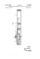
- FIGURE 1 is a longitudinal section through the thickness measuring instrument
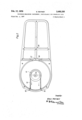
- FIGURE 2 is a plan view on FIGURE 1 with the cover of the instrument removed, and
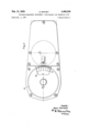
- FIGURE 3 is a plan view of the instrument with the cover in place.
- a circular measuring disc 10 is fixed to the upper stepped end of a spindle-holder 11 from which a spindle 12 extends downwardly and is mounted within the casing of a measuring instrument.
- the parts 10, 11, 12 form one piece.
- the rotatable measuring disc is mounted in the casing to rotate eccentrically (cf. FIGURE 3).
- Extending about the periphery of the spindle-holder 11 is an annular groove 14 arranged to receive a tension spring 15 which, in FIGURE 2, is secured at its outer end to pins 16.
- the spring 15 around the spindle-holder and thus, in an advantageous way, effects a unilateral pressure on the bearing pin which excludes a bearing movement of the measuring disc.
- Alteration of the returning force of the spring acting on the measuring disc can be efiected changing the 'point of attachment of the spring to a holding part, such as a catch-plate 17, on the spindle-holder 11.
- the measuring disc is limited against upward movement by a cover 18 which is fixed axially to the disc through the knob 19.
- a window 20 is provided through which a scale 21 located at the periphery of the measuring disc can be read.
- the catch-plate 17 is soldered in the groove of the spindle-holder (FIGURE 2).
- the counter-member forms with its rim a slit or gap 23 with the measuring disc into which the wire to be measured (not shown) is inserted.
- the counter-disc can be covered by a lid-shaped part 24, preferably provided with a window 25, which is removable for making alterations in the position of the disc.
- a slot 26 can be provided for a clamping screw 27, see FIG. 2 (adjustment easy-even during great variations in temperature) while the disc 22 itself is fixed by means of a holding-screw 28 secured in a part of the casing.
- the instrument works preferably in three measuring ranges for the following wire-thicknesses: 0.05-0.15 mm.; 0.15-0.25 mm.; 0.25-0.35 mm.
- the cover part 24 is taken olf, the holding screw 28 is slackened and the clamping screw 27 is released.
- the counter disc is mounted eccentrically, see FIG. 3, and it is manually rotated until the proper distance is established across the gap 23 between the counter disc and the measuring disc.
- the clamping screw 27 istightening for holding the counter-disc in position in the casing against any displacement for subsequent measurements and the holding screw is also tightened,
- the Spring can be set or reset to a different tension as desired.
- the knob 19 is released, the cover 18 and then the spindleholder 11 removed, whereby the spring-ends need not be removed from the pins 16. In this way the spring strength can beset easily as desired.
- This instrument ensures an accuracy of measurement of i2 and less.
- the manufacture of the instrument is simplified by making one or both of the measuring discs as simple circular discs.
- the window as is known inanother connection, is covered with a transparent foil and can be provided with a lens or the like for better reading. Due to the arrangement of the spring 15 consideration is taken of an important technical measurement requirement in that the return force acting on the measuring disc and the frictional force between the surface of the material being measured and the face of the measuring disc are opposed and will be equally great.
- the measuring range corresponds to a half-turn of the disc (180), cf. FIGURE 3. If the diameter of the measuring disc is 50 mm. for example and the mounting is displaced from the middle of the disc by 0.05 mm., there thus appear in the middle of the measuring range divisions for 2a altera tion in thickness at a distance of more than 1 mm. so that the alterations in thickness of 2p. are exactly readable without ditficulty.
- a further advantage consists in the fact that strips, filaments and wires at only slight measuring pressure at run-otf speeds of 4-5 metres per second for example, are satisfactorily measurable.
- the Wire or material to be checked is fed into the gap 23 between the discs.
- the counter-disc is stationary, however, when the wire contacts the measuring disc it will be rotated about its axis until the dimension of the gap corresponds to the diameter of the wire.
- the measuring disc will be rotated until the gap is of a suflicient dimension to permit the passage of the wire therethrough.
- the reading on the scale showing the displacement of the measuring disc from any fixed zeropoint, will indicate the dimension of the wire and is determined by adding the scale reading to the minimum gap opening.
- the scale can be arranged to afford a direct dimension reading. The return force of the spring will return the measuring disc as the diameter of the wire decreases while the frictional contact between the wire and the disc will rotate the measuring disc into the proper measuring position.
- the invention can also be varied in such a way that the Scale on the measuring disc is rotatable or adjustable as it is eccentrically adjustable.
- An instrument for measuring the thickness of filamentous strip and -wire material comprising a casing, a circular measuring disc eccentrically rotatably mounted in said casing and having a peripheral circumferential edge surface, a counter member having an edge surface being disposed in spaced facing relationship with the circumferential edge surface of said measuring disc and forming a slit therebetween arranged to receive the material to be measured, said counter member being adjustably positionable within said casing relative to said measuring disc for varying the slit dimension therebetween, said measuring disc having a scale formed on its surface about a portion of its circumferential edge, a spindle extending axially from said measuring disc for rotatably mounting said disc in said casing, a catch plate being secured to and extending laterally from said spindle, a tension spring being positioned about and in contact with said spindle and being secured to said casing, said tension spring being in interengaged contact with said catch plate for biasing said disc against the feed of material through the slit between said measuring disc and said counter member, means
- an extension of said spindle extends axially from said disc from the side thereof opposite to the side from which said spindle extends for rotatably mounting said disc in said casing, a cover member fitted on said extension and supported about at least a portion of its periphery on said casing so that said extension is rotatable with said dise relative to said cover, a knob fitted onto said extension for securing said cover to said disc for preventing displacement of said disc from said casing, and a window formed in said cover for reading the scale on said disc.
- said means for securing said counter member comprising a holding screw extending through said counter member for securing said counter member to said casing, a lid-shaped part removably fitted to said casing and covering said counter member, and a window in said lid-shaped part for viewing said counter member.
Landscapes
- Physics & Mathematics (AREA)
- General Physics & Mathematics (AREA)
- A Measuring Device Byusing Mechanical Method (AREA)
- Investigating Strength Of Materials By Application Of Mechanical Stress (AREA)
- Length Measuring Devices With Unspecified Measuring Means (AREA)
Applications Claiming Priority (1)
| Application Number | Priority Date | Filing Date | Title |
|---|---|---|---|
| DEE0030997 | 1966-02-05 |
Publications (1)
| Publication Number | Publication Date |
|---|---|
| US3495335A true US3495335A (en) | 1970-02-17 |
Family
ID=7074821
Family Applications (1)
| Application Number | Title | Priority Date | Filing Date |
|---|---|---|---|
| US613654A Expired - Lifetime US3495335A (en) | 1966-02-05 | 1967-02-02 | Thickness-measuring instrument,particularly for enamelled wire |
Country Status (4)
| Country | Link |
|---|---|
| US (1) | US3495335A (de) |
| AT (1) | AT280629B (de) |
| GB (1) | GB1175087A (de) |
| NL (1) | NL6701674A (de) |
Cited By (1)
| Publication number | Priority date | Publication date | Assignee | Title |
|---|---|---|---|---|
| CN104654978A (zh) * | 2015-02-02 | 2015-05-27 | 苏州圣利线缆有限公司 | 一种漆包线线径手工检测的治具 |
Citations (4)
| Publication number | Priority date | Publication date | Assignee | Title |
|---|---|---|---|---|
| FR492086A (fr) * | 1916-07-20 | 1919-06-27 | Eugene Beaudrey | Appareil de vérification des corps de gaine-relais pour obus et autres pièces analogues |
| US1803284A (en) * | 1928-03-10 | 1931-04-28 | Brown & Sharpe Mfg | Measuring gauge |
| US2268521A (en) * | 1937-01-30 | 1941-12-30 | Wilson Evan George | Thickness measuring device |
| US3155109A (en) * | 1961-08-29 | 1964-11-03 | Res Specialties Co | Liquid supply apparatus |
-
1967
- 1967-02-02 US US613654A patent/US3495335A/en not_active Expired - Lifetime
- 1967-02-03 GB GB5303/67A patent/GB1175087A/en not_active Expired
- 1967-02-03 AT AT102367A patent/AT280629B/de not_active IP Right Cessation
- 1967-02-03 NL NL6701674A patent/NL6701674A/xx unknown
Patent Citations (4)
| Publication number | Priority date | Publication date | Assignee | Title |
|---|---|---|---|---|
| FR492086A (fr) * | 1916-07-20 | 1919-06-27 | Eugene Beaudrey | Appareil de vérification des corps de gaine-relais pour obus et autres pièces analogues |
| US1803284A (en) * | 1928-03-10 | 1931-04-28 | Brown & Sharpe Mfg | Measuring gauge |
| US2268521A (en) * | 1937-01-30 | 1941-12-30 | Wilson Evan George | Thickness measuring device |
| US3155109A (en) * | 1961-08-29 | 1964-11-03 | Res Specialties Co | Liquid supply apparatus |
Cited By (1)
| Publication number | Priority date | Publication date | Assignee | Title |
|---|---|---|---|---|
| CN104654978A (zh) * | 2015-02-02 | 2015-05-27 | 苏州圣利线缆有限公司 | 一种漆包线线径手工检测的治具 |
Also Published As
| Publication number | Publication date |
|---|---|
| NL6701674A (de) | 1967-08-07 |
| AT280629B (de) | 1970-04-27 |
| GB1175087A (en) | 1969-12-23 |
Similar Documents
| Publication | Publication Date | Title |
|---|---|---|
| US3967383A (en) | Circumference gauge and recording method | |
| JPH06194103A (ja) | 直線測定装置 | |
| US2388582A (en) | Method of and apparatus for measuring center spacing | |
| US3979960A (en) | Compression tester | |
| US4061022A (en) | Hair testing apparatus | |
| US2254313A (en) | Gauging apparatus | |
| ES454062A1 (es) | Aparato para medir la ortogonalidad y la longitud de pasti- llas. | |
| US2206817A (en) | Precision spirit level | |
| US2360581A (en) | Optical indicator | |
| US2655073A (en) | Optical thickness gauge | |
| US2763068A (en) | Thread gauge | |
| US3292266A (en) | Test gage | |
| SU419714A1 (ru) | Индикаторный прибор для контроля шириныи несимметричности расположения пазовпрямоугольного сечения | |
| US2019741A (en) | Gauging apparatus | |
| US3636636A (en) | Radius-setting gauge | |
| US3266457A (en) | Indicating instrument | |
| JPS63279133A (ja) | 糸張力測定装置 | |
| US2338190A (en) | Linear-dimension gauge or comparator | |
| US2207480A (en) | Taper measuring caliper | |
| US2863221A (en) | Micrometer comparator | |
| US2290940A (en) | Apparatus for making pressureless measurements | |
| US2703007A (en) | Surface smoothness gauge | |
| US1679501A (en) | Indicator gauge | |
| US2412380A (en) | Gauging device | |
| US2458009A (en) | Square root radial averager |