US3497782A - Battery operated clock circuit - Google Patents
Battery operated clock circuit Download PDFInfo
- Publication number
- US3497782A US3497782A US636035A US3497782DA US3497782A US 3497782 A US3497782 A US 3497782A US 636035 A US636035 A US 636035A US 3497782D A US3497782D A US 3497782DA US 3497782 A US3497782 A US 3497782A
- Authority
- US
- United States
- Prior art keywords
- transistor
- circuit
- coil
- current
- oscillator
- Prior art date
- Legal status (The legal status is an assumption and is not a legal conclusion. Google has not performed a legal analysis and makes no representation as to the accuracy of the status listed.)
- Expired - Lifetime
Links
Images

Classifications
-
- G—PHYSICS
- G04—HOROLOGY
- G04C—ELECTROMECHANICAL CLOCKS OR WATCHES
- G04C3/00—Electromechanical clocks or watches independent of other time-pieces and in which the movement is maintained by electric means
- G04C3/04—Electromechanical clocks or watches independent of other time-pieces and in which the movement is maintained by electric means wherein movement is regulated by a balance
- G04C3/06—Electromechanical clocks or watches independent of other time-pieces and in which the movement is maintained by electric means wherein movement is regulated by a balance using electromagnetic coupling between electric power source and balance
- G04C3/065—Electromechanical clocks or watches independent of other time-pieces and in which the movement is maintained by electric means wherein movement is regulated by a balance using electromagnetic coupling between electric power source and balance the balance controlling gear-train by means of static switches, e.g. transistor circuits
-
- G—PHYSICS
- G04—HOROLOGY
- G04C—ELECTROMECHANICAL CLOCKS OR WATCHES
- G04C3/00—Electromechanical clocks or watches independent of other time-pieces and in which the movement is maintained by electric means
-
- G—PHYSICS
- G04—HOROLOGY
- G04C—ELECTROMECHANICAL CLOCKS OR WATCHES
- G04C3/00—Electromechanical clocks or watches independent of other time-pieces and in which the movement is maintained by electric means
- G04C3/16—Electromechanical clocks or watches independent of other time-pieces and in which the movement is maintained by electric means incorporating an electro-dynamic continuously rotating motor
- G04C3/165—Electromechanical clocks or watches independent of other time-pieces and in which the movement is maintained by electric means incorporating an electro-dynamic continuously rotating motor comprising a mechanical regulating device influencing the electromotor
Definitions
- This invention pertains to a battery operated clock circuit of the type wherein an electromechanical oscillator produces a train of accurately timed pulses for driving a pulse type clock motor.
- the drive and pickup coils are wound about a common core and a single magnet is employed.
- This magnet is mounted on a flat torsion spring so as to oscillate under the intluence of the drive coil.
- An NPN silicon oscillator transistor receives the signal induced in the pickup coil, amplifies the signals and returns them to the drive coil so as to form an electromechanical oscillator.
- the same signals are applied to the base of a PNP germanium amplifier transistor which applies the amplified current pulses to the stator windings of a synchronous pulse motor.
- the circuits are so arranged that the oscillator and amplifier transistors are in their on or off states at the same time.
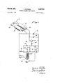
- FIG. 1 is a partially schematic, partially pictorial representation of the circuit of this invention
- FIG. 2 is a sectional view of a battery operated clock showing the components thereof.
- FIG. 3 is a perspective view of the mechanical oscillator used in the present invention.
- FIG. 1 there is illustrated a circuit including the pickup coil 10 and the drive coil 12 of an electromechanical oscillator. As illustrated, these coils are wound on the same core.
- the pickup coil 10 is connected in the base circuit of the oscillator transistor 14, which is an NPN silicon transistor.
- a fifty microfarad capacitor 16 is connected between the emitter electrode of transistor 14 and the other end of the pickup coil 10.
- a 10,000 ohm resistor 18 and a .1 microfarad capacitor 20 are connected in parallel with one another between the collector electrode of transistor 14 and the other end of the pickup coil 10.
- a 4,700 ohm resistor 22 is connected between the collector electrode of transistor 14 and one end of drive coil 12.
- drive coil 12 is connected to a 47,000 ohm resistor 24 and to the positive terminal of a battery 26.
- the other end of the resistor 24 is connected to the common junction of capacitor 16, pickup coil 10, resistor 18 and capacitor 20.
- the collector electrode of transistor 14 is also connected through a 10,000 ohm resistor 28 to the base of a switching transistor 30, which is also an NPN silicon transistor similar to transistor 14. In the illustrated embodiment, both these transistors are General Electric 2N2926.
- the emitter of transistor 30 is connected to the emitter of transistor 14 and to the negative side of a 1.5 volt battery 26.
- a two microfarad capacitor 32 is connected across the collector-emitter terminals of transistor 30 and the field coils 34, 36 of the clock motor are connected in series between the collector electrode of transistor 30 and the positive terminal of battery 26.
- the field coils are mounted upon a U-shaped laminated stator member 38 terminating a pair of U-shaped sections 40, 42 which encircle a permanent magnet rotor 44 (FIG. 2).
- FIG. 2 illustrates the manner in which the various components of the invention may be positioned within the clock casing.
- the clock casing 46 includes the pulse type permanent magnet synchronous motor comprising the field coils 34, 36 mounted upon the stator member 38 having the U-shaped sections 40, 42.
- the ends of the U-shaped sections form pole pieces 48, 50, 52, 54 adjacent the rotor 44.
- a housing 56 contains the battery 26 of FIG. 1.
- the rotor 44 is coupled in driving engagement with a gear train 58 for driving a pair of clock hands (not shown) by means of a concentric shaft mechanism 60.
- the mechanical oscillator 62 is mounted on one end of the clock base plate 64. It comprises a pair of support members 66, 68 which support therebetween a flat spring wire torsion member 70 between spaced pairs of clamping bars 72. 74. Mounted upon the torsion member is a partially disc shaped permanent magnet 76 positioned to extend into a rectangular opening 78 in a coil form 80 upon which are found the pickup coil and drive coil 12.
- the torsion member 70 oscillates at a natural frequency, depending upon its length between the clamping bars 72, 74 and its tension. Oscillation of the torsion member 70 causes the permanent magnet 76 to also oscillate, thereby setting up an alternating magnetic field in pickup coil 10.
- resistor 18 self-biases transistor 14 so that its operating point is near saturation.
- magnet 76 oscillates within the pickup coil 10; it induces an alternating current in the pickup coil which, when applied to the base of transistor 14, drives the transistor alternately into and away from saturation.
- the voltage at the collector is low, the transistor 14 being in its on condition.
- maximum current will be passing through the drive coil 12 for rotating the magnet 76.
- this transistor As the low voltage on the collector of transistor 14 is applied through resistor 28 to the base of transistor 30, this transistor, which is operated in the switching mode, is in its high impedance state.
- the collector-emitter current passing through this transistor is at a minimum so that the field coils 34, 36 of the motor are basically deenergized.
- the capacitor 16 provides a low impedance current path for the signals induced in pickup coil 10 and, at the same time, blocks DC. current flow from battery 26 to the drive coil 12.
- Capacitor 20 provides a low impedance path for high frequency oscillations that may occur due to coupling between coils 10 and 12 to prevent transistor 14 from going into high frequency oscillations.
- oscillator transistor 14'- will be self biased near saturation. Thus, its output impedance is low and the switching transistor 30 is on, energizing the motor coils. As the oscillations build up, signals from the pickup coil drive the operating point of transistor 14 away from saturation and into its high impedance state for about a half cycle and back into saturation for the rest of the cycle. The effect of these oscillations is to drive transistor 30 into a high impedance state from its originally low impedance state which then turns the motor coils off in preparation for the next pulse.
- An electromechanical oscillator circuit for timing driving pulses to a pulse-type synchronous motor comprising:
- first current control transistor means biased near saturation and having a normally low impedance state and a high impedance state in series with said drive means and said voltage source, said first current control transistor means being responsive to said alternating, current signal to transfer to said high impedance state when said alternating current signal is of a preselected polarity, the conductivity of said first current control transistor means being necessary for operation of said synchronous motor;
- second current control means having a low impedance state and a high impedance state in series with said synchronous motor and said voltage source, said second current control means being responsive to current flow through said first current control transistor means and having its impedance states reversed relative thereto.
- each of said first and second current control means is an NPN transistor.
- said first current control transistor means includes said pickup means in its base circuit and wherein said second current control transistor is operated in the switching mode and has its base terminal connected to the collector terminal of said first transistor.
- each of said first and second transistors is an NPN transistor.
Landscapes
- Physics & Mathematics (AREA)
- General Physics & Mathematics (AREA)
- Engineering & Computer Science (AREA)
- Electromagnetism (AREA)
- Power Engineering (AREA)
- Electromechanical Clocks (AREA)
- Control Of Motors That Do Not Use Commutators (AREA)
Applications Claiming Priority (1)
| Application Number | Priority Date | Filing Date | Title |
|---|---|---|---|
| US63603567A | 1967-05-04 | 1967-05-04 |
Publications (1)
| Publication Number | Publication Date |
|---|---|
| US3497782A true US3497782A (en) | 1970-02-24 |
Family
ID=24550116
Family Applications (1)
| Application Number | Title | Priority Date | Filing Date |
|---|---|---|---|
| US636035A Expired - Lifetime US3497782A (en) | 1967-05-04 | 1967-05-04 | Battery operated clock circuit |
Country Status (5)
| Country | Link |
|---|---|
| US (1) | US3497782A (de) |
| CH (2) | CH501960A (de) |
| DE (1) | DE1773349A1 (de) |
| FR (1) | FR1562628A (de) |
| GB (1) | GB1200518A (de) |
Cited By (2)
| Publication number | Priority date | Publication date | Assignee | Title |
|---|---|---|---|---|
| US4075540A (en) * | 1975-07-15 | 1978-02-21 | Kabushiki Kaisha Daini Seikosha | Stepping motor for timepiece |
| US4891567A (en) * | 1987-07-16 | 1990-01-02 | Minebea Co., Ltd. | Brushless DC motor having an outer rotor |
Citations (1)
| Publication number | Priority date | Publication date | Assignee | Title |
|---|---|---|---|---|
| US2829324A (en) * | 1954-12-08 | 1958-04-01 | Gen Motors Corp | Low voltage electrical motive means |
-
1967
- 1967-05-04 US US636035A patent/US3497782A/en not_active Expired - Lifetime
-
1968
- 1968-05-04 DE DE19681773349 patent/DE1773349A1/de active Pending
- 1968-05-06 CH CH666568A patent/CH501960A/de not_active IP Right Cessation
- 1968-05-06 GB GB21304/68A patent/GB1200518A/en not_active Expired
- 1968-05-06 FR FR1562628D patent/FR1562628A/fr not_active Expired
- 1968-05-06 CH CH666568D patent/CH666568A4/xx unknown
Patent Citations (1)
| Publication number | Priority date | Publication date | Assignee | Title |
|---|---|---|---|---|
| US2829324A (en) * | 1954-12-08 | 1958-04-01 | Gen Motors Corp | Low voltage electrical motive means |
Cited By (2)
| Publication number | Priority date | Publication date | Assignee | Title |
|---|---|---|---|---|
| US4075540A (en) * | 1975-07-15 | 1978-02-21 | Kabushiki Kaisha Daini Seikosha | Stepping motor for timepiece |
| US4891567A (en) * | 1987-07-16 | 1990-01-02 | Minebea Co., Ltd. | Brushless DC motor having an outer rotor |
Also Published As
| Publication number | Publication date |
|---|---|
| DE1773349A1 (de) | 1971-03-04 |
| CH501960A (de) | 1970-09-30 |
| CH666568A4 (de) | 1970-09-30 |
| GB1200518A (en) | 1970-07-29 |
| FR1562628A (de) | 1969-04-04 |
Similar Documents
| Publication | Publication Date | Title |
|---|---|---|
| US3375423A (en) | Synchronous motor, especially for electric clocks | |
| US3149274A (en) | Electromagnetic vibrating drive | |
| US3238431A (en) | Oscillating resonator for a timepiece with synchronized driving oscillator | |
| US3617841A (en) | Self-synchronizing direct current brushless motor | |
| US2950447A (en) | Electromechanical transducer apparatus and systems embodying the same | |
| US3218793A (en) | Pulse timer | |
| US2852725A (en) | Electrically-maintained vibratory oscillator | |
| US3541778A (en) | Battery-powered clock | |
| US3806781A (en) | Electric oscillation maintenance circuit for motor element oscillations | |
| US3359473A (en) | Self-starting electronic oscillating device for clockworks | |
| US4115714A (en) | Stepping motor | |
| US3061796A (en) | Electric drive device for driving a mechanical oscillatory system | |
| US3634743A (en) | Electromechanical oscillator for controlling a timing motor | |
| US3596461A (en) | Electromagnetic driving system for timepieces | |
| US3432735A (en) | Synchronous motor | |
| US3597670A (en) | Direct-current operated synchronous motor | |
| US3496391A (en) | Resonant device | |
| GB1093028A (en) | Improvements in circuit arrangements for compensating for voltage and temperature changes in electrical timepieces | |
| US3410081A (en) | Drive system for tuning fork timepiece | |
| US3660737A (en) | Magnetic escapement | |
| US3447052A (en) | Oscillating motor drive system | |
| GB1274126A (en) | Driving circuits for driving moveable elements particularly for motors or timepieces | |
| FR2316780A1 (fr) | Dispositif de commande pour un moteur a courant continu sans collecteur | |
| GB1200518A (en) | An electromechanical oscillator for timing driving pulses to a pulse-type synchronous motor | |
| US3543117A (en) | Electromechanical oscillator |
Legal Events
| Date | Code | Title | Description |
|---|---|---|---|
| AS | Assignment |
Owner name: BLACK & DECKER, INC., 1423 KIRKWOOD HIGHWAY NEWARK Free format text: ASSIGNS AS OF APRIL 27, 1984 THE ENTIRE INTEREST;ASSIGNOR:GENERAL ELECTRIC COMPANY A NY CORP.;REEL/FRAME:004349/0275 Effective date: 19840824 |
|
| STCF | Information on status: patent grant |
Free format text: PATENTED FILE - (OLD CASE ADDED FOR FILE TRACKING PURPOSES) |