US3516507A - Weighing scales - Google Patents
Weighing scales Download PDFInfo
- Publication number
- US3516507A US3516507A US688935A US3516507DA US3516507A US 3516507 A US3516507 A US 3516507A US 688935 A US688935 A US 688935A US 3516507D A US3516507D A US 3516507DA US 3516507 A US3516507 A US 3516507A
- Authority
- US
- United States
- Prior art keywords
- weighing
- housing
- load
- columns
- hollow
- Prior art date
- Legal status (The legal status is an assumption and is not a legal conclusion. Google has not performed a legal analysis and makes no representation as to the accuracy of the status listed.)
- Expired - Lifetime
Links
- 238000005303 weighing Methods 0.000 title description 40
- 230000003287 optical effect Effects 0.000 description 5
- 239000005338 frosted glass Substances 0.000 description 2
- 239000011521 glass Substances 0.000 description 2
- 238000009877 rendering Methods 0.000 description 2
- 239000006096 absorbing agent Substances 0.000 description 1
- 238000010276 construction Methods 0.000 description 1
- 238000013016 damping Methods 0.000 description 1
- 230000035939 shock Effects 0.000 description 1
Images

Classifications
-
- G—PHYSICS
- G01—MEASURING; TESTING
- G01G—WEIGHING
- G01G23/00—Auxiliary devices for weighing apparatus
Definitions
- a Weighing scale for weighing and also, if desired, indicating the price of a load which is carried by a load carrier of the scale.
- the scale has a hollow housing which houses a weighing means for weighing a load carried by the load carrier, and this housing has a lower hollow portion and a pair of upstanding hollow columns extending upwardly from the lower housing portion and spaced from each other so that the load carrier is visible from all sides of the columns as well as through the space therebetween.
- An indicating means is carried by the columns at an elevation spaced above the lower housing portion for indicating information such as the weight and price of a load carried by the load carrier.
- the invention relates to weighing scales.
- the present invention relates to weighing scales having a housing which houses the weighing mechanism and over which is situated a load-carrying pan or the like on which the load which is to be weighed is supported.
- This scale also has an indicating means for indicating the weight and also the price of a load carried by the load-carrying means.
- weighing scales of this general type which, however, have the disadvantage of requiring an undesirably large amount of space.
- the housing for the weighing scale is so great and bulky that the load-carrying pan or the like is situated at an undesirably high elevation rendering manipulations in connection with the scale inconvenient to carry out and also making control of the scale by customers diflicult.
- a weighing scale having a weighing mechanism capable of carrying out all of the required operations while at the same time coacting with a load-carrying pan or the like which is situated at an elevation which is low enough to provide for exceedingly convenient manipulations.
- the invention provides a Weighing scale of this general type which has a low housing portion provided with upstanding columns which carry above the housing portion an indicating means for indicating information such as the weight and cost of a load on the load-carrying means.
- an elongated guide rod of a follower device which follows and scans the position of a weighing member, extends along the interior of a hollow housing column in a direction substantially parallel thereto.
- the weighing means includes a lever arm which has an elongated portion extending along the hollow interior of one of the columns in a direction substantially parallel thereto.
- the portion of the housing which carries the columns can be made lower than would otherwise :be possible, thus enabling the entire housing side to be reduced and enabling the load-carrying pan itself to be situated at a lower elevation than would otherwise be possible.
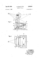
- FIG. 1 is a schematic elevation of a weighing scale of our invention as it appears when a customer looks toward the rear thereof;
- FIG. 2 is a schematic partly sectional side elevation taken along line 2-2 of FIG. 1 in the direction of the arrows; 5
- FIG. 3 is a schematic sectional side elevation taken along line 33 of FIG. 1 in the direction of the arrows;
- FIG. 4 is a schematic top plan view of the scale of FIGS. 1-3.
- the weighing scale illustrated therein includes a hollow housing 1 of substantially block-shaped configuration which has a hollow lower portion housing a weighing means which includes a transversely extending beam 2 which supports the loadcarrying means 3 provided in the illustrated example with an outer pan 18 for receiving the load which is to be weighed.
- This load-carrying means 3 is movable in a known way through openings in a forward top wall portion of the lower part of the housing 1.
- the weighing lever or beam 2 of the weighing means is situated within the lower portion of the housing 1 and carries on a first extension a counterweight 4 as well as on a second beam extension weight indicator 6 in the form of a transparent member having weight graduations thereon and carried by a rear portion of the beam 2 which is situated beneath a hollow column 5 of the housing 1, this hollow column 5 extending upwardly from and communicating with the interior of the lower hollow portion of the housing 1.
- a load is placed in the pan 18 it is possible for the weighing lever 2 to swing in a counter-clockwise direction, as viewed in FIG. 2, so as to displace the indicator 6 up to the position 7 where .it extends into the hollow interior of the column 5.
- An image of part of the indicator 6 is transmitted by an optical means to an indicating means 15 which includes a matted or frosted glass plate 15a onto which an image of part of the indicator 6 is projected.
- This optical means includes a lamp 8 which is situated within the housing 1 (FIG. 1) and which directs light to the reflectors 9 and 10 and then through a condenser 11 and objective 12 to an additional reflector the'imagempwardly' through a transparent portion of'the' 13 which directs top wall of the lower housing part up to the right portion of the indicating means 15, as viewed in FIG. 1.
- the weighing lever 2 is in addition fixed with a lever arm 16 of the weighing means, this lever arm 16 serving to guide the load-carrying means 3, 18 for movement,
- lever arm 16 is pivotally connected with a link 17 whose end distant from the arm 16 is pivoted to a stationary bracket, as is apparent from the upper right-portion of FIG. 1 and the upper portion of 'FIG. 2. 'It will be noted that this arm 16 extends upwardly along the hollow interior of the column substantially parallel to the axis of the latter.
- the link 17 is situated'within the hollow interior of the column 5 "at the upper end thereof. Also, there is situated within 'the hollow column 5 a damping means 19 such as an oil type of shock absorber which reduces the vibrations of 'the pan 18.
- the weighing lever 2 includes an extension 2a (FIG. 3)
- a guide rod 20 extends alongthe hollow interior of the other column 21 of the housing in a direction substantially parallel thereto, and this guide rod 20 forms part of a follower mechanism for following and thus scanning the position of the weighing means, and more particularly the position of the extension 2a of the beam 2.
- the guide rod 20 carries an arm 22 on which is situated “an adjustable scanning pin 23 which, by a cable 24 which is guided around suitable pulleys, is connected with 'a'nmit price adjusting mechanism 25 which sets the device to provide the price for the weight of the load according to a give price per unit of weight.
- the unit price which is adjusted in a known way and which may indicate i the" cost per kilogram, for example, can be read at the unit price indicator wheel 33 which has a pair of opposed portions visible at the front and rear of the column 21 so as to indicate both to the operator and to the cus tomer the price per unit of weight for which the device 25 has been initially set.
- this hollow column 21 guides not only the rod and the guiding structure therefor, but also structures such as the unit price indicating'scale' 33, the unit price setting structure 25, and
- the indicating means -15 which is formed in part by the matted glass plate 15a also includes reflectors 15b for providing forwardly and rearwardly directed images of the weightand cost of the load carried by the loadcarrying means 3, 18.
- This indicating means 15 is carried by the hollow columns 5 and 21 of the housing at an portion extending upwardly and rearwardly from the forward portion of the top wall into the space between .the columns 5 and 21.
- the extension 2a of the beam 2 will assume a predetermined angular-position, in accordance with the weight of the ,load; carried by thepan 18, and is then clamped in this position by an unillustrated known mechanism which is not further described.
- the guide rod 20 of the follower ,mechanism is driven in a known way to follow the posi tion of the extension 2a and displaces the arm 22 until the scanning pin 23 engages and'is stoppedb'y the extension 2a, so that in this way the follower means will assume a position determined by the position of the extension 2a.
- the price indicator 27 is brought into a position for properly indicating the cost of theload carried by the pan 18.
- the lamp 8 directs light also to a pair of reflectors 28 and 29 which direct the light through a condenser 30 and an objective 31 where it is received by the reflector 32 which directs the image of the pirce upwardly through a second transparent part of the top wall of the lower portion of the housing to the indicating means 15.
- the price indicator 27 which is transparent is situated between the condenser 30 and the objective 31, as indicated schematically in FIG. 1, and of course the indicator 6 shown in FIG. 2 is situated between the condenser 11 and objective 12 of the other optical system, as is also indicated schematically in FIG. 1.
- the primary advantage of the invention resides in the fact that essential components of the weighing means, such as the guide rod 20, the lever arm 16 and the indicator 6 are situated within or are movable into and out of the hollow columns 5 and 21. In this way the housing of the scale can be made correspondingly smaller and the pan 18 itself can be situated at a relatively low elevation, rendering the operations extremely convenient to carry out.
- a housing having a hollow lower portion and a pair of spaced upstanding hollow columns extending upwardly from and communicating with the interior of said lower housing portion, loadcarrying means situated over said lower portion of said housing for carrying a load which is to be weighed, weighing means mounted in said housing and operatively connected to said load-carrying means for weighing a load carried thereby, said Weighing means including a follower mechanism for following the position of a weighing member of said weighing means, and said follower mechanism including an elongated guide rod extending along the interior of one of said columns in a direction substantially parallel thereto, and said weighing means further including an elongated guide rod of the follower mechanism extending along the interior of the other of said columns in a direction substantially parallel thereto, and indicating means carried by said columns at an elevation spaced above said lower portion of said housing for indicating information such as the weight and price of a load carried by said load-carrying means, whereby the load-carrying means is visible from all sides
- said indicating means provides an optical image of information such as the weight and price of a load carried by said load carrying means, said housing having beneath said indicating means a transparent wall portion, and projecting means situated within said housing for projecting upwardly through said transparent wall portion to said indicating means an image to be received thereby.
- said weigh ing means includes a swingable beam carrying a counterweight and having a portion situated beneath one of said hollow columns, a transparent indicator carried by said portion of said beam and swingable into and out of said one column during swinging of said beam, and optical means coacting with said transparent indicator for optically transmitting an image of a portion thereof to said indicating means.
Landscapes
- Physics & Mathematics (AREA)
- General Physics & Mathematics (AREA)
- Cash Registers Or Receiving Machines (AREA)
- Control Of Vending Devices And Auxiliary Devices For Vending Devices (AREA)
Applications Claiming Priority (1)
| Application Number | Priority Date | Filing Date | Title |
|---|---|---|---|
| DEB0090185 | 1966-12-07 |
Publications (1)
| Publication Number | Publication Date |
|---|---|
| US3516507A true US3516507A (en) | 1970-06-23 |
Family
ID=6985153
Family Applications (1)
| Application Number | Title | Priority Date | Filing Date |
|---|---|---|---|
| US688935A Expired - Lifetime US3516507A (en) | 1966-12-07 | 1967-12-07 | Weighing scales |
Country Status (8)
| Country | Link |
|---|---|
| US (1) | US3516507A (de) |
| AT (1) | AT282988B (de) |
| BE (1) | BE707630A (de) |
| CH (1) | CH465255A (de) |
| DE (1) | DE1549154B1 (de) |
| GB (1) | GB1173058A (de) |
| NL (1) | NL6716308A (de) |
| SE (1) | SE337943B (de) |
Cited By (4)
| Publication number | Priority date | Publication date | Assignee | Title |
|---|---|---|---|---|
| USD260377S (en) | 1979-08-30 | 1981-08-25 | Reliance Electric Co. | Weight scale |
| USD261241S (en) | 1979-08-30 | 1981-10-13 | Reliance Electric Co. | Scale |
| US20120111643A1 (en) * | 2010-11-05 | 2012-05-10 | Ralf Lindner | Method and apparatus for weighing a person |
| CN107870026A (zh) * | 2017-09-04 | 2018-04-03 | 东莞技研新阳电子有限公司 | 细长物料称重系统 |
Citations (3)
| Publication number | Priority date | Publication date | Assignee | Title |
|---|---|---|---|---|
| US1213296A (en) * | 1913-02-08 | 1917-01-23 | Strubler Computing Scale Company | Computing scale. |
| GB332141A (de) * | 1929-07-19 | 1930-07-17 | N.V. Maatschappij Tot Vervaardiging Van Snijmachines | |
| FR1342658A (fr) * | 1963-01-08 | 1963-11-08 | Bizerba Werke Kraut Kg Wilh | Balance, en particulier de comptoir |
Family Cites Families (2)
| Publication number | Priority date | Publication date | Assignee | Title |
|---|---|---|---|---|
| DE525774C (de) * | 1931-05-28 | Naamlooze Vennootschap Mij Tot | Zylinderwaage | |
| FR1179676A (fr) * | 1957-07-22 | 1959-05-27 | Lutrana Sa | Appareil de pesage à système pendulaire |
-
1966
- 1966-12-07 DE DE19661549154 patent/DE1549154B1/de active Pending
-
1967
- 1967-11-30 CH CH1683767A patent/CH465255A/de unknown
- 1967-11-30 NL NL6716308A patent/NL6716308A/xx unknown
- 1967-12-05 GB GB55265/67A patent/GB1173058A/en not_active Expired
- 1967-12-06 SE SE16775/67A patent/SE337943B/xx unknown
- 1967-12-06 BE BE707630D patent/BE707630A/xx unknown
- 1967-12-06 AT AT1104867A patent/AT282988B/de active
- 1967-12-07 US US688935A patent/US3516507A/en not_active Expired - Lifetime
Patent Citations (3)
| Publication number | Priority date | Publication date | Assignee | Title |
|---|---|---|---|---|
| US1213296A (en) * | 1913-02-08 | 1917-01-23 | Strubler Computing Scale Company | Computing scale. |
| GB332141A (de) * | 1929-07-19 | 1930-07-17 | N.V. Maatschappij Tot Vervaardiging Van Snijmachines | |
| FR1342658A (fr) * | 1963-01-08 | 1963-11-08 | Bizerba Werke Kraut Kg Wilh | Balance, en particulier de comptoir |
Cited By (4)
| Publication number | Priority date | Publication date | Assignee | Title |
|---|---|---|---|---|
| USD260377S (en) | 1979-08-30 | 1981-08-25 | Reliance Electric Co. | Weight scale |
| USD261241S (en) | 1979-08-30 | 1981-10-13 | Reliance Electric Co. | Scale |
| US20120111643A1 (en) * | 2010-11-05 | 2012-05-10 | Ralf Lindner | Method and apparatus for weighing a person |
| CN107870026A (zh) * | 2017-09-04 | 2018-04-03 | 东莞技研新阳电子有限公司 | 细长物料称重系统 |
Also Published As
| Publication number | Publication date |
|---|---|
| DE1549154B1 (de) | 1972-03-09 |
| BE707630A (de) | 1968-04-16 |
| AT282988B (de) | 1970-07-27 |
| NL6716308A (de) | 1968-06-10 |
| GB1173058A (en) | 1969-12-03 |
| CH465255A (de) | 1968-11-15 |
| SE337943B (de) | 1971-08-23 |
Similar Documents
| Publication | Publication Date | Title |
|---|---|---|
| US2676515A (en) | Projecting pressure indicating instrument | |
| US3130802A (en) | Condition responsive devices | |
| US2244523A (en) | Indicating mechanism for weighing scales | |
| US3189111A (en) | Optical indicator balance with fine and coarse indicator scales | |
| US3463258A (en) | Precision balance | |
| ES433904A1 (es) | Balanza para personas perfeccionada. | |
| US2937862A (en) | Weighing scale | |
| US1502443A (en) | Automatic scale | |
| US1567224A (en) | Weighing implement the deflection of which is made visible or enlarged by optical means | |
| US2217244A (en) | Weighing scale | |
| US2570621A (en) | Indication projector for weighing scales | |
| US2302402A (en) | Weighing scale | |
| US3074496A (en) | Weighing scale | |
| US1993592A (en) | Weighing scale | |
| US3941466A (en) | Vernier carriage control | |
| USRE22297E (en) | Weighing scale | |
| US3602325A (en) | Weighing apparatus | |
| US2348374A (en) | Weighing scale | |
| US3461987A (en) | Precision balance | |
| US2068390A (en) | Indicator for weighing scales | |
| US2613926A (en) | Precision weighing balance | |
| US1784046A (en) | Metroscopic force-measuring instrument | |
| US2378274A (en) | Weighing scale | |
| US3515231A (en) | Price-indicating weighing scale | |
| US2277957A (en) | Weighing scale |