US3546403A - Motion picture apparatus with improved impulse transmitter contact structure - Google Patents
Motion picture apparatus with improved impulse transmitter contact structure Download PDFInfo
- Publication number
- US3546403A US3546403A US709005A US3546403DA US3546403A US 3546403 A US3546403 A US 3546403A US 709005 A US709005 A US 709005A US 3546403D A US3546403D A US 3546403DA US 3546403 A US3546403 A US 3546403A
- Authority
- US
- United States
- Prior art keywords
- transmitter
- impulse
- contact
- motion picture
- contacts
- Prior art date
- Legal status (The legal status is an assumption and is not a legal conclusion. Google has not performed a legal analysis and makes no representation as to the accuracy of the status listed.)
- Expired - Lifetime
Links
- 230000033001 locomotion Effects 0.000 title description 27
- 239000004020 conductor Substances 0.000 description 24
- 238000000034 method Methods 0.000 description 6
- 230000001360 synchronised effect Effects 0.000 description 3
- 230000005540 biological transmission Effects 0.000 description 2
- 230000007704 transition Effects 0.000 description 2
- 235000014748 Amaranthus tricolor Nutrition 0.000 description 1
- 244000024893 Amaranthus tricolor Species 0.000 description 1
- 235000010725 Vigna aconitifolia Nutrition 0.000 description 1
- 239000002775 capsule Substances 0.000 description 1
- 238000006243 chemical reaction Methods 0.000 description 1
- 238000010276 construction Methods 0.000 description 1
- 238000005286 illumination Methods 0.000 description 1
Images


Classifications
-
- H—ELECTRICITY
- H01—ELECTRIC ELEMENTS
- H01H—ELECTRIC SWITCHES; RELAYS; SELECTORS; EMERGENCY PROTECTIVE DEVICES
- H01H19/00—Switches operated by an operating part which is rotatable about a longitudinal axis thereof and which is acted upon directly by a solid body external to the switch, e.g. by a hand
- H01H19/54—Switches operated by an operating part which is rotatable about a longitudinal axis thereof and which is acted upon directly by a solid body external to the switch, e.g. by a hand the operating part having at least five or an unspecified number of operative positions
- H01H19/56—Angularly-movable actuating part carrying contacts, e.g. drum switch
- H01H19/58—Angularly-movable actuating part carrying contacts, e.g. drum switch having only axial contact pressure, e.g. disc switch, wafer switch
- H01H19/585—Angularly-movable actuating part carrying contacts, e.g. drum switch having only axial contact pressure, e.g. disc switch, wafer switch provided with printed circuit contacts
-
- G—PHYSICS
- G03—PHOTOGRAPHY; CINEMATOGRAPHY; ANALOGOUS TECHNIQUES USING WAVES OTHER THAN OPTICAL WAVES; ELECTROGRAPHY; HOLOGRAPHY
- G03B—APPARATUS OR ARRANGEMENTS FOR TAKING PHOTOGRAPHS OR FOR PROJECTING OR VIEWING THEM; APPARATUS OR ARRANGEMENTS EMPLOYING ANALOGOUS TECHNIQUES USING WAVES OTHER THAN OPTICAL WAVES; ACCESSORIES THEREFOR
- G03B19/00—Cameras
- G03B19/18—Motion-picture cameras
-
- G—PHYSICS
- G03—PHOTOGRAPHY; CINEMATOGRAPHY; ANALOGOUS TECHNIQUES USING WAVES OTHER THAN OPTICAL WAVES; ELECTROGRAPHY; HOLOGRAPHY
- G03B—APPARATUS OR ARRANGEMENTS FOR TAKING PHOTOGRAPHS OR FOR PROJECTING OR VIEWING THEM; APPARATUS OR ARRANGEMENTS EMPLOYING ANALOGOUS TECHNIQUES USING WAVES OTHER THAN OPTICAL WAVES; ACCESSORIES THEREFOR
- G03B31/00—Associated working of cameras or projectors with sound-recording or sound-reproducing means
- G03B31/04—Associated working of cameras or projectors with sound-recording or sound-reproducing means in which sound track is not on, but is synchronised with, a moving-picture film
-
- G—PHYSICS
- G03—PHOTOGRAPHY; CINEMATOGRAPHY; ANALOGOUS TECHNIQUES USING WAVES OTHER THAN OPTICAL WAVES; ELECTROGRAPHY; HOLOGRAPHY
- G03G—ELECTROGRAPHY; ELECTROPHOTOGRAPHY; MAGNETOGRAPHY
- G03G9/00—Developers
- G03G9/06—Developers the developer being electrolytic
-
- H—ELECTRICITY
- H01—ELECTRIC ELEMENTS
- H01H—ELECTRIC SWITCHES; RELAYS; SELECTORS; EMERGENCY PROTECTIVE DEVICES
- H01H19/00—Switches operated by an operating part which is rotatable about a longitudinal axis thereof and which is acted upon directly by a solid body external to the switch, e.g. by a hand
- H01H19/005—Electromechanical pulse generators
-
- H—ELECTRICITY
- H01—ELECTRIC ELEMENTS
- H01H—ELECTRIC SWITCHES; RELAYS; SELECTORS; EMERGENCY PROTECTIVE DEVICES
- H01H3/00—Mechanisms for operating contacts
- H01H3/004—Mechanisms for operating contacts for operating contacts periodically
-
- H—ELECTRICITY
- H01—ELECTRIC ELEMENTS
- H01H—ELECTRIC SWITCHES; RELAYS; SELECTORS; EMERGENCY PROTECTIVE DEVICES
- H01H19/00—Switches operated by an operating part which is rotatable about a longitudinal axis thereof and which is acted upon directly by a solid body external to the switch, e.g. by a hand
- H01H19/02—Details
- H01H19/10—Movable parts; Contacts mounted thereon
- H01H19/12—Contact arrangements for providing make-before-break operation, e.g. for on-load tap-changing
Definitions
- the impulse transmitter is adapted to be used selecg 7D" in tively with any one of a number of ditferent synchronizing 8 W a Figs methods and is provided with a slidable contact member and a [52] U.S.CI. 200/24, number of groups of transmitter contacts which are spaced 340/356 and offset from each other in the direction of movement of [51] Int. Cl. H0lh 39/00 said slidable contact member.
- This slidable contact member is [50] Field Search 200/1 1(A), adapted to be alternately connected to a current supply conll(D), 14, 25, 24, 153, 16(X), 51, 61.45; ductor and selectively to at least one of a plurality of electric 340/345, 354, 357, 364 conductors which transmit the synchronizing impulses.
- Known motion picture apparatus of this kind are constructed to transmit synchro-impulse sequences of various patterns. For example, a sequence of one impulse perpicture is employed for the flash-illumination of a films'cene to .be shot, or for the flash operation of a motion picture projector. Synchro-impulse sequences are also used for the control of a synchronized operation between a motion picture apparatus (camera and projectorland a sound apparatus as it is required for a sound film recording and reproduction in the two-tape method.
- a motion picture apparatus camera and projectorland a sound apparatus as it is required for a sound film recording and reproduction in the two-tape method.
- the impulse frequency varies between three impulses per picture and one impulse each to four pictures.
- the transmission of the impulses is effected by way of a single electric conductor of by a plurality of such conductors, for instance three.
- the synchroimpulse transmitter acts as a'three phase current generator for a synchronous motor driving the sound apparatus. For each of these possibilities a separate impulse transmitter is provided.
- the invention has .as its object to create a synchro-impulse transmitter which is equally efficient for a variety of synchronizing jobs and methods. Its construction is to be as simple as possible and such that a conversion from one to another method and from one to another impulse sequence, respectively, does no longer require any adjustment to be made in'the apparatus.
- the synchro-impulse transmitter in a motion picture apparatus of the kind mentioned is provided with groups of transmitter contacts which are electrically connected with each other, whereby the transmitter contacts for the purpose of being alternately connected to a current conductor are positioned offset with respect to each other in the direction of movement of a slidable contact member and are adapted to be selectively connected to one or more electrical conductors by means of whichthe synchro-impulses are activated.
- At least one transmitter contact of one of the groups is adapted to be electrically separable by circuit means.
- the synchro-impulse transmitter is provided with three groups each comprising four transmitter contacts in circular arrangement'and a current supply contact in the center of this circle, whereby the transmitter contact groups are so spaced with respect to each other that 12 transmitter contacts are evenly distributed over a perimeter of 360One of the three groups of transmitter contacts may be adapted to be electrically separated by circuit means into individual contacts.
- a commutator which may be arranged at the motion picture apparatus, at the cable connecting the motion picture apparatus and the sound apparatus, or on thesound apparatus.
- a commutator may also serve connecting cords, the plugs of which either combine in themselves the electric cables coming from the transmitter contacts in accordance with the selection made, conduct them on separately or terminate them.
- This impulse transmitter device may according to the invention be accommodated to form a structural unit which is attachable to the apparatus housing from the outside'and which through an opening in the wall of the apparatus housing may be connected to the film drive mechanism of the apparatus,
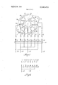
- FIG. I is a diagrammatic view of the contact, plate according to the-invention including itsconnections toconnector sleeves provided on the apparatus and a connecting plug for converting the synchro-impulse transmitter into a three phase current generator;
- FIG. 2 illustrates diagrammatically a' plug connection by which the synchro-irnpulse transmitter transmits one synchronizing impulse each at a rate of four pictures;
- FIG. 3 illustrates diagrammatically a plug connection by which the synchro-impulse' transmitter transmits one synchronizing impulse at each picture
- FIG; 4 illustrates diagrammatically a plug connection by which the synchro-impulse transmitter transmits one synchronizing impulse each at two pictures;
- FIG. 5 is a sectional view of a synchro-impulse transmitter device according to the invention.
- FIG. 6 is a longitudinal sectional view of a synchro-impulse transmitter according to FIG. 5;
- FIG. 7 is a diagrammatic view of a disk spring serving as a slidable contact member.
- connecter sleevesI, 2 and 3, and 5, 6, 7 and 8, respectively, are connected by electric cables to three groups 9a, 9b, 9c of transmitter contacts of a contact plate 10.
- An electric cable extends from the connecting sleeve 4 to a centrally located current supply contact 23 of the contact plate 10.
- a connecting plug 47 having mounted thereon the plugs 11 to 18.
- the connecting plugs 12, 13, I5 and 16 are connected to an impulse conductor 19
- the connecting plugs II and 17 are connected to an'impulse conductor 20
- the connecting plug 18 is connected to an impulse conductor 21.
- the connecting plug 14 is connected to a current supply conductor 22.
- a contact bar 24 represents a rotating contact member capsule of connecting the individual transmitter contacts of the groups 911, 9b and 9c successively with the current supply contact 23.
- the connecting sleeves l to 8 are coupled with a connecting plug of which solely the connecting pin 14 is connected to the current supply conductor 22 and the connecting pins 15 to 17 are jointly connected to the impulse conductor 20, then the sound apparatus receives only one synchronizing impulse during one complete revolution of the contact bar 24. This occurs as long as the contact bar 24 connects the current supply contact 23 with the transmitter contacts of the groups 9a and 9b which are connected to the sleeves 5 and 7.
- This embodiment then, produces one synchronizing impulse each to four pictures.
- This type of control is provided in so-called unit tone systems.
- the connecting pins 12, 13, 15 and 16 are connected to the impulse conductor 20.
- the electric current conducted by the current supply conductor 22 to the connecting pin M, the connecting sleeve d, the current supply contact 23 and the contact bar 24 transmits synchronizing impulses to the impulse conductor 20 and from there to the sound apparatus only upon contacting transmitter contacts of the group 9b.
- This circuit therefore, produces a sequence of one impulse per picture. This is suitable, for example, for sound picture shooting, for flash picture series or for counter control.
- the connecting plug closes the impulse circuit with respect to the impulse conductor 20 and therewith to the sound apparatus solely by means of the connecting pins 13 and 16 and the connecting" pin 1d including the current supply conductor 22.
- the rotating contact bar 24 is restricted to transmitting an impulse only upon contacting the transmitter contacts of the group 9b which are connected to the connecting sleeves 3 and 6.
- this rate is suitable for sound motion pictures or, for instance, for the control of the counting device.
- the contact plate 10 illustrated in FIG. 1 is mounted in a housing 25 which simultaneously serves as a socket member 26 provided with the connecter sleeves 1 to 8.
- This housing 25 (FIG. isattachable to a wall 27 of the housing of a motion picture apparatus. Between the housing wall 27 and the housing 25 is inserted a plate 28 carrying a bearing sleeve 29 and a bearing pin 30. Screws 31 (FIG. 6) fasten the-plate 28 to the housing 25 and the latter together with the plate 28 is in turn attached to the housing wall 27 by screws 32.
- the bushing 29 projects through an opening 33 provided in the housing wall 27 into the housing of the motion picture apparatus.
- the bushing 29 supports a shaft 34 one end of which, namely that end which projects into the housing 25, is attached to a gear wheel 35.
- the other end of the shaft 34 carries a pinion 36 the teeth of which mesh with the teeth of a friction wheel 37 which is mounted on a pin 38 of the motion picture apparatus.
- the gear wheel 35 engages the teeth of a gear wheel 39 which is supported by the bearing pin 30.
- the bearing pin 30 and hence the gear wheel 39 are disposed opposite the contact plate in such a manner that the center pf the current supply contact 23 is located on the axis of rotation of the gear wheel 39.
- To one face of the gear wheel 39 is attached a disk spring 40 (FIG.
- the transmission ratio is so selected that the contact bar 24, which in the embodiment illustrated in FIGS. 5 to 7 is formed by the dislt spring 40, performs one complete revolution while the film drive mechanism advances the film by four pictures.
- the contact bar 24 which in the embodiment illustrated in FIGS. 5 to 7 is formed by the dislt spring 40, performs one complete revolution while the film drive mechanism advances the film by four pictures.
- any one of the impulse sequences illustrated in FIGS. 1 to 4 may be produced.
- the contact surfaces on the contact plate 10 remain firmly connected with the connecting sleeves l to 8 associated with them.
- a transmitter for synchro-impulses for motion picture apparatus including a film drive mechanism which also drives said transmitter, wherein the improvement comprises a contact plate with a centrally disposed contact member connected to a current supply and a series of 12 transmitter contacts arranged closely adjacent to each other and concentrically around said central contact member, means including electrical conductors for selectively connecting said transmitter contacts with aslidable contact member which is in constantelectrical connection with said centrally disposed contact member, said 12 transmitter contacts being arranged in three symmetrically disposed groups, each having four contacts which are electrically connected with each other, whereby in each contact in each group is placed between two contacts of the other two groups, means for rotating said slidable contact member by said drive mechanism in such a manner that when said slidable contact member has moved once over all said transmitter contacts said drive mechanism has advanced the film a distance equal to four picture frames.
- a transmitter for synchro-impulses for motion picture apparatus including circuit means for electrically disconnecting at least one of said transmitter contacts.
- a transmitter for synchro-inpulses for motion picture apparatus according to claim vl including circuit. means for separating one of said three groups of transmitter contacts into individual contacts.
- a transmitter for synchro-impulses for motion picture apparatus in which said slidable contact 'member for effecting the selective connection of said transmitter contacts to a number of said electrical conductors is arranged on the motion picture apparatus.
- a transmitter for synchro-impulses for motion picture apparatus in which said slidable contact member for effecting the selective connection of said transmitter contacts to a number of electrical conductors is arranged on the connecting cable between the motion picture apparatus and the sound apparatus.
- a transmitter for synchro-impulses for motion picture apparatus in which said selective connection of said transmitter contacts to a number of electrical conductors is effected by a number of connecting cables provided with plugs, said plugs unite the electric cables coming from the transmitter contacts in accordance with the selection made.
- a transmitter for synchro-implulses for motion picture apparatus in which said synchro-impulse transmitting device comprises a structural unit which is attachable to the apparatus housing (27) from the outside and which through an opening (33) in the wall of said apparatus housing is connected to the film drive mechanism-of said apparatus, said opening being covered by said impulse transmitter unit itself.
- a transmitter for synchro-impulses for motion picture apparatus including a disk spring arranged opposite said contact plate and rotatable by said film drive mechanism, said disk spring serving as said slidable contact member which successively connects the current supply contact and the transmitter contacts with each other.
Landscapes
- Physics & Mathematics (AREA)
- General Physics & Mathematics (AREA)
- Transmission And Conversion Of Sensor Element Output (AREA)
- Endoscopes (AREA)
Applications Claiming Priority (1)
| Application Number | Priority Date | Filing Date | Title |
|---|---|---|---|
| DEZ0012724 | 1967-03-04 |
Publications (1)
| Publication Number | Publication Date |
|---|---|
| US3546403A true US3546403A (en) | 1970-12-08 |
Family
ID=7622730
Family Applications (1)
| Application Number | Title | Priority Date | Filing Date |
|---|---|---|---|
| US709005A Expired - Lifetime US3546403A (en) | 1967-03-04 | 1968-02-28 | Motion picture apparatus with improved impulse transmitter contact structure |
Country Status (5)
| Country | Link |
|---|---|
| US (1) | US3546403A (de) |
| AT (1) | AT276091B (de) |
| CH (1) | CH458055A (de) |
| DE (1) | DE1522347A1 (de) |
| FR (1) | FR1557255A (de) |
Cited By (2)
| Publication number | Priority date | Publication date | Assignee | Title |
|---|---|---|---|---|
| US4021023A (en) * | 1975-09-29 | 1977-05-03 | Berg Joseph A | Automatic agitator for film development |
| US20080087529A1 (en) * | 2006-10-11 | 2008-04-17 | Hosiden Corporation | Rotary type pulse switch |
Families Citing this family (1)
| Publication number | Priority date | Publication date | Assignee | Title |
|---|---|---|---|---|
| FR2738665B1 (fr) * | 1995-09-08 | 1997-10-17 | Valeo Electronique | Commutateur electrique pour tableau de commande, notamment de dispositif de chauffage, ventilation et/ou climatisation de vehicule automobile |
-
1967
- 1967-03-04 DE DE19671522347 patent/DE1522347A1/de active Pending
- 1967-11-17 CH CH1613067A patent/CH458055A/de unknown
- 1967-12-19 AT AT1144067A patent/AT276091B/de active
-
1968
- 1968-02-28 US US709005A patent/US3546403A/en not_active Expired - Lifetime
- 1968-03-01 FR FR1557255D patent/FR1557255A/fr not_active Expired
Cited By (3)
| Publication number | Priority date | Publication date | Assignee | Title |
|---|---|---|---|---|
| US4021023A (en) * | 1975-09-29 | 1977-05-03 | Berg Joseph A | Automatic agitator for film development |
| US20080087529A1 (en) * | 2006-10-11 | 2008-04-17 | Hosiden Corporation | Rotary type pulse switch |
| US7652217B2 (en) | 2006-10-11 | 2010-01-26 | Hosiden Corporation | Rotary type pulse switch |
Also Published As
| Publication number | Publication date |
|---|---|
| CH458055A (de) | 1968-06-15 |
| FR1557255A (de) | 1969-02-14 |
| AT276091B (de) | 1969-11-10 |
| DE1522347A1 (de) | 1969-07-24 |
Similar Documents
| Publication | Publication Date | Title |
|---|---|---|
| GB1429680A (en) | Electrical switch assemblies | |
| US2539556A (en) | Variable delay speech privacy system | |
| US3122054A (en) | Audiovisual projection system | |
| US3204236A (en) | Personnel locating device | |
| US2394361A (en) | Synchronizing device | |
| GB968538A (en) | Push button type telephone calling device | |
| US2427621A (en) | Remote-control system | |
| CN215835472U (zh) | 一种物体外观全景拍摄的拍摄角度精确控制装置 | |
| US2825768A (en) | Commutating devices | |
| US3644689A (en) | Electric signaling device for alarm clocks | |
| US2380542A (en) | Synchronizing and phasing system | |
| US2488228A (en) | Firing switch for rocket launchers | |
| JPH06104061A (ja) | 印刷機における回転軸への伝達装置 | |
| US3534543A (en) | Electric signaling device for alarm clocks | |
| US3752943A (en) | Multiple memo timing device with adjustable pin conductors | |
| US2233113A (en) | Radio receiving apparatus | |
| US3120655A (en) | Motion and direction sensing device | |
| US2406347A (en) | Speech privacy communication | |
| US2445820A (en) | Motor control switching system and device therefor | |
| US2949596A (en) | Electrical connecting device | |
| US4066963A (en) | Synchronization system of the cine-projector with the sound tape reproducer | |
| US993610A (en) | Synchronizing device. | |
| US2585839A (en) | Time interrupter for electric apparatus | |
| US2399956A (en) | Electric remote-control system | |
| US1931099A (en) | Regenerative repeater |