US3552424A - Floating lift station - Google Patents
Floating lift station Download PDFInfo
- Publication number
- US3552424A US3552424A US3552424DA US3552424A US 3552424 A US3552424 A US 3552424A US 3552424D A US3552424D A US 3552424DA US 3552424 A US3552424 A US 3552424A
- Authority
- US
- United States
- Prior art keywords
- sewage
- holding tank
- conduit
- tank
- floating
- Prior art date
- Legal status (The legal status is an assumption and is not a legal conclusion. Google has not performed a legal analysis and makes no representation as to the accuracy of the status listed.)
- Expired - Lifetime
Links
- 239000010865 sewage Substances 0.000 claims abstract description 63
- 230000005484 gravity Effects 0.000 claims abstract description 9
- 238000010276 construction Methods 0.000 description 3
- XLYOFNOQVPJJNP-UHFFFAOYSA-N water Substances O XLYOFNOQVPJJNP-UHFFFAOYSA-N 0.000 description 2
- 241001492414 Marina Species 0.000 description 1
- 229910000831 Steel Inorganic materials 0.000 description 1
- 230000002939 deleterious effect Effects 0.000 description 1
- 238000006073 displacement reaction Methods 0.000 description 1
- 239000011152 fibreglass Substances 0.000 description 1
- 239000000463 material Substances 0.000 description 1
- 239000002184 metal Substances 0.000 description 1
- 239000007787 solid Substances 0.000 description 1
- 239000010959 steel Substances 0.000 description 1
Images
Classifications
-
- E—FIXED CONSTRUCTIONS
- E02—HYDRAULIC ENGINEERING; FOUNDATIONS; SOIL SHIFTING
- E02B—HYDRAULIC ENGINEERING
- E02B3/00—Engineering works in connection with control or use of streams, rivers, coasts, or other marine sites; Sealings or joints for engineering works in general
- E02B3/04—Structures or apparatus for, or methods of, protecting banks, coasts, or harbours
- E02B3/06—Moles; Piers; Quays; Quay walls; Groynes; Breakwaters ; Wave dissipating walls; Quay equipment
- E02B3/062—Constructions floating in operational condition, e.g. breakwaters or wave dissipating walls
- E02B3/064—Floating landing-stages
-
- E—FIXED CONSTRUCTIONS
- E03—WATER SUPPLY; SEWERAGE
- E03F—SEWERS; CESSPOOLS
- E03F5/00—Sewerage structures
- E03F5/22—Adaptations of pumping plants for lifting sewage
-
- Y—GENERAL TAGGING OF NEW TECHNOLOGICAL DEVELOPMENTS; GENERAL TAGGING OF CROSS-SECTIONAL TECHNOLOGIES SPANNING OVER SEVERAL SECTIONS OF THE IPC; TECHNICAL SUBJECTS COVERED BY FORMER USPC CROSS-REFERENCE ART COLLECTIONS [XRACs] AND DIGESTS
- Y10—TECHNICAL SUBJECTS COVERED BY FORMER USPC
- Y10T—TECHNICAL SUBJECTS COVERED BY FORMER US CLASSIFICATION
- Y10T137/00—Fluid handling
- Y10T137/6851—With casing, support, protector or static constructional installations
Definitions
- the present invention provides a sewage disposal system for a floating wharf structure which allows accessthereto from any-of a plurality of boat slips associated with the wharf structure.
- a sewer system for a floating wharfis-provided comprising: a main sewage conduitat a first level; a
- The's'e'wage feeding means comprises a feed conduit having an-intake port and an exhaust, the intake port beingat a level higherthan the sewage in the holding tank.
- Means are provided for connecting'the exhaust of the feed conduit to the holding tank'whereby sewage introduced into the feed conduitis gravity fed to the holding tank.
- An intake port is provided at each of ajpluralityof boat slips, each such intake port being at a level higher than the sewage in the holding tank, toreceive sewage from said boat slips and gravity feed it to the holding tank.
- the holdingtank is secured in a substantially fixed lateral position with respect to the'wharfbutis'allowedto moveverti cally.
- the holding tank is slidably'disposedwn rigid means extending downwardly from the wharf-structure, and means are included for limiting the extent-of-its downward movement.
- the holding tank includes intake and :exhaust p'ons'forconnection to theexhau'stof the feed; conduit and to the main sewage conduit, respectively, and is connected of the headwalk l0 and constitute a floating wharf structure.
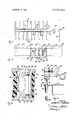
- the structure is supported on pontoons 18. (FIG. 2) and is connected to a land structure 20 by means of a ramp 22 extending from one end of the wharf structure to the land structure 20.
- the sewer system in accordance with this invention is shown by dashed lines in FIG. 1 and includes a lift station 24 into which sewage is fed by means-of a feed conduit 26 extending lengthwise of the headwalk 10 which, in turn, is fed by a plurality of branch conduits 28.
- the branch conduits are disposed so that each boat slip 16 has a branch conduit 28 associated therewith. Sewage is gravity fed into the lift station and, as hereinafter described, is then pumped into a main sewage conduit 30 which leads into the main sewer line as indicated by the arrow 32, Inoperation, a boater connects the disposal system of hisboat into the branch sewer conduit 28 located at the slip in whichhis boat is docked.
- FIG. 2 an elevational view of the lift station 24 and details of construction of the'wharf structure are shown.
- the headwalk 10 is seen to overlie a plurality of pontoons 18 (of which only two are shown) which are interconnected by means of a deck 34 (FIG. 4 common thereto and by a pair of oppositely disposed 3 inches times 8 inches stringers 36 and 38 (FIG. 3) bridging the pontoons 18.
- the key structure in the lift station 24 is a holding tank constructed of fiberglass or other'waterproof, light but strong material.
- the'holding tank 40 is providedwith a cover 42 closely fit thereto, an intake port 44 and, in this case, a pair of exhaust ports-46 and 48.
- a relatively short length of flexible tubing 50 connects the intake port to the exhaust 52 of the feed conduit 26 noted above.
- Other relatively short lengthsof flexible tubing 54 and 56 connect the exhaust ports 46 and 48, respectively, to the main sewage conduit 30.
- a pair of submersible pumps -58 andv 60 are disposed on the bottomof the holding tank 40 .and connect respectively to the exhaust port flexible tubing sections 54 and 56, into the main sewage conduit 30.
- FIG. 1 is a plan view of a floatingwharfstrujcture utilizing a FlG.2is amelevational view ofa liftstation of thisinvention utilized in the structure' of FIG. 1 takenon-theline'2-2of FIG. 'I in the direction of the arrows; 1
- FIG. 3 is a partially cutaway,horizontabsectional* view of the lift station depicted 'inFF-IG t 2, taken-on line-343 no.2, ulcerhe direction of the'a'rrowsyand
- FIG. 4 is a broken, enlarged verticabsection viewofaportion of the wharfstructure and lift station depicted in FlG.”,2, taken on line 4-4 of FIG. 2; in the direction offthe arrows.
- FIG. l there is illustrateda floatingwharf structure, including a headwalk-l0 and a plurality of finger sections 12 connected to-the headwalk" by means 'of corner sections 14.
- the headwalklll, -finger"sections l:2'and”corner sections l4 define ajpliirality of boat slips l'6 a'longf-both sides laterally restrained so that horizontal displacement is prevented.
- FIG. 4 there is disclosed'thermanner in which theholding tank 40 isallowed to free-float, and other details of construction of the floating wharf are illustrated.
- the headwalk 34 of the floatingwharf is constructed of cast concrete andhasembeddedxtherein a pluralityxof threaded nuts, such as that shown as 62:to.enablefastening.thereat'ofthe stringer 36 by means of a bolt 64 therethrough; aplurality of-such bolts 64 are'shown in FIG; 2.
- a metal,..L'-shaped* beam 66 is; disposed 1 between thestringer 36 .an'd the side of theconcrete headwalk v34 and-serves to stronglysupport lateral guide-members68 extending downwardly therefrom,'The'horizontal, lower leg of the L-shaped beam 66 defines threaded openings therethrough aligned with apertures72.in thestringer36 for .threadably receivingandretaining therein'the threaded ends of the latera'lwguide members'v68.
- F-lG.2, .sets of threesuch guide members are disposedon-opposite-sides of the holding. tank 40.
- The'hol'ding tank 40' is provided -with a flared lip 74 which is :coex-tensive with'fthe rim.'76aofthe holding tank cover 42.An aperture '78is formed through thecoextensive lip 74 and rim"7,6and is reinforced with a short section of steel pipe 80 welded thereto.
- the holding tank 40 is disposed beneath the walkway 34 between a pair of pontoons 18, and beneath any utility lines such as shown at 84 which are supported by the pontoons 18.
- the holding tank 40 is limited in its lateral movement by means of the guide members 68.
- the guide members 68 allow the holding tank 40 to otherwise freelyfloat on the water.
- Solid ballast is provided (shown by the dashed line 86 in FIG. 2) so as to cause the holding tank 40 to float at a minimum distance below the headwalk 34.
- the walkway 10 is pitched at a small angle as a result of the weight of the gang plank 22 so that the feed conduit 26 is pitched slightly towards the lifting station 24.
- Sewage is introduced into the feed conduit 26 through a branch conduit 28 and is gravity fed, via the flexible tubing 50, into the holding tank intake port 44.
- the holding tank 40 submerges as the result of the increased ballast therein until a point is reached wherein the pumps 58 and 60 are automatically actuated.
- any means known to the art can be utilized to actuate the pumps in response to an increase of volume of sewage in the holding tanks; for example, a simple float-ball system can be utilized.
- the pumps 58 and 60 transfer the sewage from the holding tanks through its exhaust ports 46 and 48, via the respective flexible tubing sections 54 and 56, into the main sewage conduit 30 from where it travels to the land-located main sewer line. It will be seen that as the holding tank 40 is lowered and raised on the guided member 68 as a result of first filling and then emptying, n deleterious effect is manifested on the floating wharf structure since the holding tank 40 moves substantially independently of the wharf.
- a sewer system for a floating wharf comprising:
- a floating tank for holding sewage below a first level
- said transferring means comprises a pump which is automatically actuated when said sewage in said holding tank reaches a predetermined level therewithin to pump said sewage into said main sewage conduit.
- the system of claim 1 including a flexible conduit between said holding tank and said sewage feeding means and a flexible conduit between said holding tank and said main sewage conduit, whereby said holdingtank can float between predetermined limits offlexure of said conduits.
- ballast means in said holding tank for limiting the upward floating level thereof.
- said sewage feeding means comprises a feed conduit having an intake and an exhaust, said intake being at a level higher than said first level, said sewer system including means for connecting said feed conduit exhaust to said holding tank whereby sewage introduced into said feed conduit is gravity fed to said holding tank.
- said feed conduit has an intake port at each of a plurality of said boat slips for enabling said feed conduit to receive sewage therefrom, each of said intake ports being at a level higher than said first level.
- a floating lift station comprising:
Landscapes
- Engineering & Computer Science (AREA)
- General Engineering & Computer Science (AREA)
- Environmental & Geological Engineering (AREA)
- Hydrology & Water Resources (AREA)
- Public Health (AREA)
- Water Supply & Treatment (AREA)
- Health & Medical Sciences (AREA)
- Life Sciences & Earth Sciences (AREA)
- Ocean & Marine Engineering (AREA)
- Mechanical Engineering (AREA)
- Civil Engineering (AREA)
- Structural Engineering (AREA)
- Sewage (AREA)
Abstract
A sewer system for a floating wharf utilizing a floating lift station. Means are provided for gravity feeding sewage from a plurality of floating boat slips to a floating holding tank at the lift station, and means are provided for transferring sewage from the holding tank to a main sewage conduit.
Description
United States Patent 444,007 I/] 891 Monjeau Inventor Kenneth L. Thompson Huntington Beach, Calif. Appl. No. 818,658 Filed Apr. 23, 1969 Patented Jan. 5, 1971 Assignee Ye Dock Master, Inc.
a corporation of California FLOATING LIFT STATION 12 Claims, 4 Drawing Figs.
[1.8. (I 137/343, 4/10; ll4/0.5(F) Int. Cl F161 5/00 Field ofSearch 2l4/12; l|4/0.5(F),2l0/242;4/l0. 15; 137/344 References Cited UNITED STATES PATENTS Primary Examiner-Samuel Scott Atlomey-Nilsson and Robbins ABSTRACT: A sewer system for a floating wharf utilizing a floating lift station. Means are provided for gravity feeding sewage from a plurality of floating boat slips to a floating holding tank at the lift station, and means are provided for transferring sewage from the holding tank to a main sewage conduit.
sewer system of this invention;
. f 1 FLOATING LIFT STATION BACKGROUND OF THE INVENTION 1. Field of the Invention The fields of art to which the invention pertains include the field of sewerage and the field of ships, particularly floating docks therefor. g k
2. Description of the Prior Art In constructing marinas or small boat harbors it isoften desirable to utilize a floating, wharf structure which is accessible to land and has one or more fingers extending out into the body of water. At certainfacilities, it often occurs that the boater remains in a ;boat slip for an extended period of time during which time he lives on the boat. Under such circumstances, the boater requires sewage disposalfacilities and it is desirable to provide such facilities, or access to such facilities at the boat slip. However, theprovision of sewage disposal facilities on a floating wharf structure presents problems of construction which have heretofore generally limited the availability of sewage disposal facilities tononfloating structures or to limited access areas.
SUMMARY OF THE INVENTION The present invention provides a sewage disposal system for a floating wharf structure which allows accessthereto from any-of a plurality of boat slips associated with the wharf structure. In particular, a sewer system for a floating wharfis-provided, comprising: a main sewage conduitat a first level; a
floating tank for holdingsewagebelow the first level; meansfor feeding sewage from a plurality of floating boat slips to the holding tank; and means for transferring sewage from the holding tank to the main sewage conduit. The's'e'wage feeding means comprises a feed conduit having an-intake port and an exhaust, the intake port beingat a level higherthan the sewage in the holding tank. Means are provided for connecting'the exhaust of the feed conduit to the holding tank'whereby sewage introduced into the feed conduitis gravity fed to the holding tank. An intake port is provided at each of ajpluralityof boat slips, each such intake port being at a level higher than the sewage in the holding tank, toreceive sewage from said boat slips and gravity feed it to the holding tank.
The holdingtank is secured in a substantially fixed lateral position with respect to the'wharfbutis'allowedto moveverti cally. In particular, the holding tank is slidably'disposedwn rigid means extending downwardly from the wharf-structure, and means are included for limiting the extent-of-its downward movement. The holding tank includes intake and :exhaust p'ons'forconnection to theexhau'stof the feed; conduit and to the main sewage conduit, respectively, and is connected of the headwalk l0 and constitute a floating wharf structure. The structure is supported on pontoons 18. (FIG. 2) and is connected to a land structure 20 by means of a ramp 22 extending from one end of the wharf structure to the land structure 20. The sewer system in accordance with this invention is shown by dashed lines in FIG. 1 and includes a lift station 24 into which sewage is fed by means-of a feed conduit 26 extending lengthwise of the headwalk 10 which, in turn, is fed by a plurality of branch conduits 28. The branch conduits are disposed so that each boat slip 16 has a branch conduit 28 associated therewith. Sewage is gravity fed into the lift station and, as hereinafter described, is then pumped into a main sewage conduit 30 which leads into the main sewer line as indicated by the arrow 32, Inoperation, a boater connects the disposal system of hisboat into the branch sewer conduit 28 located at the slip in whichhis boat is docked. Upon disposing of his sewage, it is gravity fed via the feed conduit 26 into the lift station 24, and from there it is pumped into the main sewage conduit 30. Referring to FIG. 2, an elevational view of the lift station 24 and details of construction of the'wharf structure are shown. The headwalk 10 is seen to overlie a plurality of pontoons 18 (of which only two are shown) which are interconnected by means of a deck 34 (FIG. 4 common thereto and by a pair of oppositely disposed 3 inches times 8 inches stringers 36 and 38 (FIG. 3) bridging the pontoons 18. v
The key structure in the lift station 24 is a holding tank constructed of fiberglass or other'waterproof, light but strong material. Referring additionally to FIG. 3, the'holding tank 40 is providedwith a cover 42 closely fit thereto, an intake port 44 and, in this case, a pair of exhaust ports-46 and 48. A relatively short length of flexible tubing 50 connects the intake port to the exhaust 52 of the feed conduit 26 noted above. Other relatively short lengthsof flexible tubing 54 and 56 connect the exhaust ports 46 and 48, respectively, to the main sewage conduit 30. A pair of submersible pumps -58 andv 60 are disposed on the bottomof the holding tank 40 .and connect respectively to the exhaust port flexible tubing sections 54 and 56, into the main sewage conduit 30.
An important featureof'this invention is that, within the limits of flexure of the tubing 50,.54and 56,,the holding'tank 40 is substantially free-floating in the verticahdirection, but is th'e'retoby means of flexible condu'it whereby-the holding tank is essentially free-floatingwithin limits ofsuch flexure.
BRIEF DESCRIPTION OF THEDRAWINGS FIG. 1 is a plan view of a floatingwharfstrujcture utilizing a FlG.2is amelevational view ofa liftstation of thisinvention utilized in the structure' of FIG. 1 takenon-theline'2-2of FIG. 'I in the direction of the arrows; 1
FIG. 3 is a partially cutaway,horizontabsectional* view of the lift station depicted 'inFF-IG t 2, taken-on line-343 no.2, irithe direction of the'a'rrowsyand FIG. 4 is a broken, enlarged verticabsection viewofaportion of the wharfstructure and lift station depicted in FlG.",2, taken on line 4-4 of FIG. 2; in the direction offthe arrows.
DETAILED DESCRIPTION Referring toFlG. l, there is illustrateda floatingwharf structure, including a headwalk-l0 and a plurality of finger sections 12 connected to-the headwalk" by means 'of corner sections 14. The headwalklll, -finger"sections l:2'and"corner sections l4 define ajpliirality of boat slips l'6 a'longf-both sides laterally restrained so that horizontal displacement is prevented.
"Referringto FIG. 4, there is disclosed'thermanner in which theholding tank 40 isallowed to free-float, and other details of construction of the floating wharf are illustrated. The headwalk 34 of the floatingwharf is constructed of cast concrete andhasembeddedxtherein a pluralityxof threaded nuts, such as that shown as 62:to.enablefastening.thereat'ofthe stringer 36 by means of a bolt 64 therethrough; aplurality of-such bolts 64 are'shown in FIG; 2. A metal,..L'-shaped* beam 66 is; disposed 1 between thestringer 36 .an'd the side of theconcrete headwalk v34 and-serves to stronglysupport lateral guide-members68 extending downwardly therefrom,'The'horizontal, lower leg of the L-shaped beam 66 defines threaded openings therethrough aligned with apertures72.in thestringer36 for .threadably receivingandretaining therein'the threaded ends of the latera'lwguide members'v68. Referringiback to, F-lG.2, .sets of threesuch guide members are disposedon-opposite-sides of the holding. tank 40. The'hol'ding tank 40'is provided -with a flared lip 74 which is :coex-tensive with'fthe rim.'76aofthe holding tank cover 42.An aperture '78is formed through thecoextensive lip 74 and rim"7,6and is reinforced with a short section of steel pipe 80 welded thereto. The .lateral-guideimembersfi8 -are:each of?an elongate.cylindricaLconfigurationand extend In operation, the holding tank 40 is disposed beneath the walkway 34 between a pair of pontoons 18, and beneath any utility lines such as shown at 84 which are supported by the pontoons 18. The holding tank 40 is limited in its lateral movement by means of the guide members 68. However, the guide members 68 allow the holding tank 40 to otherwise freelyfloat on the water. Solid ballast is provided (shown by the dashed line 86 in FIG. 2) so as to cause the holding tank 40 to float at a minimum distance below the headwalk 34. The walkway 10 is pitched at a small angle as a result of the weight of the gang plank 22 so that the feed conduit 26 is pitched slightly towards the lifting station 24. Sewage is introduced into the feed conduit 26 through a branch conduit 28 and is gravity fed, via the flexible tubing 50, into the holding tank intake port 44. As more sewage is introduced, the holding tank 40 submerges as the result of the increased ballast therein until a point is reached wherein the pumps 58 and 60 are automatically actuated. Any means known to the art can be utilized to actuate the pumps in response to an increase of volume of sewage in the holding tanks; for example, a simple float-ball system can be utilized. Upon actuation, the pumps 58 and 60 transfer the sewage from the holding tanks through its exhaust ports 46 and 48, via the respective flexible tubing sections 54 and 56, into the main sewage conduit 30 from where it travels to the land-located main sewer line. It will be seen that as the holding tank 40 is lowered and raised on the guided member 68 as a result of first filling and then emptying, n deleterious effect is manifested on the floating wharf structure since the holding tank 40 moves substantially independently of the wharf.
I claim:
1. A sewer system for a floating wharf, comprising:
a main sewage conduit;
a floating tank for holding sewage below a first level;
a plurality of floating boat slips;
means for feeding sewage from said boat slips to said holding tank; and
means for transferring sewage from said holding tank to said main sewage conduit.
2. The system of claim I wherein said transferring means comprises a pump which is automatically actuated when said sewage in said holding tank reaches a predetermined level therewithin to pump said sewage into said main sewage conduit.
3. The system of claim 1 including means for securing said holding tank in substantially fixed lateral position with respect to said wharf but allowing said holding tank to move vertically with respect to said wharf.
4. The system of claim 1 wherein said holding tank is disposed beneath said wharf structure, and including rigid means extending downwardly from said wharf structure and disposed in slidable relation with said holding tank.
5. The system of claim 1 including a flexible conduit between said holding tank and said sewage feeding means and a flexible conduit between said holding tank and said main sewage conduit, whereby said holdingtank can float between predetermined limits offlexure of said conduits.
6. The system of claim 1 including ballast means in said holding tank for limiting the upward floating level thereof.
7. A system of claim I wherein said sewage feeding means comprises a feed conduit having an intake and an exhaust, said intake being at a level higher than said first level, said sewer system including means for connecting said feed conduit exhaust to said holding tank whereby sewage introduced into said feed conduit is gravity fed to said holding tank.
8. The system of claim 7 wherein said feed conduit has an intake port at each of a plurality of said boat slips for enabling said feed conduit to receive sewage therefrom, each of said intake ports being at a level higher than said first level.
9. A floating lift station, comprising:
a tank for holding sewage and including means defining intake and exhaust ports thereof;
means for transferring sewage from said tank through said exhaust port; and l rigid means disposed in slidable relation with said tank for
Claims (12)
1. A sewer system for a floating wharf, comprising: a main sewage conduit; a floating tank for holding sewage below a first level; a plurality of floating boat slips; means for feeding sewage from said boat slips to said holding tank; and means for transferring sewage from said holding tank to said main sewage conduit.
2. The system of claim 1 wherein said transferring means comprises a pump which is automatically actuated when said sewage in said holding tank reaches a predetermined level therewithin to pump said sewage into said main sewage conduit.
3. The system of claim 1 including means for securing said holding tank in substantially fixed lateral position with respect to said wharf but allowing said holding tank to move vertically with respect to said wharf.
4. The system of claim 1 wherein said holding tank is disposed beneath said wharf structure, and including rigid means extending downwardly from said wharf structure and disposed in slidable relation with said holding tank.
5. The system of claim 1 including a flexible conduit between saiD holding tank and said sewage feeding means and a flexible conduit between said holding tank and said main sewage conduit, whereby said holding tank can float between predetermined limits of flexure of said conduits.
6. The system of claim 1 including ballast means in said holding tank for limiting the upward floating level thereof.
7. A system of claim 1 wherein said sewage feeding means comprises a feed conduit having an intake and an exhaust, said intake being at a level higher than said first level, said sewer system including means for connecting said feed conduit exhaust to said holding tank whereby sewage introduced into said feed conduit is gravity fed to said holding tank.
8. The system of claim 7 wherein said feed conduit has an intake port at each of a plurality of said boat slips for enabling said feed conduit to receive sewage therefrom, each of said intake ports being at a level higher than said first level.
9. A floating lift station, comprising: a tank for holding sewage and including means defining intake and exhaust ports thereof; means for transferring sewage from said tank through said exhaust port; and rigid means disposed in slidable relation with said tank for limiting lateral movement thereof.
10. The lift station of claim 9 wherein said transferring means comprises a pump which is automatically actuated when said sewage in said holding tank reaches a predetermined level to pump said sewage through said exhaust port.
11. The lift station of claim 9 including flexible conduits on said intake and exhaust ports whereby said holding tanks can substantially free-float between predetermined flexure limits.
12. The lift station of claim 9 including means for limiting downward movement of said tank.
Applications Claiming Priority (1)
| Application Number | Priority Date | Filing Date | Title |
|---|---|---|---|
| US81865869A | 1969-04-23 | 1969-04-23 |
Publications (1)
| Publication Number | Publication Date |
|---|---|
| US3552424A true US3552424A (en) | 1971-01-05 |
Family
ID=25226084
Family Applications (1)
| Application Number | Title | Priority Date | Filing Date |
|---|---|---|---|
| US3552424D Expired - Lifetime US3552424A (en) | 1969-04-23 | 1969-04-23 | Floating lift station |
Country Status (1)
| Country | Link |
|---|---|
| US (1) | US3552424A (en) |
Cited By (6)
| Publication number | Priority date | Publication date | Assignee | Title |
|---|---|---|---|---|
| US4252470A (en) * | 1979-07-16 | 1981-02-24 | Builders Concrete, Inc. | Utility distribution system for floating piers |
| US4365577A (en) * | 1977-08-26 | 1982-12-28 | Heinrich Edgar W | Float module combination |
| USRE32229E (en) * | 1980-04-07 | 1986-08-26 | Builders Concrete, Inc. | Utility distribution system for marine floats |
| US20140326171A1 (en) * | 2013-02-20 | 2014-11-06 | Federico Alberto Sánchez-Peñarroja Gutierrez | Floating touristic marina located offshore |
| US20150086389A1 (en) * | 2011-09-06 | 2015-03-26 | Weir Canada Inc. | Pumping system |
| US10995748B2 (en) | 2017-09-18 | 2021-05-04 | Jeremy Leonard | Autonomous submersible pump |
Citations (7)
| Publication number | Priority date | Publication date | Assignee | Title |
|---|---|---|---|---|
| US444007A (en) * | 1891-01-06 | Apparatus for water-supply | ||
| US3131542A (en) * | 1960-11-14 | 1964-05-05 | Koch & Sons Inc H | Stabilizer for a floating dock |
| US3320621A (en) * | 1965-04-21 | 1967-05-23 | Surfside 6 Floating Homes Inc | Sewage disposal system for floating vessels |
| US3442385A (en) * | 1966-05-16 | 1969-05-06 | Jacuzzi Bros Inc | Filter assembly including a float supported,collapsible filter element |
| US3447688A (en) * | 1967-07-03 | 1969-06-03 | Dravo | Stabilized effluent trough for settling tanks of a continuous flow sewage treatment plant |
| US3455115A (en) * | 1966-04-20 | 1969-07-15 | Robert H Watts | Floating structures |
| US3456824A (en) * | 1967-02-20 | 1969-07-22 | Richard H Smith | Deep sea refuse disposal |
-
1969
- 1969-04-23 US US3552424D patent/US3552424A/en not_active Expired - Lifetime
Patent Citations (7)
| Publication number | Priority date | Publication date | Assignee | Title |
|---|---|---|---|---|
| US444007A (en) * | 1891-01-06 | Apparatus for water-supply | ||
| US3131542A (en) * | 1960-11-14 | 1964-05-05 | Koch & Sons Inc H | Stabilizer for a floating dock |
| US3320621A (en) * | 1965-04-21 | 1967-05-23 | Surfside 6 Floating Homes Inc | Sewage disposal system for floating vessels |
| US3455115A (en) * | 1966-04-20 | 1969-07-15 | Robert H Watts | Floating structures |
| US3442385A (en) * | 1966-05-16 | 1969-05-06 | Jacuzzi Bros Inc | Filter assembly including a float supported,collapsible filter element |
| US3456824A (en) * | 1967-02-20 | 1969-07-22 | Richard H Smith | Deep sea refuse disposal |
| US3447688A (en) * | 1967-07-03 | 1969-06-03 | Dravo | Stabilized effluent trough for settling tanks of a continuous flow sewage treatment plant |
Cited By (8)
| Publication number | Priority date | Publication date | Assignee | Title |
|---|---|---|---|---|
| US4365577A (en) * | 1977-08-26 | 1982-12-28 | Heinrich Edgar W | Float module combination |
| US4252470A (en) * | 1979-07-16 | 1981-02-24 | Builders Concrete, Inc. | Utility distribution system for floating piers |
| USRE32229E (en) * | 1980-04-07 | 1986-08-26 | Builders Concrete, Inc. | Utility distribution system for marine floats |
| US20150086389A1 (en) * | 2011-09-06 | 2015-03-26 | Weir Canada Inc. | Pumping system |
| US9937444B2 (en) * | 2011-09-06 | 2018-04-10 | Weir Canada Inc. | Pumping system |
| US10293280B2 (en) * | 2011-09-06 | 2019-05-21 | Weir Canada Inc. | Pumping system |
| US20140326171A1 (en) * | 2013-02-20 | 2014-11-06 | Federico Alberto Sánchez-Peñarroja Gutierrez | Floating touristic marina located offshore |
| US10995748B2 (en) | 2017-09-18 | 2021-05-04 | Jeremy Leonard | Autonomous submersible pump |
Similar Documents
| Publication | Publication Date | Title |
|---|---|---|
| US3578171A (en) | Apparatus for removing floating pollutants | |
| US4335977A (en) | Water storage and distribution system | |
| US3643447A (en) | Flexible storage container for offshore facility | |
| US3528462A (en) | Sewage disposal | |
| US3779385A (en) | Apparatus for removing oil and other floating contaminants from a moving body of water | |
| US5099778A (en) | Craft lift | |
| US3552424A (en) | Floating lift station | |
| US3568456A (en) | Method for manufacturing long pipe lines on the bottom of a deep water | |
| CN112049641A (en) | An energy-saving deep-sea mining system based on buoyancy gravity difference vertical lifting device | |
| US3881530A (en) | Plant for evacuating dredged material | |
| US3698348A (en) | Method and apparatus for subsurface towing of flowlines | |
| GB1287000A (en) | Apparatus for the manufacture of floating concrete structures in a body of water | |
| WO1983001932A1 (en) | Work ship for installing large offshore structure | |
| US3621662A (en) | Underwater storage structure and method of installation | |
| US3835653A (en) | Underwater storage device | |
| US3820488A (en) | Underwater sewage collection system for docked boats | |
| US3958521A (en) | Deep sea tank and seaport system | |
| EP0029428A1 (en) | Apparatus for and method of transporting prefabricated plants. | |
| CN109533220B (en) | A combined flotation aid device for large semi-submersible ships and its construction method | |
| GB1576581A (en) | Platforms comprising an underwater structure and in their method of assembly | |
| CN101410291A (en) | Pontoons, docks and methods for use in docks | |
| US3590887A (en) | Port facility ship sewage collection, transportation and disposal system | |
| CN110284504A (en) | A kind of underwater prefabricated components mounting platform and method | |
| US3656310A (en) | Method for laying submarine pipelines | |
| US3452547A (en) | Truncatable bilge block arrangement |