US3552642A - Device for punching recording media - Google Patents
Device for punching recording media Download PDFInfo
- Publication number
- US3552642A US3552642A US775744A US3552642DA US3552642A US 3552642 A US3552642 A US 3552642A US 775744 A US775744 A US 775744A US 3552642D A US3552642D A US 3552642DA US 3552642 A US3552642 A US 3552642A
- Authority
- US
- United States
- Prior art keywords
- wheel
- punches
- casing
- die wheel
- die
- Prior art date
- Legal status (The legal status is an assumption and is not a legal conclusion. Google has not performed a legal analysis and makes no representation as to the accuracy of the status listed.)
- Expired - Lifetime
Links
Images

Classifications
-
- G—PHYSICS
- G06—COMPUTING OR CALCULATING; COUNTING
- G06K—GRAPHICAL DATA READING; PRESENTATION OF DATA; RECORD CARRIERS; HANDLING RECORD CARRIERS
- G06K1/00—Methods or arrangements for marking the record carrier in digital fashion
- G06K1/02—Methods or arrangements for marking the record carrier in digital fashion by punching
- G06K1/06—Manually-controlled devices
Definitions
- a recording tape punch comprises a housing incorporating a rotatable die wheel and a row of punches selectively operable by engagement with the die wheel periphery when the die wheel is displaced.
- the die wheel periphery is provided with apertures or dogs arranged in lines transversely of the wheel, the apertures or dogs in each line being arranged in the form of a code which is identified by an indicator wheel rotatable with the die wheel so that the punches in the row which are operated when any individual line is in register with the punches pierce the tape in accordance with a code shown by the indicator wheel.
- the die wheel is displaced by an operating handle which serves to advance a tape feed during its return movement.
- Punched tapes have long been used to carry input data for data processing equipment and as media for control operations in digital numerically controlled processes for five-track, six-track, seven-track and eight-track codes, as well as some special codes (Olivetti).
- the punching of the hole combinations, which represent the actual data or control information, has generally been effected hitherto by teleprinter, manual perforator, automatic accounting machines, for example, which are provided with a separate, electrically controlled punching mechanism.
- punched tapes are punched by separate output equipment of computers.
- the corresponding regions of the punched tape may also be covered entirely with thin adhesive tape which does not transmit light (for example colored Tesafilm)transparent adhesive tape is sufficient if dielectric readers are usedand be completed again by means of said manual equipment, that is to say repunched at the correct positions only.
- adhesive tape which does not transmit light (for example colored Tesafilm)transparent adhesive tape is sufficient if dielectric readers are usedand be completed again by means of said manual equipment, that is to say repunched at the correct positions only.
- the invention provides that, mounted on a device body is an operating handle which acts on a die wheel mounted for rotation on the body and on which there are provided pressure areas corresponding to the selected perforation code, that associated with these pressure areas is a set of punches which are disposed below a guide path for the recording medium and cooperate with a punch die disposed above the guide path for the recording medium.
- This device may be constructed in the form of a pair of pliers or as a desk apparatus.
- the device according to the invention renders a relatively simple perforation or correction operation possible in that the punched tape is introduced at the point to be amended, and after the required letter, character or digit has been set, the whole combination is repunched.
- the punched tape is introduced at the point to be amended, and after the required letter, character or digit has been set, the whole combination is repunched.
- the correction of a plurality of hole combinations situated directly one behind the other can, in particular, be carried out very simply. If too many holes have been punched in the tape to be amended, then the entire region of the tape can be closed with the thin adhesive tape already mentioned-as indicated aboveand very quickly repunched.
- the production of new punched tapes is also possihlewith tolerable expense if the tapes are not too long and therefore better produced on electronically or electrically controlled punch equipment, eg. teleprinters.
- a particular advantage ol'the device according to the invention is simplicity with respect to production and handling. Only a few individual parts are necessary, only a few of which have to be machined with high precision and some of which are obtainable commercially.
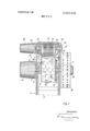
- FIG. I shows a longitudinal section of a device according to the invention close behind a housing wall
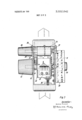
- FIG. 2 shows a vertical cross section through the device
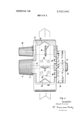
- FIG. 3 shows a plan view of the device, a cover and a guide path being removed and the housing below being in horizontal section;
- FIG. 4 shows a plan view of the headpo'rtion
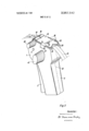
- FIG. 5 is a perspective illustration of the device according to the invention.
- the device consists of a housing body I (FIGS. I and 5) which merges into a handle 2 at the lower end and in the interior of which the essential parts of the mechanism are contained.
- An actuating lever 3 is mounted in the housing I for pivoting about a pin 4. When pressed against the handle 2, it causes a displacement of the shaft 5 ofa die wheel 6 serving as a counterdie, with the latter in a preset position, against a plate 7 out of which there project the lower ends 8 of punches 9.
- the shaft 5 of the die wheel is guided in slots 5: in the housing walls (FIG. 2).
- the operating handle 3 is constructed in the form ofa bellcrank lever. As a whole, it is U-shaped with a working surface 3: extending parallel to the handle 2 and inwardly projecting profile arms.
- Each of these two arms I I contains a slot guide 12 which engages on the shaft 5 of the die wheel.
- the cover 15 further comprises a slot 16 for the passage of the feed pins 23 ofa feed wheel 24. It is further provided with a flange 21 which engages in a detent 22 on the housing I and holds the cover in its closed position.
- the feed wheel 24 is mounted on a shaft 25 as close as possible to the punches 9.
- This feed wheel has a base member in the form of a roll which is at least as wide as the recording medium to be processed.
- the cylindrical surface of the roll is provided with spikes 23, the spacing of which corresponds to the spacing of the feed holes in the recording medium.
- a rachet wheel 26 Rigidly connected to the feed wheel 24 is a rachet wheel 26 which cooperates with a pawl 27.
- the pawl 27 is rigidly connected to a spring 28 which is secured to the operating handle 3 by means of screws 29.
- a locking pawl 30, which is initially tensioned by means ofa spring 31, is'provided for the locking.
- the bearing plate 7 for the punches 9 is part of a bearing bracket 32 which is generally U-shaped
- the bearing bracket carries a comb-shaped spring 33 (FIG. 3), the individual teeth of which act on the punches 9 and hold these in their position of rest.
- the bearing bracket 32 is rigidly connected, by means of screws 34, to the guide path 35 for the recording medium, which forms a cover plate for the open head portion of the housing 1.
- the screws 34 engage through slots in the head portion of the housing 1 so that the position of the bearing bracket in relation to the feed wheel can be varied to a small extent.
- a set screw 36 acting on the bearing bracket 32 on the one hand and the housing 1 on the other hand serves to adjust and secure the set relative position.
- the shaft 25 of the feed wheel also carries. at one side of the housing 1, a rotary knob 38 which is rigidly connected thereto.
- the shaft 5, which carries the die wheel 6, is rigidly connected, at one side of the housing, to an indicator wheel 39 and an associated rotary knob 40. At the other side of the housing, it is rigidly connected to a rotary knob 41.
- the indicator wheel 39 is preferably interchangeably mounted on the shaft and carries, at its circumference, the characters or letters associated with the code determining the arrangement of the holes ofthe die wheel.
- a representation of the set code combination may additionally be associated in a visible manner with each character.
- the setting is effected in relation to a pointer 42 secured to the housing 1.
- the wheel is rigidly connected to a toothed rim 43 in the gaps between the teeth on which, there engages a spring 44 secured to the housing.
- the guide path 35 comprises lateral guide surfaces 45 (FIG. 4) for the recording medium.
- the cover is provided, at its two end faces, with tearing edges 19 and respectively for the recording medium. In addition, it is arched in the region of the feed wheel 24 in such a manner that the feed holes in the recording medium can engage in the spikes of the feed wheel over as great a distance as possible.
- a stop pin 47 which is in line with a stop pin 48 on the handle 2, is provided on the operating handle 3.
- a helical spring 49 which urges the operating handle 3 away from the handle 2 in the position of rest, is mounted over these stop pins 47 and 48.
- the spring 28 and hence a dog 27 serving as a pawl are displaced.
- the dog ispushed forwards out of its position between two teeth of a rachet wheel.
- the spring 48 mounted in the lower region between the actuating lever and the handle urges these two members apart again.
- the die wheel and the punches displaced upwards when the handle is actuated are lowered, being urged downwards back into their initial position by means of the spring 33.
- the dog 27 on the steel spring 28 engaged in a tooth in the rachet wheel connected to the feed roll 24 turns the roll on through a distance which corresponds to the spacing between two groups of holes on the punched tape.
- the spikes 23 on the feed roll, in engagement in a plurality of feed holes convey the punched tape into the next hole position.
- the rotary knob 38 on the shaft 25 of the feed roll 24 permits turning on of the punched tape through any desired number of positions, the dog spring and the locking pawl engaging for each hole combination.
- the die wheel 6 may be provided with dogs instead of with holes 10, which dogs must then always project atthc points at which the punches have to be urged upwards.
- the indicator wheel may also be constructed in the form of a disc the pivot of which is mounted at an angle to the axis of the die wheel and is connected to the die wheel through a toothed rim and gear wheel.
- this form of construction enables two or more revolutions of the roll to correspond to one revolution of the indicator wheel; digits and characters may then be disposed one behind the other, following on the letters, on the same circle as the indicator disc.
- the indicator disc may also be integral with the die wheel.
- the separate die wheel may also be dispensed with if the indicator disc is so arranged and constructed that the counterdies, that is to say either dogs or.
- the housing may be made simpler and kept smaller.
- a die wheel is shown which is adapted for the punching of punched tapes in five-track code.
- the device may, of course, also be constructed appropriately for other codes.
- the die wheel it is conceivable for the die wheel to be mounted in the device so as to be interchangeable for another, for example for a six-track or seven-track code.
- the device as a whole may be produced from a metal or plastics material by the injection-moulding or compressionmoulding process.
- a device for punching a striplike record medium comprising a pistol-grip-shaped casing, said casing having a record medium guide track along the top surface of said casing, a die wheel rotatably mounted in said casing and on which there are provided pressure surfaces corresponding to punch codes, a set of movable punches disposed between said die wheel and said guide track, said guide track being provided with a set of first openings through which said punches can extend, means for biasing said punches into a recessed rest state, a transport wheel rotatably mounted in said casing adjacent said punches, a further opening being provided in said guide track, said transport wheel having a plurality of engaging means extend ing through said further opening for engaging said record medium, a lever arm pivotably mounted on said casing, means connecting said lever arm to said die wheel so that when said lever arm is moved from a first position to a second position said die wheel urges certain of said punches through said first openings, and means connecting said lever arm to said transport wheel for rotating said transport wheel
- the device of claim 1 further comprising a cover over said guide track, said cover being provided with a set of openings for permitting the entry of the ends ofsaid punches.
- the device of claim 1 further comprising an indicator wheel external to said casing and coupled to said die wheel.
- the device of claim 3 further comprising a rotary knob coupled to said die wheel.
- the device of claim 5 further comprising a rotary knob external to said casing and connected to said transport wheel 7.
- said casing comprises two unitary shells which are mirror images, said unitary shells being rigidly connected together.
- the device of claim 1 further comprising a bearing member for supporting said punches, a screw and slot com
Landscapes
- Physics & Mathematics (AREA)
- General Physics & Mathematics (AREA)
- Engineering & Computer Science (AREA)
- Theoretical Computer Science (AREA)
- Perforating, Stamping-Out Or Severing By Means Other Than Cutting (AREA)
Applications Claiming Priority (1)
| Application Number | Priority Date | Filing Date | Title |
|---|---|---|---|
| DE19671549730 DE1549730A1 (de) | 1967-11-29 | 1967-11-29 | Geraet zum Lochen von Aufzeichnungstraegern |
Publications (1)
| Publication Number | Publication Date |
|---|---|
| US3552642A true US3552642A (en) | 1971-01-05 |
Family
ID=5676683
Family Applications (1)
| Application Number | Title | Priority Date | Filing Date |
|---|---|---|---|
| US775744A Expired - Lifetime US3552642A (en) | 1967-11-29 | 1968-11-14 | Device for punching recording media |
Country Status (6)
| Country | Link |
|---|---|
| US (1) | US3552642A (de) |
| AT (1) | AT289432B (de) |
| BE (1) | BE724443A (de) |
| CH (1) | CH483064A (de) |
| FR (1) | FR1590298A (de) |
| GB (1) | GB1209549A (de) |
Cited By (1)
| Publication number | Priority date | Publication date | Assignee | Title |
|---|---|---|---|---|
| US6104987A (en) * | 1997-10-03 | 2000-08-15 | The Nash Engineering Company | System for monitoring dryer drum temperatures |
Citations (3)
| Publication number | Priority date | Publication date | Assignee | Title |
|---|---|---|---|---|
| US3232526A (en) * | 1963-04-04 | 1966-02-01 | H & B Inc | Hand operated tape punching machine |
| US3278117A (en) * | 1964-05-06 | 1966-10-11 | Robins Industries Corp | Portable tape perforator |
| US3331483A (en) * | 1965-07-01 | 1967-07-18 | Taller & Cooper Inc | Manual alpha-numeric hand operable card punch |
-
1968
- 1968-10-29 FR FR1590298D patent/FR1590298A/fr not_active Expired
- 1968-11-13 GB GB53743/68A patent/GB1209549A/en not_active Expired
- 1968-11-14 US US775744A patent/US3552642A/en not_active Expired - Lifetime
- 1968-11-15 CH CH1710768A patent/CH483064A/de not_active IP Right Cessation
- 1968-11-25 AT AT1142468A patent/AT289432B/de not_active IP Right Cessation
- 1968-11-25 BE BE724443D patent/BE724443A/xx unknown
Patent Citations (3)
| Publication number | Priority date | Publication date | Assignee | Title |
|---|---|---|---|---|
| US3232526A (en) * | 1963-04-04 | 1966-02-01 | H & B Inc | Hand operated tape punching machine |
| US3278117A (en) * | 1964-05-06 | 1966-10-11 | Robins Industries Corp | Portable tape perforator |
| US3331483A (en) * | 1965-07-01 | 1967-07-18 | Taller & Cooper Inc | Manual alpha-numeric hand operable card punch |
Cited By (1)
| Publication number | Priority date | Publication date | Assignee | Title |
|---|---|---|---|---|
| US6104987A (en) * | 1997-10-03 | 2000-08-15 | The Nash Engineering Company | System for monitoring dryer drum temperatures |
Also Published As
| Publication number | Publication date |
|---|---|
| FR1590298A (de) | 1970-04-13 |
| GB1209549A (en) | 1970-10-21 |
| CH483064A (de) | 1969-12-15 |
| AT289432B (de) | 1971-04-26 |
| BE724443A (de) | 1969-05-02 |
Similar Documents
| Publication | Publication Date | Title |
|---|---|---|
| US3630336A (en) | Proportional spacing printer incorporating word underscore control | |
| US4032946A (en) | Apparatus for selling betting tickets | |
| US2800539A (en) | Program device | |
| US2838361A (en) | Time recording apparatus | |
| US3552642A (en) | Device for punching recording media | |
| US2846932A (en) | Photographic type composition | |
| US2007391A (en) | Record controlled punch | |
| SU803854A3 (ru) | Устройство дл выборочного печа-ТАНи | |
| US1124820A (en) | Recording mechanism. | |
| DE69521929T2 (de) | Verfahren und Vorrichtung zum Lesen von Film Information für eine Kassette | |
| US3693516A (en) | Photocomposing machine with flexible fiber optics scanning member | |
| US3559792A (en) | Digital display and control device for the setting, justification, and control of lines of print | |
| GB1569626A (en) | Phototypesetting machines | |
| US3331483A (en) | Manual alpha-numeric hand operable card punch | |
| US3232526A (en) | Hand operated tape punching machine | |
| US3183829A (en) | Check writing machine | |
| US3672565A (en) | Punched tape controlled card puncher | |
| US3353441A (en) | Superimposable card system based on novel records | |
| US2059805A (en) | Verifier | |
| US3219806A (en) | Typesetting apparatus | |
| US3049989A (en) | Record punching machine | |
| US1506381A (en) | Method of and apparatus for perforating record sheets | |
| US3476876A (en) | Information encoding and transmitting apparatus | |
| USRE25128E (en) | Fig-iy | |
| US3554069A (en) | Record member punch |