US3557741A - Construction of ships - Google Patents
Construction of ships Download PDFInfo
- Publication number
- US3557741A US3557741A US662090A US3557741DA US3557741A US 3557741 A US3557741 A US 3557741A US 662090 A US662090 A US 662090A US 3557741D A US3557741D A US 3557741DA US 3557741 A US3557741 A US 3557741A
- Authority
- US
- United States
- Prior art keywords
- vessel
- cargo
- bow
- formation
- stern
- Prior art date
- Legal status (The legal status is an assumption and is not a legal conclusion. Google has not performed a legal analysis and makes no representation as to the accuracy of the status listed.)
- Expired - Lifetime
Links
Images


Classifications
-
- B—PERFORMING OPERATIONS; TRANSPORTING
- B63—SHIPS OR OTHER WATERBORNE VESSELS; RELATED EQUIPMENT
- B63B—SHIPS OR OTHER WATERBORNE VESSELS; EQUIPMENT FOR SHIPPING
- B63B15/00—Superstructures, deckhouses, wheelhouses or the like; Arrangements or adaptations of masts or spars, e.g. bowsprits
-
- B—PERFORMING OPERATIONS; TRANSPORTING
- B63—SHIPS OR OTHER WATERBORNE VESSELS; RELATED EQUIPMENT
- B63B—SHIPS OR OTHER WATERBORNE VESSELS; EQUIPMENT FOR SHIPPING
- B63B35/00—Vessels or similar floating structures specially adapted for specific purposes and not otherwise provided for
- B63B35/66—Tugs
- B63B35/665—Floating propeller units, i.e. a motor and propeller unit mounted in a floating box
Definitions
- This invention relates to the construction of a [54] CONSTRUCTION OF SHIPS composite ship, comprising a motive pusher or after part, which houses propulsion machinery, steering gear and controls, and at least one cargo-holding part which comprises a bow provided with mooring and anchoring equipment.
- the several parts are attachable together rigidly or with a degree of vertical flexibility to provide a composite ship which is stable and controllable at sea and in port.
- An object of the invention is to provide a motive part which when separated is an independently seaworthy vessel, by the provision of a suitable bow formation lacking in the motive parts of known composite ships.
- the invention provides, as the motive part of a composite ship, a seagoing vessel having a hull equipped with propulsion machinery and steering gear, said hull having a bow formation comprising static latching means adapted automatically to connect the vessel to a complementarily formed stern part of a cargo-holding vessel below water level, and mechanical means adapted for the connection of the vessels together at deck level, said connecting means serving jointly to afford transverse and longitudinal abutment and resistance to sheer, torsion and longitudinal bending.
- the underwater connecting means may include, at the forefoot of said bow fonnation, a downwardly open recess adapted to receive a complementary upward projection at the stern of said cargo-holding vessel, formed to transmit forces laterally and rearwardly to said projection.
- the invention also provides a cargo-holding vessel adapted to be propelled and maneuvered by a seagoing vessel as aforesaid and having complementary stern formation and deck connection means; and a composite ship comprising such two vessels when connected together.
- a motive part usually a pusher or stern part
- Said cargo part or a foremost one of a series of such cargo parts may comprise a bow part, or such bow, provided with mooring and anchoring equipment, may be provided as a separate part.
- the several parts are attachable together either rigidly or with a greater or less degree of vertical flexibility to provide a composite ship which is stable and controllable at sea and in port.
- the basic concept of such composite vessels is that the motive part should be better utilized, in that it is not immobilized during loading or unloading of a cargo part, but can be transferred and attached to another cargo part ready to be moved.
- An object of the present invention is to provide a composite vessel comprising a motive part which has a bow formation such as to render said part capable of proceeding safely to sea, and a cargo-holding part the after end of which is adapted for firm connection to said bow formation of the motive part.
- the latter is thus enabled, if required, to leave one cargo-holding part in one port, and proceed by sea to another port whereat it can be connected to another cargo-holding part.
- the motive part may be adapted to serve as a tug boat, for the several purposes of such a tug boat, including the towing by line of the aforesaid cargo-holding part or of barges or lighters.
- the invention provides, for use as the motive part of a composite ship, or independently, a seagoing vessel having a hull equipped with propelling machinery and steering gear, said hull having a bow formation comprising static latching means adapted automatically to connect the vessel to a complementarily formed stern part of a cargo-holding vessel below water level, and mechanical means adapted for the connection of the vessels together at deck level, said connecting means serving jointly to afford transverse and longitudinal abutment and resistance to sheer, torsion and longitudinal bending.
- the underwater connecting means may include, at the forefoot of the bow formation, a downwardly open recess adapted to receive a complementary upward projection at the stern of said cargo-holding vessel, the recess being formed to transmit force laterally in both directions, and rearwardly, to said projection.
- Said bow formation may comprise a V-form stem adapted to engage in a complementary V-form recess at the stem of said cargo-holding vessel.
- said bow formation may have at deck level a substantially straight transverse portion adapted to transmit propelling force, said portion projecting forwardly and laterally over a substantiallyV-form stem.
- the bow formation may have a transverse peak bulkhead forward of said recess and a ballast tank capable of being filled and emptied to vary the fore-andaft trim of the vessel to effect respectively engagement and disengagement of said recess with the complementary projection at the stern of the cargo-holding vessel.
- Said ballast tank may have valve means controllable from deck level and a duct whereby it is rapidly dischargeable by gravity into a stemward tank in the vessel for rapidly varying the fore-and-aft trim from a bow-down attitude to a bow-up attitude for disengagement of said recess from said projection.
- connection means at deck level comprise a plurality of tension members, in equal groups on each side of the centerline, pivotally mounted on the forepeak and adapted to be angularly displaced forwardly of the bow for engagement of their forward ends with anchorages on the stern formation of said cargo-carrying vessel, each of said tension members including a tensioning device.
- a vessel as aforesaid may have a wheel house mounted on elevator means for raising said wheel house to afford visibility forward over the length of a cargoholding vessel when secured to the bow formation.
- the invention further provides a cargoholding vessel or barge, adapted to be propelled and maneuvered by a seagoing vessel as hereinbefore recited and having a formation of its stern comprising static means adapted automatically to connect said stem to the complementarily formed bow of said seagoing vessel below the waterline,-and mechanical means adapted for the connection of the vessels together at deck level.
- Such cargo-holding vessel or barge may have a formation of its stern comprising a rearwardly open cavity which is upwardly, forwardly and laterally divergent from the keel level to the deck level, and an upward projection in said cavity at or adjacent said keel level, said projection being adapted, when engaged in said recess in the forefoot of said seagoing vessel, to react to force applied laterally in both directions, and rearwardly.
- connection means at deck level may comprise a plurality of tensile members, in equal groups on each side of the centerline, pivotally mounted on the forepeak and adapted to be angularly displaced forwardly of the bow for engagement of their forward ends with anchorages on the stern formation of said cargo-carrying vessel, each of said tensile members including a tensioning device. At least some of each group of tensile members may be disposed in tension parallel to the centerline of the vessel. Further, or alternatively, at least some of each group of tension members may be disposed in tension forwardly divergent from the centerline of the vessel.
- Said seagoing vessel may further have, in combination with said connection means at deck level, a plurality of plates extending along the margin of the forepeak deck and secured to a plurality of straps pivoted on pins parallel to said margin, said plates being displaceable to attitudes of forward projection over said margin which the forward ends of said straps are connectable to clevises serving as anchorages on the stern formation of said cargo-carrying vessel.
- said tensile members may have substantially rigid links mounted on said forepeak on pivots slidable in longitudinal guide means, and having means to apply tensile force to said links, such as horizontal hydraulic ram means. Further, there may be provided opposed ram means operable to relax tension in said links.
- the free ends of said links may have eyes adapted to be engaged with removable pins in anchorages upon the stern part of said cargo-holding vessel, or hooks adapted to engage upon anchorage pins upon the stern part of said cargo-holding vessel.
- the vessel may further have upon said bow at least one pair of buttress means, between which said links are disposed when extended horizontally forwards to resist lateral forces applied to said links, and at least one bar slidably engageable in eyes in said pair of buttresses located to hold said bar across said links.
- the invention also extends to a composite ship comprising a motive part which is a seagoing vessel in any of the variants thereof as hereinbefore recited in combination with a cargoholding vessel having a stern formation complementary to the bow formation of said motive part, also as hereinbefore recited.
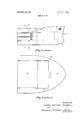
- FIG. 1 is a side elevation, partly in longitudinal section, and broken away to omit multiple hold space, of a composite ship;
- FIG. 2 is a plan view of the same
- FIG. 3 is a fragmentary perspective view of the bow formation of the motive part of said ship;
- FIG. 4 is a fragmentary longitudinal section of the connecting parts of said ship
- FIGS. 5 and 6 are respectively a plan view and a perspective view of the stern formation of a cargo-holding part of said ship;
- FIG. 7 is a side elevation, similar to FIG. 1, of another embodiment of composite ship;
- FIG. 8 is a plan view of the same
- FIGS. 9 and 10 are transverse sections on the lines IXIX and X-X respectively of FIG. 7;
- FIG. 11 is a fragmentary plan view of a stern formation of the cargo-holding component
- FIG. 12 is a fragmentary plan view of a variant arrangement of connecting means
- FIG. 13 is a plan view of deck level connecting means for a ship as shown in FIG. 2;
- FIG. 14 is an elevation of the same.
- FIG. 15 is a horizontal section of the deck structure on the line XV-XV of FIG. 14;
- FIGS. 16 and 17 are respectively a fragmentary plan view and an elevation of an alternative embodiment of deck level connecting means
- FIG. 18 is an elevation showing modifications of said embodiment.
- FIG. 19 is a transverse elevation of shear restraining means.
- the composite ship shown in FIGS. 1-6 comprises a sternwardly located motive part 1 and a forward cargo-holding part 2.
- the motive part I is fitted with at least one propeller 3 driven by a power plant housed in the hull of said part, and with a rudder 4 controlled by the usual steering gear from a deck house 5.
- Said part 1 has a V-form bow 6 which fits into a complementarily formed stern of the cargo-holding part 2.
- the latter consists of a hull provided with a bow 7 equipped with bow anchors and windlass means, and its intermediate part contains a series of holds 9 with deck hatches 10.
- the motive part 1 has a bow formation including a stem 11 with a recess 12 at its forefoot, as indicated in elevation in FIGS. 1 and 4 and shown in perspective in FIG. 3.
- the foredeck 8 is substantially flat and of V-form, apex forward, in plan, or at least with fiat portions along the margins of said deck 3.
- the latching means provided to connect the parts 1 and 2 together automatically below water level comprise in the motive part, at its forefoot said recess 12, which is transversely disposed and has a shallow forwardly V-formor convex form in plan. More particularly, as illustrated in FIG.
- the recess 12 comprises two lateral portions 13 each of which is rearwardly inclined from its end nearer the middle to its outer end, and a central portion 14, which at least has a forward face perpendicular to the longitudinal centerline of the part 1, the forefoot merging, forward of the recess 12, into the relatively sharp stem 11.
- the recess 12 is defined by relatively deeper and shallower rear and forward walls 15 and 16, the rear wall rising from the level of the keel, and the front wall descending to a horizontal portion 17 at the base of the stem 11, at a somewhat higher level than the keel.
- the cargo-holding part has at its stern a cavity 18 the formation of which is complementary to the above described bow formation of the motive part, this cavity being generally as shown in FIG. 6.
- a cavity 18 the formation of which is complementary to the above described bow formation of the motive part, this cavity being generally as shown in FIG. 6.
- a rearwardly extending shelf 19 on the rear margin of which is superimposed a transverse rib 20, complementary both in plan and section to the recess 12 in the forefoot of the motive part.
- the upper part of the cavity is constituted by divergent walls 21, 22 which are disposed to fit fairly closely, if desired with the interposition of fenders, about the stem and the bow plating diverging from said stem, of the motive part 1.
- the rear wall 15 of the recess 12 and the corresponding rear wall of the rib 20 are as shown inclined forwardly and upwardly, while the forward wall 16 of said recess and the corresponding wall 23 of the rib are substantially vertical.
- the bow formation of the part 1 is substantially of the ice-breaker type, the stem 11 having a portion 24 at a substantial inclination (e.g., about 5060) to the horizontal up to approximately the water line, and an upper portion 25 the inclination of which is nearer to the vertical.
- the V-form in plan of the bow of the part 1 and the corresponding form of the cavity 18 at the stern of the part 2 facilitate the connection together of the two parts to provide a rigid key joint.
- Propulsive force is transmitted from the part 1 to the part 2 by the formation of the bow 6 locked into the stern cavity 18, and lateral steering forces are similarly applied to the part 2 from the part 1 by the interlocking, assisted by the form of the recess 12 and rib 20.
- the latter, underwater, connecting means may be interengaged simply by propelling the motive part 1 so that its bow 6 enters the cavity 18 at the after end of the cargo-holding part 2, said cavity serving as a guide to align the two parts. Since both parts are floating, the bow of the motive part is able to ride over the rib 20 at the after end of the cargo part until said rib engages in the recess 12 at the forefoot of said bow thus latching the two parts together.
- an initial difference in draughts to enable the forefoot of the motive part to clear the rib 20 of the cargo part, may be produced or compensated by liquid displacement within either one or both of the two parts, or between one or both parts and the sea, this difference of draught thereafter being nullified by further liquid displacement either to depress the bow of the motive part 1 or raise the stern of the cargo-holding part 2.
- the motive part is of course provided with power generation means, crew quarters and control means in the bridge or deck house 5, as well as mooring and anchoring deck equipment.
- the motive part is of course provided with power generation means, crew quarters and control means in the bridge or deck house 5, as well as mooring and anchoring deck equipment.
- the cargo-holding part 2 may be a single unit comprising the bow 7 with a series of holds.
- a cargoholding part may comprise a plurality of units connected or connectable together, one of said units comprising a bow portion as aforesaid.
- Such a plurality of cargo-holding units may have mutual connecting means identical with or similar to the means above described for connection to the motive part, so that a cargo unit comprising a bow may be connectable to the motive part either directly or with the intermediary of another cargo unit which, except for connecting means as aforesaid at its forward and after ends, has a constant cross section.
- Means operable to connect the parts 1 and 2 together at deck level may comprise tension members 26 extending substantially parallel to the centerline of the ship across the fissure between the foredeck 8 of the motive part, and the after part of the deck 27 of the cargo-holding part.
- the deck level connecting means 26 may be extended between the two parts, and if desired subjected to tension so as to provide a firm connection for the maneuvering of the composite ship by the propulsion means and the steering gear of the motive part 1.
- FIGS. 7 II is of a composite ship similar in principle to that above described, but with the interconnecting means, between a motive part 30 and a cargo-holding part 31, somewhat modified to permit said motive part to operate more satisfactorily, when disconnected, as an independent seaworthy ship, and preferably as a seagoing tug. Otherwise, equivalent parts in this embodiment are indicated by like reference numerals.
- the modified bow formation of the motive part 30 provides a forefoot having on the centerline a recess 32 which extends aft from a forepeak bulkhead 33 defining in said bow a ballast tank 34.
- the front wall of the recess 32 has a vertical portion 35 which merges with a relatively large radius into an upper rear wall 36 which slopes downwardly to the level of the keel 60, and further merging sharply atits lower end into the base 38 of the stem 39.
- the lateral walls 37 of said recess 32 (see FIG. 9) are substantially vertical.
- the upper and forward faces of said recess may be lined with a durable and resilient material such as lignum vitae or Tufnol.
- the stem 39 rises at a small angle to the vertical, between relatively sharply divergent sides 40 of the bow, to a level at or adjacent the water level, above which the foredeck 41 extends forwardly and laterally over the stem to provide a squared nose 42, that is, a nose having a straight transverse portion 43 with rounded corners 44.
- the forefoot aft and especially forward of the recess 32 is of stout construction to withstand both tensile and compressive forces.
- This forefoot portion which is effectively a lower stem bar, may be forged, cast or fabricated to provide a structure rigid in all planes.
- the after part of the cargo-holding vessel 31 is formed with a cavity 48, which at deck level has a plan form including a straight transverse portion 45 to be abutted by the squared nose 42 of the motive part 30, with the intermediary of a fender 46 secured about said nose, and bearer members 47, for example of durable timber, supported on a ledge 49 adjacent said portion 45.
- Said plan form is further defined by a pair of lateral horn portions 50 extending rearwardly to abut the sides of the motive part 30 with the interposition of fenders 51.
- the portion 52 with the spigot 53 is preferably rigidly and firmly secured in the lower part of the cavity 48, but may alternatively be adjustable displaceable or removable.
- suitable spacing means may be inserted between the surface 45 and the nose fender 46.
- Such spacing means may be desirable, for example, to set the motive part down by the stem to maintain adequate immersion of the propeller 3 during pitching movement.
- the bottom of the cavity 48 forward of the portion 52 may be completely open, or may as shown be provided with slots 54, to permit access of sea water to the residual space between the walls of the cavity 48 and the bow of the motive part 30.
- the lower part of said bow may be engaged on each side by one of a pair of fenders 55.
- the presence of sea water in this residual space does not affect the buoyancy of the composite ship, although it may improve the stability.
- the forward ballast tank 34 may be wholly or partly emptied, to put the motive part in a bow-high attitude while having its bow inserted in the cavity 48, to enable the forefoot 38 to ride over the spigot 53.
- the tank 34 may then be partly or wholly or further filled to lower the bow until the recess 32 engages firmly over the spigot 53.
- Deck level connecting means shown as tensile links 56, which may need to be heavy to afford the required strength, may contribute to the lowering of the bow when swung forward to the positions shown, about pivots 57 at their after ends, from rearwardly inclined stowage positions indicated at 560.
- the ballast tank 34 may be at least partly emptied; For effecting rapid displacement from a stern-high attitude, as shown in FIG. 7, to a bow-high attitude, the water in the tank 34 may be quickly and at least partly transferred, by gravity, under control of a valve 61 preferably operable from deck level, through a longitudinal duct 58, to a ballast tank 59 adjacent the stern of the part 30, which tank 59 may later be pumped out.
- the tank 34 may also be adapted to be at least partly filled under gravity, for example, through a sea cock (not shown) likewise controlled from deck level.
- the cargo-holding part 31 may comprise, between the conventional bow and forecastle structure 7 and the stern structure 48, 50, a hull having a substantially constant transverse section, as shown for example in FIG. 10.
- the vessel as illustrated is intended for use primarily as an ore/oil carrier, and comprises a series of center holds 9, with hatch covers 10, wing tanks 63 for oil, and further tanks 64 below the holds which may be left at least partly empty for buoyancy, or other wise may contain oil or water ballast.
- This cargo-holding part may, for example, have a cargo dead weight capacity of 6,000 tons, requiring the motive part 30 to deliver at the propeller shaft a force of the order of 2,000 horsepower.
- FIG. 12 shows a variant of the complementary bow and stem formations of the parts 30 and 31, wherein deck level connecting means 65 are disposed so as to diverge forwardly to their anchorages on the barge 31, thus serving better to transmit some of the lateral forces and enabling the provision of a more conventional and rounded bow on the motive part.
- the wheel house 67 may be mounted on extensible supports 68, which enclose similarly extensible control transmission means, and by which said wheel house may as required be raised to the position shown or lowered to a position on the top of or at least partly within the deck house 5.
- Means may be provided on the stern of the cargo-holding part 31, for mechanical handling over said stern and the foredeck 41 of the tug, and particularly for handling of the deck connection means 56.
- Such mechanical handling means may comprise a transverse gantry with hoisting means or, as shown, a pair of derricks on posts 69, with winch means 70 mounted on the stern deck.
- the tug-and-barge composite shown in FIGS. 7 and 8 is adapted for relatively slow speed, eg, about 79 knots, with the tug or motive part 30 adapted for frequent independent operation or sea voyages, or for line towing of the barge part 31 or conventional barges or lighters, and as a tugboat generally. Accordingly the form and bow structure of the part 30, at least adjacent and above the water line, may be robust as required for seagoing tugs. Fairing at the connection between the two parts is not critical, and the bow and stem forms of the tug and barge respectively may therefore be such as to facilitate their separate usages.
- a composite ship as shown in FIGS. 1 and 2 may be adapted to serve as a cargo liner or deep sea cargo ship, for example, having a cargo capacity of l2,000 15,000 tons dead weight, and a speed up to 21 knots.
- the contours of the bow of the motive part and the stern of the cargo-holding part are therefore such as to provide a composite hull as smoothly faired as possible, for high speed performance.
- the motive part 1 would not normally be adapted for independent operation outside harbors.
- An advantage of the cavity form of the stern of the cargoholding part is that it is s self-aligning when coupling is to be effected at an exposed berth or in choppy sea conditions, as compared with the components of composite ships heretofore proposed. Further, the provision of a simple, automatic interlock adjacent the keel level facilitates subsequent connection and bracing up at deck level, and eliminates external connections at or adjacent the water level. In the event of rupture of the deck level connections, there is a fail-safe" feature in that the two components may be rapidly separated with the aid of wave motion and by ballast displacement in the motive part as hereinbefore described.
- FIGS. 13-15 illustrate in further detail an arrangement of deck connecting means indicated diagrammatically at 26 in FIGS. 1 and 2. While such connecting means are particularly suitable for connecting together, as a composite ship, a motive part which is an independently seaworthy vessel, and a cargoholding part, having bow and stem formations as shown in FIGS. 1-6, they are also suitable for other kinds of composite ship not having the described automatic connecting means adjacent the keel.
- connection means include a series of plates 71 mounted on the foredeck 8 of the motive part, there being at least one plate disposed along each margin of the V-form bow.
- Each plate is secured, as by welding, to a plurality of straps 72, pivotally mounted each on a pin 73 in lugs 74 which penetrate the deck and are firmly secured to oblique deckhead ribs 75 as shown in FIG. 15.
- the pins 73 are thus disposed parallel to the margin of the foredeck, but the straps 72 are bent adjacent the pivots to extend parallel to the centerline of the vessel as indicated diagrammatically at 26 in FIG. 2.
- the plates 71 are displaceable to the horizontal attitudes as shown from upright attitudes 71a whereat they may be disposed as wavebreaks when the motive part 1 is disconnected.
- clevis members 77 For connecting the two parts of the composite ship together at deck level, when the plates 71 have been extended forwardly as shown the free ends of the straps 72 are connected by removable pins 76 into clevis members 77 which are themselves pivoted on pins 78 mounted in pairs of lugs 79, likewise firmly secured beneath the deck to longitudinally extending ribs 80.
- the clevises 77 may each include a tensioning device adapted to be tightened to take up adjustment of the straps 72, which for this purpose may further be supported on rollers 81 mounted on the after deck 27 of the cargo-holding part 2.
- tensile members 82 made for example as shown of wire cable, each of which is mounted on a pin 83 at right angles to the centerline of the ship, such pin being supported in a pair of lugs 84 which are similarly firmly secured below deck level to longitudinally extending ribs 05.
- Adjacent its pivotal mounting each of the members 82 is provided with a turnbuckle device 86 for tensioning.
- the free ends of these members 82 are adapted to be anchored upon removable pins 87 between pairs of lugs 88 which are in a similar manner secured to longitudinal ribs 89 beneath the deck 27 of the cargo-holding part.
- FIGS. 16 and 17 illustrate another embodiment of deck connection means more particularly applied, as shown, to an arrangement of a composite ship as illustrated in FIGS. 7 and 8.
- This arrangement of connecting means is also suitable for connection together at deck level of the parts of other kinds of composite ships which do not have the described automatic connecting means adjacent the keel.
- the connecting means comprise links 56 which are pivotally mounted on preferably removable pins 57 so as to extend parallel to the centerline of the ship, and in equal number on either side of said line.
- the pins 57 are adapted to be supported in guide members 91 having longitudinal slots 92 wherein are slidable blocks 93 having circular bores in which the pins 57 are housed.
- a pair of hydraulic rams 94 Associated with the blocks 93, and firmly mounted on the foredeck 41 of the motive part 30 there are a pair of hydraulic rams 94 disposed to apply tension to the links 56 by their piston members 95, when extended, bearing on the blocks 93.
- each pair of links 56 shackle means 98 by which initial or additional tension may be applied to the links 56, or by which if required the links may be lifted after removal of the pins 57.
- Each of said links 56 may be upwardly and rearwardly pivoted, about the pins 57, when the motive part 30 of the ship is disconnected from the cargoholding part, to a stowage position where the links may rest at least partly upon bufier members 99 supported above the deck 41.
- the links 56 When the two parts of the composite ship are to be connected together, the links 56 may be brought to horizontal attitudes in forward extension over the stern part of the deck of the cargo-holding part 31, the free ends of the links 56 having eyes 100 through which may be passed a removable pin 101, similar to the pin 57, mounted in suitable fixed lugs.
- the rams 94 After insertion of the pins 101 the rams 94 may be extended to apply the requisite tension to the links 56.
- Said rams upon closure of their feed valves may be positively locked by the hydraulic fluid or alternatively may be controlled by relief valve means so as to be capable of relaxing under excessive tensile stress in the links.
- An object of such controlled relaxation may be to enable the motive part to settle slightly by the stem, thus tending to keep the propeller immersed.
- the links 56 means for applying shear restraints to said links.
- Such means comprise, as shown in FIGS. 16 and 17, on the foredeck 41 of the motive part, pairs of buttresses 102 between which the links are disposed, said buttresses having apertures 103 through which can be passed transversely removable shear pins 104.
- the pins 104 have at their ends eyes 105 by which they may be inserted and withdrawn, the insertion being effected for example by a portable ram 106 and withdrawal for example by shackle means 107 attachable to a cable which is passed to a suitably disposed winch.
- the pins 104 extend transversely across the links 56 so that these are held down by said pins for example upon supporting rollers 108 on the deck 41.
- buttress members 109 likewise in pairs on either side of the paris of links 56, which have apertures for the passage of similar shear pins 110 to extend transversely over the forward ends of the links 56 and hold them down upon rollers 111 on the deck of the part 31.
- Said buttress members 109 may as shown in FIG. 8 also be extended to afford apertures for the passage of the link end pins 101.
- FIG. 18 illustrates a modification of the links 56 and the means whereby their forward ends are connected to the pins 101 on the deck of the motive part 31.
- the links 56 which may be pivotally mounted as above described on the deck 41 of the motive part, have at their forward ends hooks 112 adapted to engage the pins 101.
- hooks 112 adapted to engage the pins 101.
- the links In order to afford automatic engagement of the hooks 1 12 with the pins 101 as the links are moved forwardly to establish the connection, there are provided on the deck of the part 31 pairs of ramps 113, and the links have lateral jockey rollers 114 disposed to ride over said ramps. As indicated in FIG.
- the rollers 114 ride up the oblique surfaces which at its lower end merges mo the upper surface of said beam and at its upper end merges into a face extending rearwardly and downwardly to said upper surface, to engage upwardly in said recess in the forefoot of said seagoing vessel, and the upper part of said cavity is adapted to transmit forward propulsive force and lateral steering forces applied by the upper part of the bow formation of said seagoing vessel.
- a cargo-holding vessel according to claim wherein said cavity is a V-form recess, adapted to fit closely about the V-form stem of said seagoing vessel.
- a cargo-holding vessel according to claim 10 wherein said cavity has at its upper part a transverse straight portion for abutment by a straight transverse portion of the bow formation of said sea-going vessel, and a pair of rearwardly extending lateral horn portions to abut the sides of said seagoing vessel.
- a composite ship comprising a motive part which is a seagoing vessel in combination with a cargo-holding vessel, said seagoing vessel having a hull equipped with propulsion machinery and steering gear, said hull having a keel and a bow formation comprising a stern, a forefoot and an upper part, said bow formation including static underwater latching means adapted to interact automatically when brought into register with a complementarily formed static stern part of said cargo-holding vessel for rigidly connecting the two vessels together below water level, said cargo-holding vessel having a keel and a stern formation including an underwater latching part adapted to interact automatically with said underwater latching means of said seagoing vessel, and mechanical means for connecting the vessels together above water level, said underwater latching means and part and said above water level connecting means serving jointly to afford transverse and longitudinal abutment and resistance to sheer, torsion and longitudinal bending.
- said underwater latching means of said seagoing vessel includes, at the forefoot of said bow formation, a downwardly open recess
- said stern formation of said cargo-holding vessel includes a rearwardly open cavity which is upwardly, forwardly and laterally divergent from the keel level to above water level of said cargo-holding vessel, and an upward projection in said cavity adjacent said keel level engaged in said recess in the forefoot of said seagoing vessel, said recess being formed to transmit force laterally in both directions, and rearwardly, to said projection.
- a vessel according to claim I wherein said above water level connecting means comprise a plurality of tensile members, in equal groups on each side of the centerline pivotal mounting means for said members on the foredeck of said seagoing vessel permitting them to be angularly displaced forwardly of the bow for engagement of their forward ends with anchorages on the stern formation of said cargo-carrying vessel, and means for applying a tensile force to each of said tensile members.
- each of said tensile members has slidable engagement means for its pivotal mounting and at least one hydraulic ram means connected to said mounting for applying rearward tensioning displacement to said mounting.
- a vessel according to claim 20 having in combination with said above water level connecting means a plurality of plates extending along the margin of the foredeck, a plurality of straps secured to said plates, and pins parallel to said margin forming pivots for said straps, said plates being displaceable to attitudes of forward projection over said margin in which the forward ends of said straps are connectable to clevises serving as anchorages on the stern formation of said cargo-carrying vessel.
- a vessel according to claim 25, wherein said means to apply tensile force comprises horizontal hydraulic ram means, and including opposed ram means operable to relax tension in said links.
- a vessel according to claim 28 having ram means disposed upon said bow, forward of said pivots and beneath said links, to raise said links about said pivots.
- Resilient cushion pads 115 may be provided on the deck of the part 31 for the falling forward ends of the links. There may further be provided on the deck 41 of the motive part, beneath the links 56 and adjacent their ends pivoted on the pins 57, lifting rams 116 by means of which, when tension of the links 56 has been relaxed for disconnection of the parts of the ship, the links may be lifted to release the hooks 112 from the pins 101, and likewise to lift the jockey rollers 114 above the level of the forward ends of the ramps 113, to permit the links to be retracted.
- bollards 117 may be provided at the sides of the motive part 30, and similar bollards 118 on the rearwardly projecting parts 50 at the stern of. the cargo-holding part, which bollards may be lashed together by ropes with the aid of the winch 70, for providing further lateral restraint.
- lateral restraining means between the parts 41 and 50 may be provided, at a similar location, as shown in FIG. 19.
- Such means comprises at least one pair of cranked links 120 permanently pivoted at one end upon pins 121 mounted in lugs l22'upon the deck 41 of the motive part.
- These links are adapted to be turned so that their downwardly extending arms may be connected to pins 123 removably mounted in lugs 124 on the decks of the parts 50, whereafter the links may further be secured by removable pins 125 located in further lugs 126 on the deck 41.
- the links When out of use, after removal of the pins 123 and'125, the links may be turned inboard to positions 120A,'wherein they may rest on resilient pads 127 and are preferably suitably secured.
- the underwater connecting means of either embodiment may be made more secure by the provision within the hull of the motive part of at least one retractable pin, adapted to be projected through the recess in said motive part and through registering apertures in the rib or projection provided in the cargo-holding part.
- a pin may be displaceable, and more particularly retractable to permit disconnection of the two parts, by means controllable remotely, for example from the deckhouse of the motive part.
- Deck connection means as hereinbefore described may be modified either by being piv'oted about vertical axes on the foredeck of the motive part, or by being made removable for stowage.
- Removable connection link means as shown in FIGS. 8 and 16 18 may be displaceable by a transverse gantry with hoisting means, or by derricks mounted on the parts 69, on the stern deck of the part 31 as hereinbefore described and shown in FIG. 8.
- electromagnetic bonding may be provided between the end plates of the two parts.
- the recess and the projection of the underwater connecting means may be provided in inverted disposition in said stern and on said bow respectively.
- a seagoing vessel adapted to propel a cargo-holding vessel, having a hull equipped with propulsion machinery and steering gear, said hull having a keel and a bow formation comprising a stem, a forefoot and an upper part, said bow formation including static underwater latching means adapted to interact automatically when brought into register with a complementarily formed static stem part of the cargo-holding vessel for rigidly connecting the two vessels together below water level, and mechanical means for connecting the vessels together above water level, said underwater latching means and said above water level connecting means serving jointly to afford transverse and longitudinal abutment and resistance to shear, torsion and longitudinal bending.
- said underwater connecting means includes, at the forefoot of said bow formation, a downwardly open recess adapted to receive a complementary upward projection at the stern of said cargo-holding vessel, the recess being formed to transmit force laterally in both directions, and rearwardly, to said projection.
- a cargo-holding vessel adapted to be propelled and maneuvered by a seagoing vessel having a hull equipped with propulsion machinery and steering gear, said hull having a bow formation comprising a V-form stem, a forefoot and an upper part, said bow formation including static underwater latching means comprising a downwardly open, transversely extending recess in said forefoot, said cargo-holding vessel having a keel and a stern formation including an underwater latching part adapted to interact automatically with the complementarily formed bow formation of said seagoing vessel for connecting the two vessels together below the water line, and mechanical means for connecting the vessels together above water level.
- a cargo-holding vessel comprises a rearwardly open cavity which is upwardly, forwardly and laterally divergent from the keel level to above water level of said cargo-holding vessel, and an upward projection in said cavity adjacent said keel level, said projection being adapted, when engaged in said recess in the forefoot of said seagoing vessel, to transmit forces applied laterally in both directions, and rearwardly.
- a cargo-holding vessel comprising, adjacent the keel level in said cavity, a rearwardly extending shelf, and said projection is a transverse rib of substantially V-form convex forwardly, in plan upon the rear margin of said shelf to engage upwardly in the said transverse recess in the forefoot of said seagoing vessel, and the upper part of said cavity is adapted to transmit forward propulsive force and lateral steering forces applied by the upper part of the bow formation of said seagoing vessel.
- a cargo-holding vessel comprises a rearwardly open cavity extending upwardly from the keel level and including, adjacent the keel level in said cavity, a transverse beam and an upward projection upon said beam having substantially vertical lateral walls and a forward wall 32.
- a composite ship according to claim 33 wherein said seagoing vessel includes upon said bow at least one pair of buttresses, between which said links are disposed when extended horizontally forwards to resist lateral forces applied to said links and at least one bar slidably engagcable in eyes in said pair of buttresses located to hold said bar across said links. and wherein said cargo-holding vessel includes at least one further pair of buttresses upon its stern between which buttresses said links are disposed when arranged and anchored to afford a tensile connection, and at least one further bar slidably engagcable in eyes in said further pair of buttresses located to hold said further bar across said links adjacent their anchored ends.
Landscapes
- Chemical & Material Sciences (AREA)
- Engineering & Computer Science (AREA)
- Combustion & Propulsion (AREA)
- Mechanical Engineering (AREA)
- Ocean & Marine Engineering (AREA)
- Other Liquid Machine Or Engine Such As Wave Power Use (AREA)
- Earth Drilling (AREA)
- Bridges Or Land Bridges (AREA)
- Revetment (AREA)
- Buildings Adapted To Withstand Abnormal External Influences (AREA)
Abstract
This invention relates to the construction of a composite ship, comprising a motive pusher or after part, which houses propulsion machinery, steering gear and controls, and at least one cargoholding part which comprises a bow provided with mooring and anchoring equipment. The several parts are attachable together rigidly or with a degree of vertical flexibility to provide a composite ship which is stable and controllable at sea and in port.
Description
United States Patent 1111 3,557,741
[72] Inventor James Arthur Teasdale [56] References Cited Whitley England UNITED STATES PATENTS ii gi 21 1967 3,485,200 12/1969 lozza 114 235 3,125,059 3/1964 Verneaux etal 114/235 [45] Painted 1971 3 345 970 10/1967 DeLong 114/235 [73] Ass1gnee Natlonal Research Development Corporation Primary Examiner-Trygve M. Blix London, England Attorney-Cameron, Kerkam & Sutton a British corporation [32] Priority Aug. 23, 1966 [33] Great Britain 37,806/66 ABSTRACT: This invention relates to the construction of a [54] CONSTRUCTION OF SHIPS composite ship, comprising a motive pusher or after part, which houses propulsion machinery, steering gear and controls, and at least one cargo-holding part which comprises a bow provided with mooring and anchoring equipment. The several parts are attachable together rigidly or with a degree of vertical flexibility to provide a composite ship which is stable and controllable at sea and in port.
PATENTEDJANZBIBTI 3557741 snn 10F 8 Ila/1 mm? JAMES ARTHUR 'DZASDALB A T TOENEKY PATENTEDJAN26I97| $557,74
' sum 3 OF 8 f/VVLWTOZ JAMES ARTHUR TEASDALE BY W, fwd m, -Mw
A TTORMEYJ PATENTEI] JAN 26 I971 SHEET t 0F 8 IN VE NT OE JAMES ARTHUR 'IIASDALI'Z PATENTED JAN 26 I97! SHEET 5 BF 8 .l/VIQWTQQ JAMES ARTHUR TEASDALF,
.DY W, W YM/u ATTOHVL'KS' PATENTEDJANZBIQYI 3557.741
The invention provides, as the motive part of a composite ship, a seagoing vessel having a hull equipped with propulsion machinery and steering gear, said hull having a bow formation comprising static latching means adapted automatically to connect the vessel to a complementarily formed stern part of a cargo-holding vessel below water level, and mechanical means adapted for the connection of the vessels together at deck level, said connecting means serving jointly to afford transverse and longitudinal abutment and resistance to sheer, torsion and longitudinal bending.
The underwater connecting means may include, at the forefoot of said bow fonnation, a downwardly open recess adapted to receive a complementary upward projection at the stern of said cargo-holding vessel, formed to transmit forces laterally and rearwardly to said projection.
The invention also provides a cargo-holding vessel adapted to be propelled and maneuvered by a seagoing vessel as aforesaid and having complementary stern formation and deck connection means; and a composite ship comprising such two vessels when connected together.
Various proposals have been made for the shipment of cargo at sea in composite vessels comprising a motive part (usually a pusher or stern part) which houses the propulsion machinery, steering gear and controls, and at least one cargoholding part. Said cargo part or a foremost one of a series of such cargo parts may comprise a bow part, or such bow, provided with mooring and anchoring equipment, may be provided as a separate part. The several parts are attachable together either rigidly or with a greater or less degree of vertical flexibility to provide a composite ship which is stable and controllable at sea and in port.
The basic concept of such composite vessels is that the motive part should be better utilized, in that it is not immobilized during loading or unloading of a cargo part, but can be transferred and attached to another cargo part ready to be moved.
Hitherto it has not been proposed to provide a motive part which is a self-contained seaworthy vessel, and the motive part has been so constructed that it is unsafe except in the sheltered waters of docks and ports.
An object of the present invention is to provide a composite vessel comprising a motive part which has a bow formation such as to render said part capable of proceeding safely to sea, and a cargo-holding part the after end of which is adapted for firm connection to said bow formation of the motive part. The latter is thus enabled, if required, to leave one cargo-holding part in one port, and proceed by sea to another port whereat it can be connected to another cargo-holding part. Alternatively, the motive part may be adapted to serve as a tug boat, for the several purposes of such a tug boat, including the towing by line of the aforesaid cargo-holding part or of barges or lighters. I
The invention provides, for use as the motive part of a composite ship, or independently, a seagoing vessel having a hull equipped with propelling machinery and steering gear, said hull having a bow formation comprising static latching means adapted automatically to connect the vessel to a complementarily formed stern part of a cargo-holding vessel below water level, and mechanical means adapted for the connection of the vessels together at deck level, said connecting means serving jointly to afford transverse and longitudinal abutment and resistance to sheer, torsion and longitudinal bending.
In a seagoing vessel as aforesaid, the underwater connecting means may include, at the forefoot of the bow formation, a downwardly open recess adapted to receive a complementary upward projection at the stern of said cargo-holding vessel, the recess being formed to transmit force laterally in both directions, and rearwardly, to said projection. Said bow formation may comprise a V-form stem adapted to engage in a complementary V-form recess at the stem of said cargo-holding vessel. Alternatively, said bow formation may have at deck level a substantially straight transverse portion adapted to transmit propelling force, said portion projecting forwardly and laterally over a substantiallyV-form stem.
In such a seagoing vessel, the bow formation may have a transverse peak bulkhead forward of said recess and a ballast tank capable of being filled and emptied to vary the fore-andaft trim of the vessel to effect respectively engagement and disengagement of said recess with the complementary projection at the stern of the cargo-holding vessel. Said ballast tank may have valve means controllable from deck level and a duct whereby it is rapidly dischargeable by gravity into a stemward tank in the vessel for rapidly varying the fore-and-aft trim from a bow-down attitude to a bow-up attitude for disengagement of said recess from said projection.
Said connection means at deck level comprise a plurality of tension members, in equal groups on each side of the centerline, pivotally mounted on the forepeak and adapted to be angularly displaced forwardly of the bow for engagement of their forward ends with anchorages on the stern formation of said cargo-carrying vessel, each of said tension members including a tensioning device.
A vessel as aforesaid may have a wheel house mounted on elevator means for raising said wheel house to afford visibility forward over the length of a cargoholding vessel when secured to the bow formation.
The invention further provides a cargoholding vessel or barge, adapted to be propelled and maneuvered by a seagoing vessel as hereinbefore recited and having a formation of its stern comprising static means adapted automatically to connect said stem to the complementarily formed bow of said seagoing vessel below the waterline,-and mechanical means adapted for the connection of the vessels together at deck level.
Such cargo-holding vessel or barge may have a formation of its stern comprising a rearwardly open cavity which is upwardly, forwardly and laterally divergent from the keel level to the deck level, and an upward projection in said cavity at or adjacent said keel level, said projection being adapted, when engaged in said recess in the forefoot of said seagoing vessel, to react to force applied laterally in both directions, and rearwardly.
In a seagoing vessel as herein first recited, said connection means at deck level may comprise a plurality of tensile members, in equal groups on each side of the centerline, pivotally mounted on the forepeak and adapted to be angularly displaced forwardly of the bow for engagement of their forward ends with anchorages on the stern formation of said cargo-carrying vessel, each of said tensile members including a tensioning device. At least some of each group of tensile members may be disposed in tension parallel to the centerline of the vessel. Further, or alternatively, at least some of each group of tension members may be disposed in tension forwardly divergent from the centerline of the vessel.
Said seagoing vessel may further have, in combination with said connection means at deck level, a plurality of plates extending along the margin of the forepeak deck and secured to a plurality of straps pivoted on pins parallel to said margin, said plates being displaceable to attitudes of forward projection over said margin which the forward ends of said straps are connectable to clevises serving as anchorages on the stern formation of said cargo-carrying vessel.
In another embodiment of such seagoing vessel, said tensile members may have substantially rigid links mounted on said forepeak on pivots slidable in longitudinal guide means, and having means to apply tensile force to said links, such as horizontal hydraulic ram means. Further, there may be provided opposed ram means operable to relax tension in said links. The free ends of said links may have eyes adapted to be engaged with removable pins in anchorages upon the stern part of said cargo-holding vessel, or hooks adapted to engage upon anchorage pins upon the stern part of said cargo-holding vessel.
The vessel may further have upon said bow at least one pair of buttress means, between which said links are disposed when extended horizontally forwards to resist lateral forces applied to said links, and at least one bar slidably engageable in eyes in said pair of buttresses located to hold said bar across said links.
The invention also extends to a composite ship comprising a motive part which is a seagoing vessel in any of the variants thereof as hereinbefore recited in combination with a cargoholding vessel having a stern formation complementary to the bow formation of said motive part, also as hereinbefore recited.
The foregoing and other features of the invention will be better understood from the following description, by way of example, of embodiments with reference to the accompanying diagrammatic drawings, wherein:
FIG. 1 is a side elevation, partly in longitudinal section, and broken away to omit multiple hold space, of a composite ship;
FIG. 2 is a plan view of the same;
FIG. 3 is a fragmentary perspective view of the bow formation of the motive part of said ship;
FIG. 4 is a fragmentary longitudinal section of the connecting parts of said ship;
FIGS. 5 and 6 are respectively a plan view and a perspective view of the stern formation of a cargo-holding part of said ship;
FIG. 7 is a side elevation, similar to FIG. 1, of another embodiment of composite ship;
FIG. 8 is a plan view of the same;
FIGS. 9 and 10 are transverse sections on the lines IXIX and X-X respectively of FIG. 7;
FIG. 11 is a fragmentary plan view of a stern formation of the cargo-holding component;
FIG. 12 is a fragmentary plan view of a variant arrangement of connecting means;
FIG. 13 is a plan view of deck level connecting means for a ship as shown in FIG. 2;
FIG. 14 is an elevation of the same; and
FIG. 15 is a horizontal section of the deck structure on the line XV-XV of FIG. 14;
FIGS. 16 and 17 are respectively a fragmentary plan view and an elevation of an alternative embodiment of deck level connecting means;
FIG. 18 is an elevation showing modifications of said embodiment; and
FIG. 19 is a transverse elevation of shear restraining means.
The composite ship shown in FIGS. 1-6 comprises a sternwardly located motive part 1 and a forward cargo-holding part 2. The motive part I is fitted with at least one propeller 3 driven by a power plant housed in the hull of said part, and with a rudder 4 controlled by the usual steering gear from a deck house 5. Said part 1 has a V-form bow 6 which fits into a complementarily formed stern of the cargo-holding part 2. The latter consists of a hull provided with a bow 7 equipped with bow anchors and windlass means, and its intermediate part contains a series of holds 9 with deck hatches 10.
At the zone of connection of the components 1 and 2, the motive part 1 has a bow formation including a stem 11 with a recess 12 at its forefoot, as indicated in elevation in FIGS. 1 and 4 and shown in perspective in FIG. 3. The foredeck 8 is substantially flat and of V-form, apex forward, in plan, or at least with fiat portions along the margins of said deck 3. The latching means provided to connect the parts 1 and 2 together automatically below water level comprise in the motive part, at its forefoot said recess 12, which is transversely disposed and has a shallow forwardly V-formor convex form in plan. More particularly, as illustrated in FIG. 3, the recess 12 comprises two lateral portions 13 each of which is rearwardly inclined from its end nearer the middle to its outer end, and a central portion 14, which at least has a forward face perpendicular to the longitudinal centerline of the part 1, the forefoot merging, forward of the recess 12, into the relatively sharp stem 11. The recess 12 is defined by relatively deeper and shallower rear and forward walls 15 and 16, the rear wall rising from the level of the keel, and the front wall descending to a horizontal portion 17 at the base of the stem 11, at a somewhat higher level than the keel.
The cargo-holding part has at its stern a cavity 18 the formation of which is complementary to the above described bow formation of the motive part, this cavity being generally as shown in FIG. 6. At the bottom of the cavity there is a rearwardly extending shelf 19, on the rear margin of which is superimposed a transverse rib 20, complementary both in plan and section to the recess 12 in the forefoot of the motive part. The upper part of the cavity is constituted by divergent walls 21, 22 which are disposed to fit fairly closely, if desired with the interposition of fenders, about the stem and the bow plating diverging from said stem, of the motive part 1.
The rear wall 15 of the recess 12 and the corresponding rear wall of the rib 20 are as shown inclined forwardly and upwardly, while the forward wall 16 of said recess and the corresponding wall 23 of the rib are substantially vertical. The bow formation of the part 1 is substantially of the ice-breaker type, the stem 11 having a portion 24 at a substantial inclination (e.g., about 5060) to the horizontal up to approximately the water line, and an upper portion 25 the inclination of which is nearer to the vertical. The V-form in plan of the bow of the part 1 and the corresponding form of the cavity 18 at the stern of the part 2 facilitate the connection together of the two parts to provide a rigid key joint.
Propulsive force is transmitted from the part 1 to the part 2 by the formation of the bow 6 locked into the stern cavity 18, and lateral steering forces are similarly applied to the part 2 from the part 1 by the interlocking, assisted by the form of the recess 12 and rib 20.
The latter, underwater, connecting means may be interengaged simply by propelling the motive part 1 so that its bow 6 enters the cavity 18 at the after end of the cargo-holding part 2, said cavity serving as a guide to align the two parts. Since both parts are floating, the bow of the motive part is able to ride over the rib 20 at the after end of the cargo part until said rib engages in the recess 12 at the forefoot of said bow thus latching the two parts together. If desired an initial difference in draughts, to enable the forefoot of the motive part to clear the rib 20 of the cargo part, may be produced or compensated by liquid displacement within either one or both of the two parts, or between one or both parts and the sea, this difference of draught thereafter being nullified by further liquid displacement either to depress the bow of the motive part 1 or raise the stern of the cargo-holding part 2.
The motive part is of course provided with power generation means, crew quarters and control means in the bridge or deck house 5, as well as mooring and anchoring deck equipment. The cargo-holding part 2.
The motive part is of course provided with power generation means, crew quarters and control means in the bridge or deck house 5, as well as mooring and anchoring deck equipment. The cargo-holding part 2 may be a single unit comprising the bow 7 with a series of holds. Alternatively, a cargoholding part may comprise a plurality of units connected or connectable together, one of said units comprising a bow portion as aforesaid. Such a plurality of cargo-holding units may have mutual connecting means identical with or similar to the means above described for connection to the motive part, so that a cargo unit comprising a bow may be connectable to the motive part either directly or with the intermediary of another cargo unit which, except for connecting means as aforesaid at its forward and after ends, has a constant cross section.
Means operable to connect the parts 1 and 2 together at deck level may comprise tension members 26 extending substantially parallel to the centerline of the ship across the fissure between the foredeck 8 of the motive part, and the after part of the deck 27 of the cargo-holding part. Evidently, after engagement automatically of the underwater joint constituted by the location of the rib 20 within the recess 12, the deck level connecting means 26 may be extended between the two parts, and if desired subjected to tension so as to provide a firm connection for the maneuvering of the composite ship by the propulsion means and the steering gear of the motive part 1.
The embodiment illustrated in FIGS. 7 II is of a composite ship similar in principle to that above described, but with the interconnecting means, between a motive part 30 and a cargo-holding part 31, somewhat modified to permit said motive part to operate more satisfactorily, when disconnected, as an independent seaworthy ship, and preferably as a seagoing tug. Otherwise, equivalent parts in this embodiment are indicated by like reference numerals.
The modified bow formation of the motive part 30 provides a forefoot having on the centerline a recess 32 which extends aft from a forepeak bulkhead 33 defining in said bow a ballast tank 34. The front wall of the recess 32 has a vertical portion 35 which merges with a relatively large radius into an upper rear wall 36 which slopes downwardly to the level of the keel 60, and further merging sharply atits lower end into the base 38 of the stem 39. The lateral walls 37 of said recess 32 (see FIG. 9) are substantially vertical. The upper and forward faces of said recess may be lined with a durable and resilient material such as lignum vitae or Tufnol. The stem 39 rises at a small angle to the vertical, between relatively sharply divergent sides 40 of the bow, to a level at or adjacent the water level, above which the foredeck 41 extends forwardly and laterally over the stem to provide a squared nose 42, that is, a nose having a straight transverse portion 43 with rounded corners 44.
The forefoot aft and especially forward of the recess 32 is of stout construction to withstand both tensile and compressive forces. This forefoot portion, which is effectively a lower stem bar, may be forged, cast or fabricated to provide a structure rigid in all planes.
The after part of the cargo-holding vessel 31 is formed with a cavity 48, which at deck level has a plan form including a straight transverse portion 45 to be abutted by the squared nose 42 of the motive part 30, with the intermediary of a fender 46 secured about said nose, and bearer members 47, for example of durable timber, supported on a ledge 49 adjacent said portion 45. Said plan form is further defined by a pair of lateral horn portions 50 extending rearwardly to abut the sides of the motive part 30 with the interposition of fenders 51.
At keel level in the cavity 48 there is a horizontal, transversely extending drawbar portion 52 having at its middle a longitudinally extending spigot 53 formed to enter from below and fit closely within the recess 32 in the forefoot of the motive part.
The portion 52 with the spigot 53 is preferably rigidly and firmly secured in the lower part of the cavity 48, but may alternatively be adjustable displaceable or removable.
As may be required or desirable, to determine the relative attitudes of motive part 30 and cargo-holding part 31 when connected together to form a composite ship, suitable spacing means may be inserted between the surface 45 and the nose fender 46. Such spacing means may be desirable, for example, to set the motive part down by the stem to maintain adequate immersion of the propeller 3 during pitching movement.
The bottom of the cavity 48 forward of the portion 52 may be completely open, or may as shown be provided with slots 54, to permit access of sea water to the residual space between the walls of the cavity 48 and the bow of the motive part 30. The lower part of said bow may be engaged on each side by one of a pair of fenders 55. The presence of sea water in this residual space does not affect the buoyancy of the composite ship, although it may improve the stability. When the cargoholding part 31 is separated from the motive part 30 and is being towed, free entry of sea water to the cavity 48 may have a stabilizing effect.
For the connection together of the two parts, the forward ballast tank 34 may be wholly or partly emptied, to put the motive part in a bow-high attitude while having its bow inserted in the cavity 48, to enable the forefoot 38 to ride over the spigot 53. The tank 34 may then be partly or wholly or further filled to lower the bow until the recess 32 engages firmly over the spigot 53. Deck level connecting means, shown as tensile links 56, which may need to be heavy to afford the required strength, may contribute to the lowering of the bow when swung forward to the positions shown, about pivots 57 at their after ends, from rearwardly inclined stowage positions indicated at 560.
To separate the two parts, after disconnection and pivoting back to stowage of the deck level connecting means 56, the ballast tank 34 may be at least partly emptied; For effecting rapid displacement from a stern-high attitude, as shown in FIG. 7, to a bow-high attitude, the water in the tank 34 may be quickly and at least partly transferred, by gravity, under control of a valve 61 preferably operable from deck level, through a longitudinal duct 58, to a ballast tank 59 adjacent the stern of the part 30, which tank 59 may later be pumped out. The tank 34 may also be adapted to be at least partly filled under gravity, for example, through a sea cock (not shown) likewise controlled from deck level.
The cargo-holding part 31 may comprise, between the conventional bow and forecastle structure 7 and the stern structure 48, 50, a hull having a substantially constant transverse section, as shown for example in FIG. 10. The vessel as illustrated is intended for use primarily as an ore/oil carrier, and comprises a series of center holds 9, with hatch covers 10, wing tanks 63 for oil, and further tanks 64 below the holds which may be left at least partly empty for buoyancy, or other wise may contain oil or water ballast. This cargo-holding part may, for example, have a cargo dead weight capacity of 6,000 tons, requiring the motive part 30 to deliver at the propeller shaft a force of the order of 2,000 horsepower.
FIG. 12 shows a variant of the complementary bow and stem formations of the parts 30 and 31, wherein deck level connecting means 65 are disposed so as to diverge forwardly to their anchorages on the barge 31, thus serving better to transmit some of the lateral forces and enabling the provision of a more conventional and rounded bow on the motive part.
In order to afford adequate forward vision for navigation of the composite ship, over the cargoholding part 31, which is very long relative to the motive part 30, it may be required to provide an elevated wheel house 67 as shown in FIG. 7. As this may prejudice the stability of the motive part 30 when seagoing independently, the wheel house 67 may be mounted on extensible supports 68, which enclose similarly extensible control transmission means, and by which said wheel house may as required be raised to the position shown or lowered to a position on the top of or at least partly within the deck house 5.
Means may be provided on the stern of the cargo-holding part 31, for mechanical handling over said stern and the foredeck 41 of the tug, and particularly for handling of the deck connection means 56. Such mechanical handling means may comprise a transverse gantry with hoisting means or, as shown, a pair of derricks on posts 69, with winch means 70 mounted on the stern deck.
The tug-and-barge composite shown in FIGS. 7 and 8 is adapted for relatively slow speed, eg, about 79 knots, with the tug or motive part 30 adapted for frequent independent operation or sea voyages, or for line towing of the barge part 31 or conventional barges or lighters, and as a tugboat generally. Accordingly the form and bow structure of the part 30, at least adjacent and above the water line, may be robust as required for seagoing tugs. Fairing at the connection between the two parts is not critical, and the bow and stem forms of the tug and barge respectively may therefore be such as to facilitate their separate usages.
In comparison, a composite ship as shown in FIGS. 1 and 2 may be adapted to serve as a cargo liner or deep sea cargo ship, for example, having a cargo capacity of l2,000 15,000 tons dead weight, and a speed up to 21 knots. The contours of the bow of the motive part and the stern of the cargo-holding part are therefore such as to provide a composite hull as smoothly faired as possible, for high speed performance. The motive part 1 would not normally be adapted for independent operation outside harbors.
An advantage of the cavity form of the stern of the cargoholding part is that it is s self-aligning when coupling is to be effected at an exposed berth or in choppy sea conditions, as compared with the components of composite ships heretofore proposed. Further, the provision of a simple, automatic interlock adjacent the keel level facilitates subsequent connection and bracing up at deck level, and eliminates external connections at or adjacent the water level. In the event of rupture of the deck level connections, there is a fail-safe" feature in that the two components may be rapidly separated with the aid of wave motion and by ballast displacement in the motive part as hereinbefore described.
FIGS. 13-15 illustrate in further detail an arrangement of deck connecting means indicated diagrammatically at 26 in FIGS. 1 and 2. While such connecting means are particularly suitable for connecting together, as a composite ship, a motive part which is an independently seaworthy vessel, and a cargoholding part, having bow and stem formations as shown in FIGS. 1-6, they are also suitable for other kinds of composite ship not having the described automatic connecting means adjacent the keel.
As shown, the connection means include a series of plates 71 mounted on the foredeck 8 of the motive part, there being at least one plate disposed along each margin of the V-form bow. Each plate is secured, as by welding, to a plurality of straps 72, pivotally mounted each on a pin 73 in lugs 74 which penetrate the deck and are firmly secured to oblique deckhead ribs 75 as shown in FIG. 15. The pins 73 are thus disposed parallel to the margin of the foredeck, but the straps 72 are bent adjacent the pivots to extend parallel to the centerline of the vessel as indicated diagrammatically at 26 in FIG. 2. The plates 71 are displaceable to the horizontal attitudes as shown from upright attitudes 71a whereat they may be disposed as wavebreaks when the motive part 1 is disconnected.
For connecting the two parts of the composite ship together at deck level, when the plates 71 have been extended forwardly as shown the free ends of the straps 72 are connected by removable pins 76 into clevis members 77 which are themselves pivoted on pins 78 mounted in pairs of lugs 79, likewise firmly secured beneath the deck to longitudinally extending ribs 80. The clevises 77 may each include a tensioning device adapted to be tightened to take up adjustment of the straps 72, which for this purpose may further be supported on rollers 81 mounted on the after deck 27 of the cargo-holding part 2.
Associated with the straps 72, there are provided a plurality of tensile members 82 made for example as shown of wire cable, each of which is mounted on a pin 83 at right angles to the centerline of the ship, such pin being supported in a pair of lugs 84 which are similarly firmly secured below deck level to longitudinally extending ribs 05. Adjacent its pivotal mounting each of the members 82 is provided with a turnbuckle device 86 for tensioning. The free ends of these members 82 are adapted to be anchored upon removable pins 87 between pairs of lugs 88 which are in a similar manner secured to longitudinal ribs 89 beneath the deck 27 of the cargo-holding part. Evidently, when the large number of the members 82 have been secured by the pins 87 and the turnbuckles 06 have been tightened, tensile stresses due to a tendency of the composite ship to bend upwardly at the connection between the two parts, as a result of wave action, is distributed through the members 72 and 82 across the entire width of the ship. Further, by the firm lodgement of the V-form bow of the motive part in the complementary cavity 18 of the cargo-holding part, the connection is adapted to withstand lateral stresses.
FIGS. 16 and 17 illustrate another embodiment of deck connection means more particularly applied, as shown, to an arrangement of a composite ship as illustrated in FIGS. 7 and 8. This arrangement of connecting means is also suitable for connection together at deck level of the parts of other kinds of composite ships which do not have the described automatic connecting means adjacent the keel.
As shown in FIGS. 16 and 17, and also in FIG. 18. the connecting means comprise links 56 which are pivotally mounted on preferably removable pins 57 so as to extend parallel to the centerline of the ship, and in equal number on either side of said line. The pins 57 are adapted to be supported in guide members 91 having longitudinal slots 92 wherein are slidable blocks 93 having circular bores in which the pins 57 are housed. Associated with the blocks 93, and firmly mounted on the foredeck 41 of the motive part 30 there are a pair of hydraulic rams 94 disposed to apply tension to the links 56 by their piston members 95, when extended, bearing on the blocks 93. There are also provided a pair of opposed rams 96, the piston rods 97 of which are adapted when extended to bear on the blocks 93 and (the rams 94 being contracted) to relax the tension on the links 56. There may also be provided as shown in FIG. 16, between each pair of links 56 shackle means 98 by which initial or additional tension may be applied to the links 56, or by which if required the links may be lifted after removal of the pins 57. Each of said links 56 may be upwardly and rearwardly pivoted, about the pins 57, when the motive part 30 of the ship is disconnected from the cargoholding part, to a stowage position where the links may rest at least partly upon bufier members 99 supported above the deck 41.
When the two parts of the composite ship are to be connected together, the links 56 may be brought to horizontal attitudes in forward extension over the stern part of the deck of the cargo-holding part 31, the free ends of the links 56 having eyes 100 through which may be passed a removable pin 101, similar to the pin 57, mounted in suitable fixed lugs. After insertion of the pins 101 the rams 94 may be extended to apply the requisite tension to the links 56. Said rams upon closure of their feed valves may be positively locked by the hydraulic fluid or alternatively may be controlled by relief valve means so as to be capable of relaxing under excessive tensile stress in the links. An object of such controlled relaxation may be to enable the motive part to settle slightly by the stem, thus tending to keep the propeller immersed.
As shown in FIG. 8, there may also be associated with the links 56 means for applying shear restraints to said links. Such means comprise, as shown in FIGS. 16 and 17, on the foredeck 41 of the motive part, pairs of buttresses 102 between which the links are disposed, said buttresses having apertures 103 through which can be passed transversely removable shear pins 104. The pins 104 have at their ends eyes 105 by which they may be inserted and withdrawn, the insertion being effected for example by a portable ram 106 and withdrawal for example by shackle means 107 attachable to a cable which is passed to a suitably disposed winch. The pins 104 extend transversely across the links 56 so that these are held down by said pins for example upon supporting rollers 108 on the deck 41. Similarly, there are provided on the stern of the cargo-holding part buttress members 109 likewise in pairs on either side of the paris of links 56, which have apertures for the passage of similar shear pins 110 to extend transversely over the forward ends of the links 56 and hold them down upon rollers 111 on the deck of the part 31. Said buttress members 109 may as shown in FIG. 8 also be extended to afford apertures for the passage of the link end pins 101.
FIG. 18 illustrates a modification of the links 56 and the means whereby their forward ends are connected to the pins 101 on the deck of the motive part 31. The links 56, which may be pivotally mounted as above described on the deck 41 of the motive part, have at their forward ends hooks 112 adapted to engage the pins 101. In order to afford automatic engagement of the hooks 1 12 with the pins 101 as the links are moved forwardly to establish the connection, there are provided on the deck of the part 31 pairs of ramps 113, and the links have lateral jockey rollers 114 disposed to ride over said ramps. As indicated in FIG. 18, when the links 56 are displaced forwardly, the rollers 114 ride up the oblique surfaces which at its lower end merges mo the upper surface of said beam and at its upper end merges into a face extending rearwardly and downwardly to said upper surface, to engage upwardly in said recess in the forefoot of said seagoing vessel, and the upper part of said cavity is adapted to transmit forward propulsive force and lateral steering forces applied by the upper part of the bow formation of said seagoing vessel.
13. A cargo-holding vessel according to claim wherein said cavity is a V-form recess, adapted to fit closely about the V-form stem of said seagoing vessel.
14. A cargo-holding vessel according to claim 10, wherein said cavity has at its upper part a transverse straight portion for abutment by a straight transverse portion of the bow formation of said sea-going vessel, and a pair of rearwardly extending lateral horn portions to abut the sides of said seagoing vessel. r
15. A composite ship comprising a motive part which is a seagoing vessel in combination with a cargo-holding vessel, said seagoing vessel having a hull equipped with propulsion machinery and steering gear, said hull having a keel and a bow formation comprising a stern, a forefoot and an upper part, said bow formation including static underwater latching means adapted to interact automatically when brought into register with a complementarily formed static stern part of said cargo-holding vessel for rigidly connecting the two vessels together below water level, said cargo-holding vessel having a keel and a stern formation including an underwater latching part adapted to interact automatically with said underwater latching means of said seagoing vessel, and mechanical means for connecting the vessels together above water level, said underwater latching means and part and said above water level connecting means serving jointly to afford transverse and longitudinal abutment and resistance to sheer, torsion and longitudinal bending.
16. A composite ship as claimed in claim 15, wherein said underwater latching means of said seagoing vessel includes, at the forefoot of said bow formation, a downwardly open recess, and said stern formation of said cargo-holding vessel includes a rearwardly open cavity which is upwardly, forwardly and laterally divergent from the keel level to above water level of said cargo-holding vessel, and an upward projection in said cavity adjacent said keel level engaged in said recess in the forefoot of said seagoing vessel, said recess being formed to transmit force laterally in both directions, and rearwardly, to said projection.
17. A composite ship as claimed in claim 16, wherein said recess extends transversely of the bow formation of said seagoing vessel, is of substantially V-form, convex forwardly, in plan, and is defined by relatively deeper rear and shallower forward walls, the rear walls rising from the level of the keel, and the upper part of said bow formation is adapted to apply forward propelling force and lateral steering forces to the stern formation of said cargo-holding vessel, and wherein the stern formation of said cargo-holding vessel comprises, adjacent the keel level in said cavity, a rearwardly extending shelf, and said projection is a transverse rib of substantially V- form, convex forwardly, in plan upon the rear margin of said shelf engaged upwardly in said recess, the upper part of said cavity being adapted to transmit forward propulsive force and lateral steering forces applied by the upper part of the bow formation of said seagoing vessel.
18. A composite ship as claimed in claim 16, wherein said recess extends longitudinally of the bow formation of said seagoing vessel and has substantially vertical lateral walls and a forward wall including a vertical portion which at its lower end merges into the base of the stem and at its upper end merges into a wall extending rearwardly and obliquely downwards to the keel, and the upper part of said bow formation is adapted to apply forward propelling and lateral steering forces to the stern formation of said cargo-holding vessel, and wherein said stern formation of the cargo-holding vessel includes a transverse beam in said cavity on which said upward projection is mounted, said projection having substantially vertical lateral walls and a for Ed wall which at its lower end merges into the upper surface of said beam and at its upper end merges into a face extending rearwardly and downwardly to said upper surface, and the upper part of said cavity is adapted to transmit forward propulsive force and lateral steering forces applied by the upper part of the bow formation of said seagoing vessel.
19. A composite ship as claimed in claim 16, wherein said cavity in the stern formation of said cargo-holding vessel is a V-form recess, and said stem of the bow formation of said seagoing vessel.
20. A vessel according to claim I, wherein said above water level connecting means comprise a plurality of tensile members, in equal groups on each side of the centerline pivotal mounting means for said members on the foredeck of said seagoing vessel permitting them to be angularly displaced forwardly of the bow for engagement of their forward ends with anchorages on the stern formation of said cargo-carrying vessel, and means for applying a tensile force to each of said tensile members.
21. A vessel according to claim 20, wherein each of said tensile members has slidable engagement means for its pivotal mounting and at least one hydraulic ram means connected to said mounting for applying rearward tensioning displacement to said mounting.
22. A vessel according to claim 20, wherein at least some of each group of tensile members are disposed in tension parallel to the centerline of the vessel.
23. A vessel according to claim 20, wherein at least some of each group of tensile members are disposed in tension forwardly divergent from the centerline of the vessel.
24. A vessel according to claim 20, having in combination with said above water level connecting means a plurality of plates extending along the margin of the foredeck, a plurality of straps secured to said plates, and pins parallel to said margin forming pivots for said straps, said plates being displaceable to attitudes of forward projection over said margin in which the forward ends of said straps are connectable to clevises serving as anchorages on the stern formation of said cargo-carrying vessel.
25. A vessel according to claim 20, wherein said tensile members are substantially rigid links, and including longitudinal guide means for said links on said foredeck.
26. A vessel according to claim 25, wherein said means to apply tensile force comprises horizontal hydraulic ram means, and including opposed ram means operable to relax tension in said links.
27. A vessel according to claim 25, wherein the forward ends of said links have eyes adapted to be engaged with removable pins in anchorages upon the stern part of said cargo-holding vessel.
28. A vessel according to claim 25, wherein the forward ends of said links have hooks adapted to engage upon anchorage pins upon the stern part of said cargo-holding vessel.
29. A vessel according to claim 28, having ram means disposed upon said bow, forward of said pivots and beneath said links, to raise said links about said pivots.
30. A vessel according to claim 25, further having upon said bow at least one pair of buttresses, between which said links are disposed when extended horizontally forwards to resist lateral forces applied to said links, and at least one bar slidably engageable in eyes in said pair of buttresses located to hold said bar across said links.
31. A composite ship as claimed in claim 19, wherein the above water level connecting means of said seagoing vessel comprise a plurality of tensile members, in equal groups on each side of the centerline, pivotal mounting means for said members on the foredeck permitting them to be angularly displaced forwardly of the bow, and means for applying a tensile force to each of said tensile members, and wherein said cargoholding vessel includes anchorage means at its stern for engagement with the forward ends of said tensile members.
of the ramps 113 and then drop over the upper ends of said ramps to permit the hooks 112 to fall upon the pins 101, whereafter tension may be applied to the links by rams 94. Resilient cushion pads 115 may be provided on the deck of the part 31 for the falling forward ends of the links. There may further be provided on the deck 41 of the motive part, beneath the links 56 and adjacent their ends pivoted on the pins 57, lifting rams 116 by means of which, when tension of the links 56 has been relaxed for disconnection of the parts of the ship, the links may be lifted to release the hooks 112 from the pins 101, and likewise to lift the jockey rollers 114 above the level of the forward ends of the ramps 113, to permit the links to be retracted.
As shown in FIGS. 8 and 9, bollards 117 may be provided at the sides of the motive part 30, and similar bollards 118 on the rearwardly projecting parts 50 at the stern of. the cargo-holding part, which bollards may be lashed together by ropes with the aid of the winch 70, for providing further lateral restraint.
As an alternative to such lashings, lateral restraining means between the parts 41 and 50 may be provided, at a similar location, as shown in FIG. 19. Such means comprises at least one pair of cranked links 120 permanently pivoted at one end upon pins 121 mounted in lugs l22'upon the deck 41 of the motive part. These links are adapted to be turned so that their downwardly extending arms may be connected to pins 123 removably mounted in lugs 124 on the decks of the parts 50, whereafter the links may further be secured by removable pins 125 located in further lugs 126 on the deck 41. When out of use, after removal of the pins 123 and'125, the links may be turned inboard to positions 120A,'wherein they may rest on resilient pads 127 and are preferably suitably secured. I
The underwater connecting means of either embodiment may be made more secure by the provision within the hull of the motive part of at least one retractable pin, adapted to be projected through the recess in said motive part and through registering apertures in the rib or projection provided in the cargo-holding part. Such a pin may be displaceable, and more particularly retractable to permit disconnection of the two parts, by means controllable remotely, for example from the deckhouse of the motive part.
Deck connection means as hereinbefore described may be modified either by being piv'oted about vertical axes on the foredeck of the motive part, or by being made removable for stowage. Removable connection link means as shown in FIGS. 8 and 16 18 may be displaceable by a transverse gantry with hoisting means, or by derricks mounted on the parts 69, on the stern deck of the part 31 as hereinbefore described and shown in FIG. 8.
In order to prevent or reduce working" between the two interconnected parts of the ship, electromagnetic bonding may be provided between the end plates of the two parts. Further, and alternatively, the recess and the projection of the underwater connecting means may be provided in inverted disposition in said stern and on said bow respectively.
lclaim:
1. A seagoing vessel, adapted to propel a cargo-holding vessel, having a hull equipped with propulsion machinery and steering gear, said hull having a keel and a bow formation comprising a stem, a forefoot and an upper part, said bow formation including static underwater latching means adapted to interact automatically when brought into register with a complementarily formed static stem part of the cargo-holding vessel for rigidly connecting the two vessels together below water level, and mechanical means for connecting the vessels together above water level, said underwater latching means and said above water level connecting means serving jointly to afford transverse and longitudinal abutment and resistance to shear, torsion and longitudinal bending.
2. A vessel as claimed in claim 1, wherein said underwater connecting means includes, at the forefoot of said bow formation, a downwardly open recess adapted to receive a complementary upward projection at the stern of said cargo-holding vessel, the recess being formed to transmit force laterally in both directions, and rearwardly, to said projection.
3. A vessel as claimed in claim 2, wherein said recess extends transversely of said bow formation, is of substantially V- form convex forwardly, in plan, and is defined by relatively deeper rear and shallower forward walls, the rear walls rising from the level of the keel, and the upper part of said bow formation is adapted to apply forward propelling force and lateral steering forces to the stern part of the cargo-holding vessel.
4. A vessel as claimed in claim 2, wherein said recess cxtends longitudinally of said how formation and has substantially vertical lateral walls and a forward wall including a vertical portion vwhich at its lower end merges into the base of the stem and at its upper end merges into a wall extending rearwardly and obliquely downwards to the keel, and the upper part of said bow formation is adapted to apply forward propelling force and lateral steering forces to the stern part of the cargo-holding vessel.
5. A vessel as claimed in claim 3, wherein the stem of said bow formation is of V-form and is adapted to engage in a complementary V-form recess at the stern of said cargo-holding vessel.
6. A vessel as claimed in claim 4, wherein the stem is of substantially V-form, and said bow formation has above water level at a substantially straight transverse portion adapted to transmit propelling force, said portion projecting forwardly and laterally over said V-form stem.
7. A vessel as claimed in claim 2, wherein said bow formation has a transverse peak bulkhead forward of said recess and a ballast tank capable of being filed and emptied to vary the fore-and-aft trim of the vessel to effect respectively engagement and disengagement of said recess with the complemcnta ry projection at the stern of the cargo-holding vessel.
8. A vessel as claimed in claim 7, including a stcrnward tank and wherein said ballast tank has valve means controllable from above water level and a duct whereby it is rapidly dischargeable by gravity into said stcrnward tank for rapidly varying the fore-and-aft trim from a bow-down attitude to a bow-up attitude for disengagement of said recess from said projection.
9. A cargo-holding vessel, adapted to be propelled and maneuvered by a seagoing vessel having a hull equipped with propulsion machinery and steering gear, said hull having a bow formation comprising a V-form stem, a forefoot and an upper part, said bow formation including static underwater latching means comprising a downwardly open, transversely extending recess in said forefoot, said cargo-holding vessel having a keel and a stern formation including an underwater latching part adapted to interact automatically with the complementarily formed bow formation of said seagoing vessel for connecting the two vessels together below the water line, and mechanical means for connecting the vessels together above water level.
10. A cargo-holding vessel according to claim 9 wherein said stern formation comprises a rearwardly open cavity which is upwardly, forwardly and laterally divergent from the keel level to above water level of said cargo-holding vessel, and an upward projection in said cavity adjacent said keel level, said projection being adapted, when engaged in said recess in the forefoot of said seagoing vessel, to transmit forces applied laterally in both directions, and rearwardly. I
11. A cargo-holding vessel according to claim 10, wherein the stern formation comprises, adjacent the keel level in said cavity, a rearwardly extending shelf, and said projection is a transverse rib of substantially V-form convex forwardly, in plan upon the rear margin of said shelf to engage upwardly in the said transverse recess in the forefoot of said seagoing vessel, and the upper part of said cavity is adapted to transmit forward propulsive force and lateral steering forces applied by the upper part of the bow formation of said seagoing vessel.
12. A cargo-holding vessel according'to claim 9, comprises a rearwardly open cavity extending upwardly from the keel level and including, adjacent the keel level in said cavity, a transverse beam and an upward projection upon said beam having substantially vertical lateral walls and a forward wall 32. A composite ship according to claim 31. wherein said tensile members are substantially rigid links having hooks at their forward ends, and said cargo-holding vessel has anchorage pins on its stern with which said hooks are engageable.
33. A composite ship as claimed in claim 3l, wherein said tensile members are substantially rigid links, and including longitudinal guide means for .said links on the foredeck of said seagoing vessel.
34. A composite ship according to claim 33, wherein said seagoing vessel includes upon said bow at least one pair of buttresses, between which said links are disposed when extended horizontally forwards to resist lateral forces applied to said links and at least one bar slidably engagcable in eyes in said pair of buttresses located to hold said bar across said links. and wherein said cargo-holding vessel includes at least one further pair of buttresses upon its stern between which buttresses said links are disposed when arranged and anchored to afford a tensile connection, and at least one further bar slidably engagcable in eyes in said further pair of buttresses located to hold said further bar across said links adjacent their anchored ends.
UNITED STATES PATENT OFFICE CERTIFICATE OF CORRECTION Patent No. 305570741 Dated January 1971 Inventor(s) James Arthur Teasdale It is certified that error appears in the above-identified patent and that said Letters Patent are hereby corrected as shown below:
Column 4, delete lines 49-52 Column 7, line 5, delete "s" after "is". Column 8, line 57, "paris" should read --pairs-. Column 9, delete lines 52-55. Column 10, line 24, delete "at"; line 29, "filed" should read filled--; line 71, after "claim 9" insert wherein the stern formation. Column 12 line 11, after "vessel" insert is of V-form fitting closing into the V-form recess of said cargo-holding vessel so as to apply forward propelling force and lateral steering forces to the stern formation of said cargo-holding vessel--.
Signed and sealed this 29th day of June 1 971 (SEAL) Attest:
WILLIAM E. SCHUYLER,
EDWARD M.FLETCIER,JR.
Commissioner of Pater Attesting Officer
Claims (34)
1. A seagoing vessel, adapted to propel a cargo-holding vessel, having a hull equipped with propulsion machinery and steering gear, said hull having a keel and a bow formation comprising a stem, a forefoot and an upper part, said bow formation including static underwater latching means adapted to interact automatically when brought into register with a complementarily formed static stern part of the cargo-holding vessel for rigidly connecting the two vessels together below water level, and mechanical means for connecting the vessels together above water level, said underwater latching means and said above water level connecting means serving jointly to afford transverse and longitudinal abutment and resistance to shear, torsion and longitudinal bending.
2. A vessel as claimed in claim 1, wherein said underwater connecting means includes, at the forefoot of said bow formation, a downwardly open recess adapted to receive a complementary upward projection at the stern of said cargo-holding vessel, the recess being formed to transmit force laterally in both directions, and rearwardly, to said projection.
3. A vessel as claimed in claim 2, wherein said recess extends transversely of said bow formation, is of substantially V-form convex forwardly, in plan, and is defined by relatively deeper rear and shallower forward walls, the rear walls rising from the level of the keel, and the upper part of said bow formation is adapted to apply forward propelling force and lateral steering forces to the stern part of the cargo-holding vessel.
4. A vessel as claimed in claim 2, wherein said recess extends longitudinally of said bow formation and has substantially vertical lateral walls and a forward wall including a vertical portion which at its lower end merges into the base of the stem and at its upper end merges into a wall extending rearwardly and obliquely downwards to the keel, and the upper part of said bow formation is adapted to apply forward propelling force and lateral steering forces to the stern part of the cargo-holding vessel.
5. A vessel as claimed in claim 3, wherein the stem of said bow formation is of V-form And is adapted to engage in a complementary V-form recess at the stern of said cargo-holding vessel.
6. A vessel as claimed in claim 4, wherein the stem is of substantially V-form, and said bow formation has above water level at a substantially straight transverse portion adapted to transmit propelling force, said portion projecting forwardly and laterally over said V-form stem.
7. A vessel as claimed in claim 2, wherein said bow formation has a transverse peak bulkhead forward of said recess and a ballast tank capable of being filed and emptied to vary the fore-and-aft trim of the vessel to effect respectively engagement and disengagement of said recess with the complementary projection at the stern of the cargo-holding vessel.
8. A vessel as claimed in claim 7, including a sternward tank and wherein said ballast tank has valve means controllable from above water level and a duct whereby it is rapidly dischargeable by gravity into said sternward tank for rapidly varying the fore-and-aft trim from a bow-down attitude to a bow-up attitude for disengagement of said recess from said projection.
9. A cargo-holding vessel, adapted to be propelled and maneuvered by a seagoing vessel having a hull equipped with propulsion machinery and steering gear, said hull having a bow formation comprising a V-form stem, a forefoot and an upper part, said bow formation including static underwater latching means comprising a downwardly open, transversely extending recess in said forefoot, said cargo-holding vessel having a keel and a stern formation including an underwater latching part adapted to interact automatically with the complementarily formed bow formation of said seagoing vessel for connecting the two vessels together below the water line, and mechanical means for connecting the vessels together above water level.
10. A cargo-holding vessel according to claim 9 wherein said stern formation comprises a rearwardly open cavity which is upwardly, forwardly and laterally divergent from the keel level to above water level of said cargo-holding vessel, and an upward projection in said cavity adjacent said keel level, said projection being adapted, when engaged in said recess in the forefoot of said seagoing vessel, to transmit forces applied laterally in both directions, and rearwardly.
11. A cargo-holding vessel according to claim 10, wherein the stern formation comprises, adjacent the keel level in said cavity, a rearwardly extending shelf, and said projection is a transverse rib of substantially V-form convex forwardly, in plan upon the rear margin of said shelf to engage upwardly in the said transverse recess in the forefoot of said seagoing vessel, and the upper part of said cavity is adapted to transmit forward propulsive force and lateral steering forces applied by the upper part of the bow formation of said seagoing vessel.
12. A cargo-holding vessel according to claim 9, comprises a rearwardly open cavity extending upwardly from the keel level and including, adjacent the keel level in said cavity, a transverse beam and an upward projection upon said beam having substantially vertical lateral walls and a forward wall which at its lower end merges into the upper surface of said beam and at its upper end merges into a face extending rearwardly and downwardly to said upper surface, to engage upwardly in said recess in the forefoot of said seagoing vessel, and the upper part of said cavity is adapted to transmit forward propulsive force and lateral steering forces applied by the upper part of the bow formation of said seagoing vessel.
13. A cargo-holding vessel according to claim 10 wherein said cavity is a V-form recess, adapted to fit closely about the V-form stem of said seagoing vessel.
14. A cargo-holding vessel according to claim 10, wherein said cavity has at its upper part a transverse straight portion for abutment by a straight transverse portion of the bow formation of said sea-going vessel, and a pair of rearwardly extending laterAl horn portions to abut the sides of said seagoing vessel.
15. A composite ship comprising a motive part which is a seagoing vessel in combination with a cargo-holding vessel, said seagoing vessel having a hull equipped with propulsion machinery and steering gear, said hull having a keel and a bow formation comprising a stem, a forefoot and an upper part, said bow formation including static underwater latching means adapted to interact automatically when brought into register with a complementarily formed static stern part of said cargo-holding vessel for rigidly connecting the two vessels together below water level, said cargo-holding vessel having a keel and a stern formation including an underwater latching part adapted to interact automatically with said underwater latching means of said seagoing vessel, and mechanical means for connecting the vessels together above water level, said underwater latching means and part and said above water level connecting means serving jointly to afford transverse and longitudinal abutment and resistance to sheer, torsion and longitudinal bending.
16. A composite ship as claimed in claim 15, wherein said underwater latching means of said seagoing vessel includes, at the forefoot of said bow formation, a downwardly open recess, and said stern formation of said cargo-holding vessel includes a rearwardly open cavity which is upwardly, forwardly and laterally divergent from the keel level to above water level of said cargo-holding vessel, and an upward projection in said cavity adjacent said keel level engaged in said recess in the forefoot of said seagoing vessel, said recess being formed to transmit force laterally in both directions, and rearwardly, to said projection.
17. A composite ship as claimed in claim 16, wherein said recess extends transversely of the bow formation of said seagoing vessel, is of substantially V-form, convex forwardly, in plan, and is defined by relatively deeper rear and shallower forward walls, the rear walls rising from the level of the keel, and the upper part of said bow formation is adapted to apply forward propelling force and lateral steering forces to the stern formation of said cargo-holding vessel, and wherein the stern formation of said cargo-holding vessel comprises, adjacent the keel level in said cavity, a rearwardly extending shelf, and said projection is a transverse rib of substantially V-form, convex forwardly, in plan upon the rear margin of said shelf engaged upwardly in said recess, the upper part of said cavity being adapted to transmit forward propulsive force and lateral steering forces applied by the upper part of the bow formation of said seagoing vessel.
18. A composite ship as claimed in claim 16, wherein said recess extends longitudinally of the bow formation of said seagoing vessel and has substantially vertical lateral walls and a forward wall including a vertical portion which at its lower end merges into the base of the stem and at its upper end merges into a wall extending rearwardly and obliquely downwards to the keel, and the upper part of said bow formation is adapted to apply forward propelling and lateral steering forces to the stern formation of said cargo-holding vessel, and wherein said stern formation of the cargo-holding vessel includes a transverse beam in said cavity on which said upward projection is mounted, said projection having substantially vertical lateral walls and a forward wall which at its lower end merges into the upper surface of said beam and at its upper end merges into a face extending rearwardly and downwardly to said upper surface, and the upper part of said cavity is adapted to transmit forward propulsive force and lateral steering forces applied by the upper part of the bow formation of said seagoing vessel.
19. A composite ship as claimed in claim 16, wherein said cavity in the stern formation of said cargo-holding vessel is a V-form recess, and said stem of the bow formation of said seagoing vessel.
20. A vessel acCording to claim 1, wherein said above water level connecting means comprise a plurality of tensile members, in equal groups on each side of the centerline pivotal mounting means for said members on the foredeck of said seagoing vessel permitting them to be angularly displaced forwardly of the bow for engagement of their forward ends with anchorages on the stern formation of said cargo-carrying vessel, and means for applying a tensile force to each of said tensile members.
21. A vessel according to claim 20, wherein each of said tensile members has slidable engagement means for its pivotal mounting and at least one hydraulic ram means connected to said mounting for applying rearward tensioning displacement to said mounting.
22. A vessel according to claim 20, wherein at least some of each group of tensile members are disposed in tension parallel to the centerline of the vessel.
23. A vessel according to claim 20, wherein at least some of each group of tensile members are disposed in tension forwardly divergent from the centerline of the vessel.
24. A vessel according to claim 20, having in combination with said above water level connecting means a plurality of plates extending along the margin of the foredeck, a plurality of straps secured to said plates, and pins parallel to said margin forming pivots for said straps, said plates being displaceable to attitudes of forward projection over said margin in which the forward ends of said straps are connectable to clevises serving as anchorages on the stern formation of said cargo-carrying vessel.
25. A vessel according to claim 20, wherein said tensile members are substantially rigid links, and including longitudinal guide means for said links on said foredeck.
26. A vessel according to claim 25, wherein said means to apply tensile force comprises horizontal hydraulic ram means, and including opposed ram means operable to relax tension in said links.
27. A vessel according to claim 25, wherein the forward ends of said links have eyes adapted to be engaged with removable pins in anchorages upon the stern part of said cargo-holding vessel.
28. A vessel according to claim 25, wherein the forward ends of said links have hooks adapted to engage upon anchorage pins upon the stern part of said cargo-holding vessel.
29. A vessel according to claim 28, having ram means disposed upon said bow, forward of said pivots and beneath said links, to raise said links about said pivots.
30. A vessel according to claim 25, further having upon said bow at least one pair of buttresses, between which said links are disposed when extended horizontally forwards to resist lateral forces applied to said links, and at least one bar slidably engageable in eyes in said pair of buttresses located to hold said bar across said links.
31. A composite ship as claimed in claim 19, wherein the above water level connecting means of said seagoing vessel comprise a plurality of tensile members, in equal groups on each sime of the centerline, pivotal mounting means for said members on the foredeck permitting them to be angularly displaced forwardly of the bow, and means for applying a tensile force to each of said tensile members, and wherein said cargo-holding vessel includes anchorage means at its stern for engagement with the forward ends of said tensile members.
32. A composite ship according to claim 31, wherein said tensile members are substantially rigid links having hooks at their forward ends, and said cargo-holding vessel has anchorage pins on its stern with which said hooks are engageable.
33. A composite ship as claimed in claim 31, wherein said tensile members are substantially rigid links, and including longitudinal guide means for said links on the foredeck of said seagoing vessel.
34. A composite ship according to claim 33, wherein said seagoing vessel includes upon said bow at least one pair of buttresses, between which said links are disposed when extended horizontally forwards to resist lateral forces Applied to said links, and at least one bar slidably engageable in eyes in said pair of buttresses located to hold said bar across said links, and wherein said cargo-holding vessel includes at least one further pair of buttresses upon its stern between which buttresses said links are disposed when arranged and anchored to afford a tensile connection, and at least one further bar slidably engageable in eyes in said further pair of buttresses located to hold said further bar across said links adjacent their anchored ends.
Applications Claiming Priority (1)
| Application Number | Priority Date | Filing Date | Title |
|---|---|---|---|
| GB37806/66A GB1197186A (en) | 1966-08-23 | 1966-08-23 | Improvements in the Construction of Ships |
Publications (1)
| Publication Number | Publication Date |
|---|---|
| US3557741A true US3557741A (en) | 1971-01-26 |
Family
ID=10399132
Family Applications (1)
| Application Number | Title | Priority Date | Filing Date |
|---|---|---|---|
| US662090A Expired - Lifetime US3557741A (en) | 1966-08-23 | 1967-08-21 | Construction of ships |
Country Status (4)
| Country | Link |
|---|---|
| US (1) | US3557741A (en) |
| JP (1) | JPS4925715B1 (en) |
| DE (1) | DE1531586A1 (en) |
| GB (1) | GB1197186A (en) |
Cited By (9)
| Publication number | Priority date | Publication date | Assignee | Title |
|---|---|---|---|---|
| US3756183A (en) * | 1971-09-28 | 1973-09-04 | Interstate Oil Transport Co | Apparatus for articulated towboat barge combination |
| US3837315A (en) * | 1973-06-08 | 1974-09-24 | Sharp Inc G | Tug-barge system and method |
| US5000471A (en) * | 1989-09-18 | 1991-03-19 | H. E. Mahaffey | Boat hitch |
| WO1996022219A1 (en) * | 1995-01-17 | 1996-07-25 | Skarhar, Inc. | Integrated tug/barge with riding pusher boat |
| US6162105A (en) * | 1997-04-11 | 2000-12-19 | Den Norske Stats Oljeselskap A.S. | Two-part ship for use in oil transport in arctic waters |
| US20040188563A1 (en) * | 2003-03-27 | 2004-09-30 | Guard Peter S. | Efficient cargo liner installation |
| EP1798144A1 (en) * | 2005-12-13 | 2007-06-20 | Hi Tech International S.r.L. | Watercraft connectable to a sea scooter |
| US20080092792A1 (en) * | 2006-10-11 | 2008-04-24 | Keck Larry B | Ship And Associated Methods Of Formation And Operation |
| US20100050919A1 (en) * | 2007-04-03 | 2010-03-04 | Larry Bradly Keck | System And Method Of Transporting Over Water With Multiple Vessels |
Families Citing this family (2)
| Publication number | Priority date | Publication date | Assignee | Title |
|---|---|---|---|---|
| US3736897A (en) * | 1971-03-24 | 1973-06-05 | K Krutz | Elevating skipper chair for boats |
| CN108177735B (en) * | 2017-12-20 | 2023-08-08 | 沪东中华造船(集团)有限公司 | Binding device integrated on container ship breakwater and mounting method thereof |
Citations (3)
| Publication number | Priority date | Publication date | Assignee | Title |
|---|---|---|---|---|
| US3125059A (en) * | 1964-03-17 | Articulated boat train and coupling tending to | ||
| US3345970A (en) * | 1966-03-28 | 1967-10-10 | Long Louis H De | Boat and barge combination |
| US3485200A (en) * | 1966-07-26 | 1969-12-23 | Emanuele Iozza | Combined pusher ship and pushed vessel structure for sailing on open sea |
-
1966
- 1966-08-23 GB GB37806/66A patent/GB1197186A/en not_active Expired
-
1967
- 1967-08-21 US US662090A patent/US3557741A/en not_active Expired - Lifetime
- 1967-08-22 DE DE19671531586 patent/DE1531586A1/en active Pending
- 1967-08-23 JP JP42054177A patent/JPS4925715B1/ja active Pending
Patent Citations (3)
| Publication number | Priority date | Publication date | Assignee | Title |
|---|---|---|---|---|
| US3125059A (en) * | 1964-03-17 | Articulated boat train and coupling tending to | ||
| US3345970A (en) * | 1966-03-28 | 1967-10-10 | Long Louis H De | Boat and barge combination |
| US3485200A (en) * | 1966-07-26 | 1969-12-23 | Emanuele Iozza | Combined pusher ship and pushed vessel structure for sailing on open sea |
Cited By (16)
| Publication number | Priority date | Publication date | Assignee | Title |
|---|---|---|---|---|
| US3756183A (en) * | 1971-09-28 | 1973-09-04 | Interstate Oil Transport Co | Apparatus for articulated towboat barge combination |
| US3837315A (en) * | 1973-06-08 | 1974-09-24 | Sharp Inc G | Tug-barge system and method |
| US5000471A (en) * | 1989-09-18 | 1991-03-19 | H. E. Mahaffey | Boat hitch |
| WO1996022219A1 (en) * | 1995-01-17 | 1996-07-25 | Skarhar, Inc. | Integrated tug/barge with riding pusher boat |
| US5558036A (en) * | 1995-01-17 | 1996-09-24 | Skarhar, Inc. | Integrated tug/barge system with riding pusher boat |
| US6162105A (en) * | 1997-04-11 | 2000-12-19 | Den Norske Stats Oljeselskap A.S. | Two-part ship for use in oil transport in arctic waters |
| US20050258309A1 (en) * | 2003-03-27 | 2005-11-24 | The Boeing Company | Efficient cargo liner installation |
| US6951321B2 (en) | 2003-03-27 | 2005-10-04 | The Boeing Company | Efficient cargo liner installation |
| US20040188563A1 (en) * | 2003-03-27 | 2004-09-30 | Guard Peter S. | Efficient cargo liner installation |
| US7226019B2 (en) | 2003-03-27 | 2007-06-05 | The Boeing Company | Efficient cargo liner installation |
| EP1798144A1 (en) * | 2005-12-13 | 2007-06-20 | Hi Tech International S.r.L. | Watercraft connectable to a sea scooter |
| US20080092792A1 (en) * | 2006-10-11 | 2008-04-24 | Keck Larry B | Ship And Associated Methods Of Formation And Operation |
| US7685955B2 (en) * | 2006-10-11 | 2010-03-30 | Keck Technologies, Llc | Ship and associated methods of formation and operation |
| US20100050919A1 (en) * | 2007-04-03 | 2010-03-04 | Larry Bradly Keck | System And Method Of Transporting Over Water With Multiple Vessels |
| US9216799B2 (en) | 2007-04-03 | 2015-12-22 | Keck Technologies, Llc | System and method for transporting over water with multiple vessels |
| US9764800B2 (en) | 2007-04-03 | 2017-09-19 | Keck Technologies, Inc. | System and method of transporting over water with multiple vessels |
Also Published As
| Publication number | Publication date |
|---|---|
| DE1531586A1 (en) | 1969-12-18 |
| GB1197186A (en) | 1970-07-01 |
| JPS4925715B1 (en) | 1974-07-02 |
Similar Documents
| Publication | Publication Date | Title |
|---|---|---|
| US3735722A (en) | Rigid disconnectable coupling for waterborne vessels | |
| US3934531A (en) | Ocean going cargo transport system | |
| US3913512A (en) | Vessel for flotation loading and unloading and partial buoyancy support of barges and other floating cargoes | |
| AU2009310624B2 (en) | Ocean going transport vessel with docking arrangements | |
| US6152065A (en) | Apparatus for launching and recovery of boats | |
| US5131342A (en) | Shallowdraft floating boatlift | |
| US6840188B1 (en) | Towed transport, launch and recovery raft | |
| US3492964A (en) | Apparatus and method for ocean push-towing | |
| US3508514A (en) | Cargo ships | |
| US3557741A (en) | Construction of ships | |
| US3537413A (en) | Sea-going cargo transportation facilities | |
| US3417721A (en) | Cargo ships | |
| US8844459B2 (en) | Tug-barge offshore cargo transport | |
| US3841254A (en) | Vessel with removable sections | |
| US3898946A (en) | Sea-going high-commercial-speed displacement vessel | |
| US3450084A (en) | Boat hull construction with outrigger pontoon assembly | |
| CN112046700B (en) | Combined roll-on/roll-off ferry | |
| CN108674595A (en) | The big deck plane carrying of sliceable type shallow draft is floating to refute and its longitudinal spliced method | |
| US20170334523A1 (en) | Vessel with selectively deployable hull members | |
| US3398716A (en) | Submersible twin hulled tug | |
| US3257985A (en) | Connecting linkage for watercraft | |
| RU139463U1 (en) | HULL SHIP | |
| US4333414A (en) | Submersible twin-hull watercraft | |
| US9777446B2 (en) | Device to transfer personnel and materials to and from a land site and use thereof | |
| US5645007A (en) | Personal watercraft mooring and transportation system |