US3568780A - Free-piston-type percussion device with air pump - Google Patents
Free-piston-type percussion device with air pump Download PDFInfo
- Publication number
- US3568780A US3568780A US843669A US3568780DA US3568780A US 3568780 A US3568780 A US 3568780A US 843669 A US843669 A US 843669A US 3568780D A US3568780D A US 3568780DA US 3568780 A US3568780 A US 3568780A
- Authority
- US
- United States
- Prior art keywords
- piston
- free
- cylinder
- chamber
- opening
- Prior art date
- Legal status (The legal status is an assumption and is not a legal conclusion. Google has not performed a legal analysis and makes no representation as to the accuracy of the status listed.)
- Expired - Lifetime
Links
- 238000009527 percussion Methods 0.000 title claims description 16
- 230000000694 effects Effects 0.000 description 2
- 239000012530 fluid Substances 0.000 description 2
- 238000005461 lubrication Methods 0.000 description 2
- 238000009825 accumulation Methods 0.000 description 1
- 230000015572 biosynthetic process Effects 0.000 description 1
- 238000006243 chemical reaction Methods 0.000 description 1
- 238000002485 combustion reaction Methods 0.000 description 1
- 230000006835 compression Effects 0.000 description 1
- 238000007906 compression Methods 0.000 description 1
- 238000010276 construction Methods 0.000 description 1
- 230000003247 decreasing effect Effects 0.000 description 1
- 238000007599 discharging Methods 0.000 description 1
- 239000010419 fine particle Substances 0.000 description 1
- 238000009434 installation Methods 0.000 description 1
- 231100000989 no adverse effect Toxicity 0.000 description 1
- 230000002035 prolonged effect Effects 0.000 description 1
- 238000000197 pyrolysis Methods 0.000 description 1
- 239000011435 rock Substances 0.000 description 1
- 238000004904 shortening Methods 0.000 description 1
Images



Classifications
-
- B—PERFORMING OPERATIONS; TRANSPORTING
- B25—HAND TOOLS; PORTABLE POWER-DRIVEN TOOLS; MANIPULATORS
- B25D—PERCUSSIVE TOOLS
- B25D11/00—Portable percussive tools with electromotor or other motor drive
- B25D11/06—Means for driving the impulse member
- B25D11/12—Means for driving the impulse member comprising a crank mechanism
- B25D11/125—Means for driving the impulse member comprising a crank mechanism with a fluid cushion between the crank drive and the striking body
-
- F—MECHANICAL ENGINEERING; LIGHTING; HEATING; WEAPONS; BLASTING
- F02—COMBUSTION ENGINES; HOT-GAS OR COMBUSTION-PRODUCT ENGINE PLANTS
- F02F—CYLINDERS, PISTONS OR CASINGS, FOR COMBUSTION ENGINES; ARRANGEMENTS OF SEALINGS IN COMBUSTION ENGINES
- F02F7/00—Casings, e.g. crankcases
- F02F7/006—Camshaft or pushrod housings
Definitions
- the free-piston is pushed back by this cushion chamber to a position where a lower portion of the lower opening is opened.
- the pump piston is moving downward and thus provides a positive pressure in the lower chamber and a negative pressure in the upper chamber.
- the free-piston is driven upward by these positive and negative pressures and its own inertia and closes the upper opening, thereby forming an upper buffer chamber in the tool cylinder.
- the upward movement of the free-piston is absorbed by the upper buffer chamber and the free-piston then falls by its weight to a position where the upper opening is opened, to complete the cycle.
- an air compressor whose discharge pressure is within a range of 4 to 8 kg/cm is conventionally used to avoid the necessity of special'considerations in design of the compressor.
- the output power of the device used in combination with such compressor is limited to a certain level and in some cases this level is not sufficient to perform the desired work.
- the present invention relates to a novel, powerful and efficient percussion device adapted for use in a road crusher or a rock borer.
- the device comprises a tool cylinder housing a free-piston therein and an air pump cylinder provided in parallel with the tool cylinder and housing a pump-piston therein. These cylinders communicate with each other through at least a pair of openings provided one at each end of each cylinder.
- the pump-piston of the air pump cylinder is driven reciprocally at a constant rate by a rotating source of power and the reciprocating pump-piston acts upon the air sealed within these cylinders as a power transmitting medium thus alternately setting up two different conditions in the upper and lower chambers of the tool cylinder: one being for the work stroke of the free-piston wherein it transmits impact power to' a tool such as chisel with its movement from one upper dead point to the other lower dead point and the other being for the return stroke of the free-piston to its original position.
- the primary object of the present invention is to provide a novel percussion device which essentially eliminates the disadvantages encountered in the conventional device, and the present invention eliminates these disadvantages of the prior percussion device which utilizes a hose, a free-piston driven by compressed air and an air compressor located remote from the piston cylinder by employing a pair'of parallel pump and tool cylinders provided as a unit and driving the pump piston directly by a rotating source of power.
- the percussion energy applied to a tool such as chisel at the end of the work stroke of the free-piston, i.e., at the lower dead point of the piston is remarkably increases by discharging from the upper chamber of the pump cylinder air which has been highly pressurized by the upward movement of the pump-piston to the upper chamber of the tool cylinder whose free-piston is near the upper dead point and is about to start the work stroke and by-simultaneously introducing the strong negative pressure in the lower chamber of the pump cylinder to the lower chamber of the tool cylinder, so that the difference in pressure between the upper and lower chambers of the tool cylinder is multiplied thereby causing the free-piston to be abruptly forced downward and thus transmitting extremely intense force to the chisel.
- another object of the present invention is to provide a novel high-power percussion device.
- the power required by the air pump for the work to be done by the chisel is considerably lower than that of the conventional device and thus a device of the same output power can be made considerably more compact.
- the pump and tool cylinders of the present invention are provided in a parallel construction with at least a pair of openings connecting them, thus minimizing the relatively large efiiciency loss which is unavoidable in the conventional device using a hose to carry compressed air to the tool cylinder.
- Another object of the present invention is to provide a highly efficient and compact percussion device.
- the structural features of the present device wherein the tool and pump cylinders are combined as a single unit makes it possible to mount the present percussion device on a truck thereby increasing the mobility of the device. Further, the work area of the device can be readily extended by mounting it on a swing arm extending from the truck or on other suitable installations by shortening the length of both cylinders.
- the upper chamber of the pump cylinder is adjacent to the upper chamber of the tool cylinder and compressed air at an increased temperature due to the adiabatic compression in the upper chamber of the pump cylinder is fed into the upper chamber of the tool cylinder to force the free-piston downward.
- it then expands adiabatically so that the upper chamber of the pump cylinder is cooled by the expansion of the high-pressure air thus preventing any thermal accumulation in the chamber
- the present device maintains a relative low temperature even in continuous operation over a prolonged period of time.
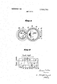
- FIG. 1 is a cross-sectional side view of an embodiment of .the percussion device of the present invention in which the DESCRIPTION OF A PREFERRED EMBODIMENT
- cylinder block 1 resembles a figure eight in cross section (FIG. 3) and it is provided with pump cylinder 12 slidably housing pump-piston 11 and tool cylinder 22 slidably housing free-piston 21. These cylinders are disposed parallel to each other. Upper end 12a of pump cylinder 12 is sealed by head cover 13 and upper end 22a of tool cylinder 22 is sealed by head cover 23. These upper ends are maintained at substantially the same height.
- Lower end 2212 of tool cylinder 22 sealed by cover 24 is positioned below lower end 1212 of pump cylinder 12 sealed by crankcase M.
- the interiors of both cylinders 12 and 22 communicate with each other at the upper and lower portions thereof through upper and lower openings 3 and 4 which are provided in wall portion 2 of the cylinder block 1, which portion separates the cylinders 12 and 22 from each other.
- Upper face 3a of upper opening 3 is positioned some what lower than upper end 22a of tool cylinder 22 and thus upper air cushion chamber 25 is formed beneath head cover 23 when the head of free-piston 21 passes above the upper face 3a of upper opening 3.
- the volume of chamber 25 is very small because the distance between upper end 22a of tool cylinder 22 and upper face 3a of upper opening 3 is short.
- the upper face of opening 3 inclines upwardly to form face 3' as shown in FIG. 1.
- the head of pump-piston 11 may be provided with downwardly inclined head surface 11 as shown in FIG. 1. Inclined face 3 of opening 3 and/or inclined head surface 11' ensures the opening 3 is never closed completely even when pump-piston 11 reaches its upper dead point.
- the diameter of upper opening 3 is selected in such a way that the lower ends of pistons 11 and 21 at their respective upper dead points are always below lower face 3b of upper opening 3 (FIG. 1).
- lower face 4b of lower opening 4 corresponds substantially to lower end 12b of pump cylinder 12 and therefore it is positioned far above lower end 22 b of tool cylinder 22. With this positioning, when the lower end of the free-piston 21 continues downward beyond the position of lower end face 4b of lower opening 4, lower air cushion chamber 26 of very large volume is formed above cover 24 within the tool cylinder.
- the vertical width of the lower opening 4 is made larger than that of upper opening 3 so that, even though there is a large difference in position between lower end 12b of the pump cylinder and lower end 22b of the tool cylinder, the heads of both pump-piston 11 and free-piston 21 at their lower dead points are positioned below upper face 4a of lower opening 4 thus opening the top part 4' of lower opening 4 (FIG. 2).
- this is a significant point in that it allows the pistons 11 and 21 to serve as a slide valve for reversing the positive and negative pressure conditions in the upper and lower chambers in tool cylinder 21.
- the vertical width of upper opening 3 is made shorter than that of lower opening 4 because of the necessity of making the area of upper opening 3 smaller and the area of lower opening 4 larger. Why this necessity exists will be explained hereinafter.
- crankcase 14 supports crank 15 which is driven by external power transmitted through end portion 16 projecting from airtight crank case 14.
- Crank 15 is rotated at a constant velocity (e.g. at a given velocity between 100 and 1200 r.p.m.).
- crank 15 drives the pump-piston 11 reciprocally in the conventional manner through connecting rod 17.
- Shocker 27 which is struck by free-piston 21 on its downward work stroke is mounted slidable in its axial direction on cover 24 which further has mounted thereupon stay 29 which supports chisel 28 which indirectly through shocker 27 receives the impact force from free-piston 21.
- cylinder block 1 which includes the pump cylinder block and the tool cylinder block can be suitable modified, that the driving power to rotate crank 15 may be supplied from an internal combustion engine, a fluid pressure motor or an electric motor, and that shocker 27 may be done away with so that free-piston 21 directly strikes the shank of chisel 28.
- the lower opening 4 has been described as being divided into two parts, these of course may be combined into one opening if there is no adverse effect on the strength of wall portion 2 of cylinder block 1.
- pump-piston l1 regularly and alternately performs first and upward stroke wherein the air in the upper chamber of pump cylinder 12 is compressed and a negative pressure is created in the lower chamber, and next a downward stroke wherein the air in the lower chamber is compressed and a negative pressure is created in the upper chamber.
- tool cylinder 22 which communicates with pump cylinder 12 through the upper and lower openings 3 and 4
- the pressure is respectively positive and negative in the upper and lower chambers during the upward stroke of pumppiston 11 and respectively negative and positive during the downward stroke.
- the free-piston is forced to move downward when the pressure is positive in the upper chamber and negative in the lower and completes its work stroke by hitting shocker 27.
- the terms upper chamber and lower chamber refer to the spaces in the cylinder above and below the piston which separates them in such a manner that when the volume one of them is increased by the movement of the piston, the other is decreased correspondingly.
- the chambers of the cylinders 12 and 22 are separated respectively by the pistons 11 and 21.
- Free-piston 21 compresses the large volume of air in air cushion chamber 26 as it travels downward reaching its lower dead point. At this point the top of free-piston 21 hasmoved below top part 4' of lower opening 4 connecting the upper chamber of tool cylinder 22 and the lower chamber of pump cylinder 11 and thereby allowing the positive pressure in the upper chamber of the tool cylinder which performed the work stroke to escape to the lower chamber of the pump cylinder which is under negative pressure FIG. 4b.
- the pump-piston travels downward compressing the air released from the upper chamber of the tool cylinder into the lower chamber of the pump cylinder.
- the compressed air in the lower chamber of the pump cylinder exerts through the large lower opening 4 a force which tends to raise the freepiston.
- FIG. 4b shows the pumppiston on the downward stroke from the upper dead point at the position where the driving means has advanced 60".
- FIG. 4c shows the situation after another 60 from the preceding condition. At this time, free-piston 21 is on its return stroke being acted upon by the low positive pressure below and the negative pressure above.
- the free-piston By the time the pump-piston 11 reaches it lower dead point, the free-piston has generally already closed the upper opening 3 and sealed upper buffer chamber 25 of the tool cylinder with its head. Accordingly, the free-piston compresses the air in upper buffer chamber 25 as it thereafter continues on its return stroke moving upward to its upper dead point by its own inertia. Hence the velocity of the free-piston is lowered considerably.
- the free-piston compresses the air in the buffer chamber 25 and reaches its upper dead point. Since bufier chamber 25 has less volume than lower bufier chamber 26, the compressed air in chamber 25 merely prevents the impingement of the piston head onto head cover 23 and does not have sufficient cushioning effect to force the free-piston downward. And the ever increasing pressure in the upper chamber of the pump cylinder acts as a side pressure upon the free-piston through upper opening 3 and assists the free-piston in its tendency to remain near the upper dead point at its residual moment (FIG. 4f).
- the illustrated embodiment can modified and a percussion device capable of producing an intense percussion force and workable with minimized noise without any leakage of the medium air may be obtained by designing the pump cylinder in such a way that its diameter is larger than that of the tool cylinder and that the air volume to be exhausted to the tool cylinder by the action of the pumppiston is made larger by -30 percent than that of the freepiston so that the free-piston is actuated with a sufficient volume of excess air, by determining the rotation of the crank of the air pump according to the massof the free-piston, the
- a free-piston type percussion device with air pump comprising:
- an air pump cylinder which slidably supports a piston therein, said piston being driven reciprocally up and down in a regular manner by a rotating power source of constant velocity;
- a tool cylinder housing the said free-piston which on its downward work stroke supplies an impart force to a chisel;
- upper and lower opening means for connecting the internal cavities of said cylinders near their tops and bottoms;
- an upper buffer means of small volume provided in the upper tportion of said tool cylinder by gositionin the upper ace of said upper opening sligh y elow the ead cover of said tool cylinder, said buffer means preventing said free-piston from striking said cylinder head cover at its upper dead point;
- a lower buffer means of large volume provided at the lower portion of said tool cylinder by positioning the lower face of said lower opening far above the lower end of said tool cylinder, saidlower buffer rebounding said free-piston after it strikes said
Landscapes
- Engineering & Computer Science (AREA)
- Mechanical Engineering (AREA)
- Percussive Tools And Related Accessories (AREA)
Applications Claiming Priority (1)
| Application Number | Priority Date | Filing Date | Title |
|---|---|---|---|
| JP1925669 | 1969-03-15 |
Publications (1)
| Publication Number | Publication Date |
|---|---|
| US3568780A true US3568780A (en) | 1971-03-09 |
Family
ID=11994334
Family Applications (1)
| Application Number | Title | Priority Date | Filing Date |
|---|---|---|---|
| US843669A Expired - Lifetime US3568780A (en) | 1969-03-15 | 1969-07-22 | Free-piston-type percussion device with air pump |
Country Status (4)
| Country | Link |
|---|---|
| US (1) | US3568780A (de) |
| CH (1) | CH497950A (de) |
| FR (1) | FR2031147A5 (de) |
| GB (1) | GB1243472A (de) |
Cited By (15)
| Publication number | Priority date | Publication date | Assignee | Title |
|---|---|---|---|---|
| US3835935A (en) * | 1973-03-19 | 1974-09-17 | Black & Decker Mfg Co | Idling system for power hammer |
| US3878902A (en) * | 1972-04-03 | 1975-04-22 | Susumu Matsuo | Impact tool |
| US20080190988A1 (en) * | 2007-02-09 | 2008-08-14 | Christopher Pedicini | Fastener Driving Apparatus |
| US20100213235A1 (en) * | 2009-02-25 | 2010-08-26 | Christopher Pedicini | Fastener Driving Apparatus |
| US20110108600A1 (en) * | 2009-11-11 | 2011-05-12 | Christopher Pedicini | Fastener Driving Apparatus |
| US8079504B1 (en) * | 2010-11-04 | 2011-12-20 | Tricord Solutions, Inc. | Fastener driving apparatus |
| US20120286014A1 (en) * | 2011-05-11 | 2012-11-15 | Christopher Pedicini | Fastener Driving Apparatus |
| CN103894980A (zh) * | 2012-12-24 | 2014-07-02 | 苏州宝时得电动工具有限公司 | 电动冲击工具 |
| US10525577B2 (en) * | 2016-11-25 | 2020-01-07 | Nanjing Chervon Industry Co., Ltd. | Power tool |
| US10814468B2 (en) | 2017-10-20 | 2020-10-27 | Milwaukee Electric Tool Corporation | Percussion tool |
| US20200406439A1 (en) * | 2016-08-31 | 2020-12-31 | Koki Holdings Co., Ltd. | Driver, pressure regulator and driving unit |
| US10926393B2 (en) | 2018-01-26 | 2021-02-23 | Milwaukee Electric Tool Corporation | Percussion tool |
| US11110577B2 (en) * | 2017-11-16 | 2021-09-07 | Milwaukee Electric Tool Corporation | Pneumatic fastener driver |
| US20220009067A1 (en) * | 2020-07-07 | 2022-01-13 | Techtronic Cordless Gp | Powered fastener driver |
| US11850714B2 (en) | 2021-07-16 | 2023-12-26 | Techtronic Cordless Gp | Powered fastener driver |
Families Citing this family (1)
| Publication number | Priority date | Publication date | Assignee | Title |
|---|---|---|---|---|
| DE102011078628A1 (de) * | 2011-07-05 | 2013-01-10 | Robert Bosch Gmbh | chlagwerkvorrichtung |
Citations (2)
| Publication number | Priority date | Publication date | Assignee | Title |
|---|---|---|---|---|
| US1196040A (en) * | 1913-02-25 | 1916-08-29 | smith | |
| US1319975A (en) * | 1919-10-28 | William a |
-
1969
- 1969-07-18 GB GB36370/69A patent/GB1243472A/en not_active Expired
- 1969-07-22 US US843669A patent/US3568780A/en not_active Expired - Lifetime
- 1969-08-25 CH CH1286769A patent/CH497950A/de not_active IP Right Cessation
-
1970
- 1970-01-16 FR FR7001598A patent/FR2031147A5/fr not_active Expired
Patent Citations (2)
| Publication number | Priority date | Publication date | Assignee | Title |
|---|---|---|---|---|
| US1319975A (en) * | 1919-10-28 | William a | ||
| US1196040A (en) * | 1913-02-25 | 1916-08-29 | smith |
Cited By (33)
| Publication number | Priority date | Publication date | Assignee | Title |
|---|---|---|---|---|
| US3878902A (en) * | 1972-04-03 | 1975-04-22 | Susumu Matsuo | Impact tool |
| US3835935A (en) * | 1973-03-19 | 1974-09-17 | Black & Decker Mfg Co | Idling system for power hammer |
| US20080190988A1 (en) * | 2007-02-09 | 2008-08-14 | Christopher Pedicini | Fastener Driving Apparatus |
| US8875969B2 (en) * | 2007-02-09 | 2014-11-04 | Tricord Solutions, Inc. | Fastener driving apparatus |
| USRE44001E1 (en) * | 2009-02-25 | 2013-02-19 | Tricord Solutions, Inc. | Fastener driving apparatus |
| US20100213235A1 (en) * | 2009-02-25 | 2010-08-26 | Christopher Pedicini | Fastener Driving Apparatus |
| US7793811B1 (en) * | 2009-02-25 | 2010-09-14 | Tricord Solutions, Inc. | Fastener driving apparatus |
| US8523035B2 (en) * | 2009-11-11 | 2013-09-03 | Tricord Solutions, Inc. | Fastener driving apparatus |
| US20110108600A1 (en) * | 2009-11-11 | 2011-05-12 | Christopher Pedicini | Fastener Driving Apparatus |
| US8079504B1 (en) * | 2010-11-04 | 2011-12-20 | Tricord Solutions, Inc. | Fastener driving apparatus |
| US20120286014A1 (en) * | 2011-05-11 | 2012-11-15 | Christopher Pedicini | Fastener Driving Apparatus |
| US8800834B2 (en) * | 2011-05-11 | 2014-08-12 | Tricord Solutions, Inc. | Fastener driving apparatus |
| CN103894980A (zh) * | 2012-12-24 | 2014-07-02 | 苏州宝时得电动工具有限公司 | 电动冲击工具 |
| CN103894980B (zh) * | 2012-12-24 | 2016-03-16 | 苏州宝时得电动工具有限公司 | 电动冲击工具 |
| US20200406439A1 (en) * | 2016-08-31 | 2020-12-31 | Koki Holdings Co., Ltd. | Driver, pressure regulator and driving unit |
| US11945083B2 (en) * | 2016-08-31 | 2024-04-02 | Koki Holdings Co., Ltd. | Driver, pressure regulator and driving unit |
| US10525577B2 (en) * | 2016-11-25 | 2020-01-07 | Nanjing Chervon Industry Co., Ltd. | Power tool |
| US11633843B2 (en) | 2017-10-20 | 2023-04-25 | Milwaukee Electric Tool Corporation | Percussion tool |
| US10814468B2 (en) | 2017-10-20 | 2020-10-27 | Milwaukee Electric Tool Corporation | Percussion tool |
| US20210370487A1 (en) * | 2017-11-16 | 2021-12-02 | Milwaukee Electric Tool Corporation | Pneumatic fastener driver |
| US11110577B2 (en) * | 2017-11-16 | 2021-09-07 | Milwaukee Electric Tool Corporation | Pneumatic fastener driver |
| US12544894B2 (en) | 2017-11-16 | 2026-02-10 | Milwaukee Electric Tool Corporation | Pneumatic fastener driver |
| US11897106B2 (en) * | 2017-11-16 | 2024-02-13 | Milwaukee Electric Tool Corporation | Pneumatic fastener driver |
| US11141850B2 (en) | 2018-01-26 | 2021-10-12 | Milwaukee Electric Tool Corporation | Percussion tool |
| US11203105B2 (en) | 2018-01-26 | 2021-12-21 | Milwaukee Electric Tool Corporation | Percussion tool |
| US11059155B2 (en) | 2018-01-26 | 2021-07-13 | Milwaukee Electric Tool Corporation | Percussion tool |
| US10926393B2 (en) | 2018-01-26 | 2021-02-23 | Milwaukee Electric Tool Corporation | Percussion tool |
| US11759935B2 (en) | 2018-01-26 | 2023-09-19 | Milwaukee Electric Tool Corporation | Percussion tool |
| US12472613B2 (en) | 2018-01-26 | 2025-11-18 | Milwaukee Electric Tool Corporation | Percussion tool |
| US11865687B2 (en) | 2018-01-26 | 2024-01-09 | Milwaukee Electric Tool Corporation | Percussion tool |
| US20220009067A1 (en) * | 2020-07-07 | 2022-01-13 | Techtronic Cordless Gp | Powered fastener driver |
| US11819989B2 (en) * | 2020-07-07 | 2023-11-21 | Techtronic Cordless Gp | Powered fastener driver |
| US11850714B2 (en) | 2021-07-16 | 2023-12-26 | Techtronic Cordless Gp | Powered fastener driver |
Also Published As
| Publication number | Publication date |
|---|---|
| FR2031147A5 (de) | 1970-11-13 |
| CH497950A (de) | 1970-10-31 |
| GB1243472A (en) | 1971-08-18 |
Similar Documents
| Publication | Publication Date | Title |
|---|---|---|
| US3568780A (en) | Free-piston-type percussion device with air pump | |
| US3878902A (en) | Impact tool | |
| US3821992A (en) | Impact device using a gas as its medium | |
| US4932479A (en) | Vacuum-compression type percussion power tool with a pumping chamber | |
| EP0661140A1 (de) | Eintreibewerkzeug für Befestigungsmittel | |
| US3559751A (en) | Percussion device | |
| US5161623A (en) | Percussion device | |
| SU1052627A1 (ru) | Машина ударного действи | |
| KR100956079B1 (ko) | 저소음형 유압 브레이커 | |
| US3754396A (en) | Impacting device | |
| US3511325A (en) | Device for extracting piles or the like | |
| US1382821A (en) | Power-hammer | |
| US3974885A (en) | Pneumatic percussive power tool | |
| KR20180028138A (ko) | 고하중 공압 항타기 | |
| CN112746638A (zh) | 一种压力自动反馈式减震节能型液压锤 | |
| JPS5842352B2 (ja) | ハンマ−キコウニクミコマレル ハンマ−ピストンノウンドウオゲンスイスルタメノ ホウホウオヨビハンマ−キコウ | |
| US3834469A (en) | Internal combustion operated hammer | |
| CN2687229Y (zh) | 氮气式液压破碎器 | |
| KR20090012199U (ko) | 저소음형 유압 브레이커 | |
| IE37177B1 (en) | Percussion apparatus | |
| US1072358A (en) | Fluid-pressure-driven tool. | |
| US4161989A (en) | Reciprocating hydraulic motors | |
| SU1060459A1 (ru) | Машина ударного действи | |
| SU1279726A1 (ru) | Холодновысадочный автомат | |
| SU808597A1 (ru) | Сваебойный дизельный молот |