US3572657A - Water baffle - Google Patents
Water baffle Download PDFInfo
- Publication number
- US3572657A US3572657A US830256A US3572657DA US3572657A US 3572657 A US3572657 A US 3572657A US 830256 A US830256 A US 830256A US 3572657D A US3572657D A US 3572657DA US 3572657 A US3572657 A US 3572657A
- Authority
- US
- United States
- Prior art keywords
- region
- ducting
- water
- section
- blower
- Prior art date
- Legal status (The legal status is an assumption and is not a legal conclusion. Google has not performed a legal analysis and makes no representation as to the accuracy of the status listed.)
- Expired - Lifetime
Links
- XLYOFNOQVPJJNP-UHFFFAOYSA-N water Substances O XLYOFNOQVPJJNP-UHFFFAOYSA-N 0.000 title claims abstract description 59
- 230000005484 gravity Effects 0.000 claims description 5
- 239000007788 liquid Substances 0.000 claims description 5
- 239000012530 fluid Substances 0.000 claims description 2
- 239000003570 air Substances 0.000 description 30
- 238000001816 cooling Methods 0.000 description 11
- 125000004122 cyclic group Chemical group 0.000 description 2
- 230000017525 heat dissipation Effects 0.000 description 2
- 230000006872 improvement Effects 0.000 description 2
- 229910052751 metal Inorganic materials 0.000 description 2
- 238000005192 partition Methods 0.000 description 2
- 230000003068 static effect Effects 0.000 description 2
- 239000012080 ambient air Substances 0.000 description 1
- 238000006243 chemical reaction Methods 0.000 description 1
- 238000010276 construction Methods 0.000 description 1
- 238000011109 contamination Methods 0.000 description 1
- 238000001704 evaporation Methods 0.000 description 1
- 230000008020 evaporation Effects 0.000 description 1
- 230000005012 migration Effects 0.000 description 1
- 238000013508 migration Methods 0.000 description 1
- 239000003595 mist Substances 0.000 description 1
- 239000000203 mixture Substances 0.000 description 1
- 230000004048 modification Effects 0.000 description 1
- 238000012986 modification Methods 0.000 description 1
- 239000003507 refrigerant Substances 0.000 description 1
- 239000007921 spray Substances 0.000 description 1
- 238000011144 upstream manufacturing Methods 0.000 description 1
- 238000009834 vaporization Methods 0.000 description 1
- 230000008016 vaporization Effects 0.000 description 1
- 239000002351 wastewater Substances 0.000 description 1
- 239000003643 water by type Substances 0.000 description 1
Images

Classifications
-
- F—MECHANICAL ENGINEERING; LIGHTING; HEATING; WEAPONS; BLASTING
- F28—HEAT EXCHANGE IN GENERAL
- F28F—DETAILS OF HEAT-EXCHANGE AND HEAT-TRANSFER APPARATUS, OF GENERAL APPLICATION
- F28F25/00—Component parts of trickle coolers
- F28F25/02—Component parts of trickle coolers for distributing, circulating, and accumulating liquid
- F28F25/04—Distributing or accumulator troughs
-
- F—MECHANICAL ENGINEERING; LIGHTING; HEATING; WEAPONS; BLASTING
- F28—HEAT EXCHANGE IN GENERAL
- F28C—HEAT-EXCHANGE APPARATUS, NOT PROVIDED FOR IN ANOTHER SUBCLASS, IN WHICH THE HEAT-EXCHANGE MEDIA COME INTO DIRECT CONTACT WITHOUT CHEMICAL INTERACTION
- F28C1/00—Direct-contact trickle coolers, e.g. cooling towers
- F28C1/02—Direct-contact trickle coolers, e.g. cooling towers with counter-current only
-
- Y—GENERAL TAGGING OF NEW TECHNOLOGICAL DEVELOPMENTS; GENERAL TAGGING OF CROSS-SECTIONAL TECHNOLOGIES SPANNING OVER SEVERAL SECTIONS OF THE IPC; TECHNICAL SUBJECTS COVERED BY FORMER USPC CROSS-REFERENCE ART COLLECTIONS [XRACs] AND DIGESTS
- Y02—TECHNOLOGIES OR APPLICATIONS FOR MITIGATION OR ADAPTATION AGAINST CLIMATE CHANGE
- Y02B—CLIMATE CHANGE MITIGATION TECHNOLOGIES RELATED TO BUILDINGS, e.g. HOUSING, HOUSE APPLIANCES OR RELATED END-USER APPLICATIONS
- Y02B30/00—Energy efficient heating, ventilation or air conditioning [HVAC]
- Y02B30/70—Efficient control or regulation technologies, e.g. for control of refrigerant flow, motor or heating
Definitions
- ABSTRACT A blow-through evaporative heat exchange apparatus having a blower section with a wet deck section above it and water baffles on the air fan ducts to prevent water from entering the fans when the air system is not being used.
- WATER nxma This invention is an improvement in blowthrough counterflow evaporative heat exchange apparatus, for example of the type which is disclosed in U.S. Pat. No. 3,442,494.
- the maximum design cooling capacity of evaporative heat exchangers is based on a given heat load and ambient wet bulb temperature when the air moving device is in operation to drive counterflowing air through the units.
- Heat dissipation equipment is not always required to operate under maximum duty conditions. For example, the heat load may be reduced or the ambient temperature may be less thandesign or both may occur at the same time. Under these conditions it is common to operate the evaporative heat exchange equipment without the air moving device in operation.
- These shut-down periods may be of short duration or very long, depending upon how much the design conditions vary from maximum. During the shut-down period the only air circulation is that caused by convection currents or the falling waters.
- Another object of this invention is to prevent the flow of water into the fan ducting or fans of a blowthrough evaporative heat exchanger thus preventing icing of the fans so that they may be efficiently and safely started at intermittent intervals during cyclic operation even under subfreezing temperature conditions.
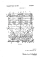
- FIG. 1 is a view in side elevation of a cooling tower of the type described in US. Pat. No. 3,442,494 incorporating a preferred embodiment of the present invention.
- FIG. 2 is a view in horizontal section taken along the line I Z-ZofFIG. 1.
- the cooling tower illustrated is comprised of an upper portion (in which the water is cooled) and a lower sump portion in the fonn of a V trough or container 11 in which the cooled water is collected.
- the upper portion 10 is rectangular in plan and is made up of a number of frames superimposed in registry to define four vertical sidewalls.
- the lower part of sump section 11 has two vertical opposite walls 12 and 13 in the plane of two of the sidewalls of the upper casing section and, between them, walls 14 and 15 disposed at 45 to the vertical, convergent and intersecting to define with the walls 12 and 13 the V-trough 11.
- Water to be cooled is supplied through manifold 16 and issues from various spray nozzles 17 to fall by gravity through a cooling region containing a wet deck surface section in the form of a large number of sheet metal elements '18 held by frames in horizontally and vertically spaced relation to present to the water, in total, a large surface area.
- the water, after flowing through the cooling area in contact with the various sheet metal elements 18 falls by gravity into the V-sump 11.
- the unit illustrated in the drawings is provided with centrifugal blowers which, by means to be hereinafter more fully described, cause air to flow upwardly between the surface elements 18 countercurrent to the gravitating water, whereby some of the water is evaporated and carried upwardly with the flowing air to leave the unit through mist eliminators 19 arranged at the top thereof.
- the heat extracted from the remaining water is, of course, carried with the exhausting air to the ambient atmosphere.
- the cool water falls to the sump.
- Makeup water enters through valve 20 opened by float 21 (see FIG. 2) and replaces the evaporated water and any waste water which has been drained to reduce contamination, etc.
- the cooled water is withdrawn from the sump 11 through a conduit 22 and delivered by a pump to a point of use such as the heat exchanger. After use, the water has taken on heat and must be returned to the cooling tower for cooling. This return is effected through conduit 26 leading to manifold 16.
- V-bottom of the sump reduce the amount of the water inventory, but it also permits locating of the blowers substantially within a vertical projection of the rectangular plan of the unit and because of its V-shape promotes static pressure increase in the sump section.
- Blower 29 and the two blowers behind it are keyed to a common drive shaft 32 to which there is also keyed a sheave 33 connected by multiple belts 34 to a drive sheave 35 of an electric motor 36.
- Motor 36 is mounted on a base plate 37 slidable in tracks 38. Connected to base plate 37 is a bracket 39 having a threaded stud 40 passing through it.
- This stud also passes through a U-section piece 41 which is the bottom piece of framework of the blower and motor support system.
- the stud 40 is provided with nuts 42 by adjustment of which on the stud 40 the motor mount may be easily shifted and held to control the tension on belts
- An arrangement identical to that just described is provided for the blower 28 and the two blowers behind it. In this case the motor bears'numeral 44, the belt adjusting assembly 45, and belt sheave 46, the common drive shaft 47.
- centrifugal blowers such as blowers 28 and 29, are of the axial intake, radial discharge type.
- the individual blowers are spaced apart, and shaft bearings are located on each end of a group of blowers.
- each blower such as 28 and 29
- the outlet side of each blower, such as 28 and 29, is connected to air ducting which passes through the respective sloping wall 15, 14 of the pan section and terminates in a mouth lying nearly in a vertical plane but sloping slightly in a direction opposite to the slope of the respective wall 14 or 15 through which the ducting passes.
- the ducting associated with blower 29 includes a portion 58 lying wholly within the sump 11.
- Blower 28 is provided with a duct portion 57 within the sump.
- ducting portions 59 and 60 within the sump 11 serve the unnumbered two blowers which lie behind blower 29 and ducting portions 61 and 62 within the sump 11 serve the two unnumbered blowers which lie behind blower 2b as it is viewed in FIG. 1.
- each duct portion 58 to 62, inclusive is of progressively increasing cross-sectional area in the direction of airflow so that a considerable measure of conversion of velocity pressure to static pressure is accomplished between the cutoff of the blower and the mouth of the ducting system.
- each of the ducts 57 to 62, inclusive there is located a water baffle, these baffles bearing numerals 57a to 62a respectively and constituting exemplifications of the present invention.
- the baffles 57a to 620 extend for the width of the top of the respective ducting and each water baffle projects forward of the ducting mouth. Note too that each of the baffles 57a to 620 is so bent that the downstream edge thereof is lower than the upstream edge. See in this regard FIG. 1.
- baffles 57a to 62a are provided to deal with the problem which arises when the system is operated without counterflow air as is the case in cool weather or under other circumstances when the equipment is dealing with a low heat load. Under these conditions water is supplied as usual from the nozzles 17 but no air is blown from the ducts 57 to 62, inclusive. Unless baffles such as those which bear numerals 57a to 62a are used, water falling on the top wall of the ducting will flow by capillarity around the upper defining edge of the duct mouth, partially into the ducting space to form a source of drops.
- baffles permit the water to con tinue to run off the front of the discharge duct and mix with the high velocity airstream issuing therefrom. An angle or dam across the top of the ducting would not allow this water flow necessary to achieve design cooling capacity.
- the sump or pan section 11, as illustrated in FIG. 1, is centrally divided by a partition 69 which extends between walls 12 and 13 and from the top of the pan section downwardly somewhat below the water level of the sump.
- a partition 69 which extends between walls 12 and 13 and from the top of the pan section downwardly somewhat below the water level of the sump.
- an air-antientrainment baffle 70 which extends horizontally across the bottom of the sump above the level of outlet pipe 22.
- the plate 70 also functions to equalize the withdrawal of water from the sump 11, since it is tapered to present a wider opening for water passage on the end remote from the outlet.
- a strainer supported by appropriate brackets.
- a blowthrough evaporative heat exchanger including a blower, means defining a region for the introduction of air, means to gravitate water throughout substantially all of the cross section of said region, air guiding means extending from said blower into said re 'on, said guiding means including an upper wall in a position 0 be impinged upon by on the end of and extending below said water baffle being small in relation to the cross section of the air guiding means.
- a blowthrough evaporative heat exchanger including a blower, means defining a region for the introduction of air, means to gravitate water throughout the cross section of said region, ducting extending from said blower into said region in a position to be impinged upon by said water, said ducting including a water baffle extending from its upper wall and projecting beyond and below the end of said upper wall within said region, the area of said water baffle projecting below the end of said upper wall being small in relation to the cross section of the ducting.
- Evaporative heat exchange apparatus comprising a chamber, a region of said chamber having therein surface presenting means for receiving fluid to have heat evaporatively extracted therefrom, means above said region to flow liquid by gravity over said surface presenting means, means defining a V-section sump below said region to receive liquid falling from said surface presenting means, said sump having a wall inclined outwardly from the bottom and a vertical wall at least one of which is part of the sump-defining means, an air blower, ducting leading from the outlet of said blower through said inclined wall and terminating with its mouth facing said vertical wall, a water baffle extending from the upper wall of said ducting and projecting beyond said mouth and below the upper defining edge thereof, the area of said water baffle projecting below the end of said upper wall being small in relation to the cross section of the ducting.
- a blow-through evaporative heat exchanger including a blower, means defining a region for the introduction of air, means to gravitate water throughout substantially all of the cross section of said region, air guiding means extending from said blower into said region, said guiding means including an upper wall in a position to be impinged upon by said water, and awater baffle on the end of and extending below said upper wall, said water baffle being small in relation to the cross section of the air guiding means.
Landscapes
- Engineering & Computer Science (AREA)
- Mechanical Engineering (AREA)
- General Engineering & Computer Science (AREA)
- Physics & Mathematics (AREA)
- Thermal Sciences (AREA)
- Heat-Exchange Devices With Radiators And Conduit Assemblies (AREA)
Applications Claiming Priority (1)
| Application Number | Priority Date | Filing Date | Title |
|---|---|---|---|
| US83025669A | 1969-06-04 | 1969-06-04 |
Publications (1)
| Publication Number | Publication Date |
|---|---|
| US3572657A true US3572657A (en) | 1971-03-30 |
Family
ID=25256628
Family Applications (1)
| Application Number | Title | Priority Date | Filing Date |
|---|---|---|---|
| US830256A Expired - Lifetime US3572657A (en) | 1969-06-04 | 1969-06-04 | Water baffle |
Country Status (4)
| Country | Link |
|---|---|
| US (1) | US3572657A (fr) |
| BE (1) | BE751497A (fr) |
| CA (1) | CA918632A (fr) |
| ZA (1) | ZA703403B (fr) |
Cited By (16)
| Publication number | Priority date | Publication date | Assignee | Title |
|---|---|---|---|---|
| US4267130A (en) * | 1979-08-16 | 1981-05-12 | Curtis Harold D | Portable auxiliary cooling tower |
| US4708826A (en) * | 1985-03-06 | 1987-11-24 | Sharp Kabushiki Kaisha | Supersonic humidifier |
| US5663536A (en) * | 1995-10-10 | 1997-09-02 | Amsted Industries Incorporated | Sound attenuation assembly for air-cooling apparatus |
| US6574980B1 (en) | 2000-09-22 | 2003-06-10 | Baltimore Aircoil Company, Inc. | Circuiting arrangement for a closed circuit cooling tower |
| US20140076289A1 (en) * | 2012-09-14 | 2014-03-20 | Ford Global Technologies, Llc | Charge air cooler condensation dispersion element |
| US20170292789A1 (en) * | 2016-04-10 | 2017-10-12 | Global Heat Transfer Ulc | Heat exchanger unit |
| US10416008B2 (en) | 2016-04-10 | 2019-09-17 | Forum Us, Inc. | Monitored heat exchanger system |
| US10480820B2 (en) * | 2016-04-10 | 2019-11-19 | Forum Us, Inc. | Heat exchanger unit |
| US10502598B2 (en) | 2016-04-10 | 2019-12-10 | Forum Us, Inc. | Sensor assembly |
| US10533814B2 (en) | 2016-04-10 | 2020-01-14 | Forum Us, Inc. | Method for monitoring a heat exchanger unit |
| EP2284253B2 (fr) † | 1999-09-08 | 2020-05-27 | Levitronix Technologies, LLC | Bioréacteur |
| US10677543B2 (en) | 2017-08-31 | 2020-06-09 | Baltimore Aircoil Company, Inc. | Cooling tower |
| US10775117B2 (en) | 2016-09-30 | 2020-09-15 | Baltimore Aircoil Company | Water collection/deflection arrangements |
| US11098962B2 (en) | 2019-02-22 | 2021-08-24 | Forum Us, Inc. | Finless heat exchanger apparatus and methods |
| US11946667B2 (en) | 2019-06-18 | 2024-04-02 | Forum Us, Inc. | Noise suppresion vertical curtain apparatus for heat exchanger units |
| US20240115284A1 (en) * | 2017-02-03 | 2024-04-11 | Aggreko Llc | Cooling Tower |
Citations (9)
| Publication number | Priority date | Publication date | Assignee | Title |
|---|---|---|---|---|
| US585568A (en) * | 1897-06-29 | Apparatus for purifying air | ||
| US1975945A (en) * | 1932-08-22 | 1934-10-09 | James P Curry | Cooling unit for refrigerating systems |
| US1981989A (en) * | 1932-11-15 | 1934-11-27 | Henry E Byer | Countercurrent condenser |
| US2072096A (en) * | 1932-10-19 | 1937-03-02 | Bahnson Co | Cooling tower |
| US2147876A (en) * | 1937-08-14 | 1939-02-21 | Arnold W Baumann | Countercurrent condenser |
| US2916267A (en) * | 1956-10-12 | 1959-12-08 | Simpson Herbert Corp | Inlet shield for filter |
| US3137145A (en) * | 1962-10-19 | 1964-06-16 | Dunham Bush Inc | Refrigeration system and evaporating cooling units |
| US3437319A (en) * | 1968-05-20 | 1969-04-08 | Baltimore Aircoil Co Inc | Evaporative heat exchanger with airflow reversal baffle |
| US3442494A (en) * | 1968-02-16 | 1969-05-06 | Baltimore Aircoil Co Inc | Evaporative heat exchange apparatus |
-
1969
- 1969-06-04 US US830256A patent/US3572657A/en not_active Expired - Lifetime
-
1970
- 1970-05-14 CA CA082770A patent/CA918632A/en not_active Expired
- 1970-05-19 ZA ZA703403A patent/ZA703403B/xx unknown
- 1970-06-04 BE BE751497D patent/BE751497A/fr not_active IP Right Cessation
Patent Citations (9)
| Publication number | Priority date | Publication date | Assignee | Title |
|---|---|---|---|---|
| US585568A (en) * | 1897-06-29 | Apparatus for purifying air | ||
| US1975945A (en) * | 1932-08-22 | 1934-10-09 | James P Curry | Cooling unit for refrigerating systems |
| US2072096A (en) * | 1932-10-19 | 1937-03-02 | Bahnson Co | Cooling tower |
| US1981989A (en) * | 1932-11-15 | 1934-11-27 | Henry E Byer | Countercurrent condenser |
| US2147876A (en) * | 1937-08-14 | 1939-02-21 | Arnold W Baumann | Countercurrent condenser |
| US2916267A (en) * | 1956-10-12 | 1959-12-08 | Simpson Herbert Corp | Inlet shield for filter |
| US3137145A (en) * | 1962-10-19 | 1964-06-16 | Dunham Bush Inc | Refrigeration system and evaporating cooling units |
| US3442494A (en) * | 1968-02-16 | 1969-05-06 | Baltimore Aircoil Co Inc | Evaporative heat exchange apparatus |
| US3437319A (en) * | 1968-05-20 | 1969-04-08 | Baltimore Aircoil Co Inc | Evaporative heat exchanger with airflow reversal baffle |
Cited By (25)
| Publication number | Priority date | Publication date | Assignee | Title |
|---|---|---|---|---|
| US4267130A (en) * | 1979-08-16 | 1981-05-12 | Curtis Harold D | Portable auxiliary cooling tower |
| US4708826A (en) * | 1985-03-06 | 1987-11-24 | Sharp Kabushiki Kaisha | Supersonic humidifier |
| US5663536A (en) * | 1995-10-10 | 1997-09-02 | Amsted Industries Incorporated | Sound attenuation assembly for air-cooling apparatus |
| EP2284253B2 (fr) † | 1999-09-08 | 2020-05-27 | Levitronix Technologies, LLC | Bioréacteur |
| US6574980B1 (en) | 2000-09-22 | 2003-06-10 | Baltimore Aircoil Company, Inc. | Circuiting arrangement for a closed circuit cooling tower |
| US20140076289A1 (en) * | 2012-09-14 | 2014-03-20 | Ford Global Technologies, Llc | Charge air cooler condensation dispersion element |
| US10914229B2 (en) * | 2012-09-14 | 2021-02-09 | Ford Global Technologies, Llc | Charge air cooler condensation dispersion element |
| US10416008B2 (en) | 2016-04-10 | 2019-09-17 | Forum Us, Inc. | Monitored heat exchanger system |
| US10545002B2 (en) | 2016-04-10 | 2020-01-28 | Forum Us, Inc. | Method for monitoring a heat exchanger unit |
| US10502598B2 (en) | 2016-04-10 | 2019-12-10 | Forum Us, Inc. | Sensor assembly |
| US10514205B2 (en) * | 2016-04-10 | 2019-12-24 | Forum Us, Inc. | Heat exchanger unit |
| US10520220B2 (en) | 2016-04-10 | 2019-12-31 | Forum Us, Inc. | Heat exchanger unit |
| US10533814B2 (en) | 2016-04-10 | 2020-01-14 | Forum Us, Inc. | Method for monitoring a heat exchanger unit |
| US10533881B2 (en) | 2016-04-10 | 2020-01-14 | Forum Us, Inc. | Airflow sensor assembly for monitored heat exchanger system |
| US20170292789A1 (en) * | 2016-04-10 | 2017-10-12 | Global Heat Transfer Ulc | Heat exchanger unit |
| US10480820B2 (en) * | 2016-04-10 | 2019-11-19 | Forum Us, Inc. | Heat exchanger unit |
| US10502597B2 (en) | 2016-04-10 | 2019-12-10 | Forum Us, Inc. | Monitored heat exchanger system |
| US10775117B2 (en) | 2016-09-30 | 2020-09-15 | Baltimore Aircoil Company | Water collection/deflection arrangements |
| US11255620B2 (en) | 2016-09-30 | 2022-02-22 | Baltimore Aircoil Company, Inc. | Water collection/deflection arrangement |
| US12419661B2 (en) * | 2017-02-03 | 2025-09-23 | Aggreko, Llc | Cooling tower |
| US20240115284A1 (en) * | 2017-02-03 | 2024-04-11 | Aggreko Llc | Cooling Tower |
| US10677543B2 (en) | 2017-08-31 | 2020-06-09 | Baltimore Aircoil Company, Inc. | Cooling tower |
| US11248859B2 (en) | 2017-08-31 | 2022-02-15 | Baltimore Aircoil Company, Inc. | Water collection arrangement |
| US11098962B2 (en) | 2019-02-22 | 2021-08-24 | Forum Us, Inc. | Finless heat exchanger apparatus and methods |
| US11946667B2 (en) | 2019-06-18 | 2024-04-02 | Forum Us, Inc. | Noise suppresion vertical curtain apparatus for heat exchanger units |
Also Published As
| Publication number | Publication date |
|---|---|
| ZA703403B (en) | 1971-01-27 |
| BE751497A (fr) | 1970-11-16 |
| CA918632A (en) | 1973-01-09 |
Similar Documents
| Publication | Publication Date | Title |
|---|---|---|
| US3572657A (en) | Water baffle | |
| US3290025A (en) | Trough system for evaporative heat exchangers | |
| US3437319A (en) | Evaporative heat exchanger with airflow reversal baffle | |
| US8622372B2 (en) | Fan cooling tower design and method | |
| US3784171A (en) | Evaporative heat exchange apparatus | |
| EP0057132B1 (fr) | Echangeur de chaleur à évaporation forcée | |
| US2971750A (en) | Evaporative cooling tower and the like | |
| US3899553A (en) | Cooling tower plume control | |
| US2941382A (en) | Condensate disposal means for selfcontained air conditioners | |
| US3442494A (en) | Evaporative heat exchange apparatus | |
| US2143628A (en) | Air conditioning apparatus | |
| US2311155A (en) | Heat exchange apparatus | |
| US2609888A (en) | Liquid-gas contact apparatus | |
| US10132569B2 (en) | Hybrid fluid cooler with extended intermediate basin nozzles | |
| US3575387A (en) | Air control damper for evaporative heat exchangers | |
| US1948980A (en) | Cooling tower | |
| US3385352A (en) | Evaporative heat exchanger | |
| US2778203A (en) | Air conditioning system having a cooling tower or the like | |
| US2854090A (en) | Crossflow cooling tower | |
| US2841369A (en) | Evaporative condenser apparatus and liquid disperser unit therefor | |
| US3165902A (en) | Water tower | |
| GB1220884A (en) | Evaporative heat exchange apparatus | |
| US20250354757A1 (en) | Industrial cooling system to control the water temperature of the process using a hybrid of air-cooled and water-cooled phases | |
| US2136003A (en) | Spray eliminator | |
| US3137145A (en) | Refrigeration system and evaporating cooling units |
Legal Events
| Date | Code | Title | Description |
|---|---|---|---|
| AS | Assignment |
Owner name: FIRST NATIONAL BAK OF CHICAGO, THE,ILLINOIS Free format text: SECURITY INTEREST;ASSIGNOR:BALTIMORE AIRCOIL COMPANY, INC., A CORP. OF DE.;REEL/FRAME:004520/0644 Effective date: 19860304 Owner name: FIRST NATIONAL BAK OF CHICAGO THE ONE FIRST NATION Free format text: SECURITY INTEREST;ASSIGNOR:BALTIMORE AIRCOIL COMPANY, INC., A CORP. OF DE.;REEL/FRAME:004520/0644 Effective date: 19860304 |
|
| AS | Assignment |
Owner name: BALTIMORE AIRCOIL COMPANY, INC., MARYLAND Free format text: RELEASED BY SECURED PARTY;ASSIGNOR:FIRST NATIONAL BANK OF CHICAGO, THE;REEL/FRAME:005091/0567 Effective date: 19880831 |