US3621941A - Brake mechanism - Google Patents
Brake mechanism Download PDFInfo
- Publication number
- US3621941A US3621941A US887083A US3621941DA US3621941A US 3621941 A US3621941 A US 3621941A US 887083 A US887083 A US 887083A US 3621941D A US3621941D A US 3621941DA US 3621941 A US3621941 A US 3621941A
- Authority
- US
- United States
- Prior art keywords
- brake
- bellows
- truck
- actuator
- beams
- Prior art date
- Legal status (The legal status is an assumption and is not a legal conclusion. Google has not performed a legal analysis and makes no representation as to the accuracy of the status listed.)
- Expired - Lifetime
Links
Images



Classifications
-
- B—PERFORMING OPERATIONS; TRANSPORTING
- B60—VEHICLES IN GENERAL
- B60T—VEHICLE BRAKE CONTROL SYSTEMS OR PARTS THEREOF; BRAKE CONTROL SYSTEMS OR PARTS THEREOF, IN GENERAL; ARRANGEMENT OF BRAKING ELEMENTS ON VEHICLES IN GENERAL; PORTABLE DEVICES FOR PREVENTING UNWANTED MOVEMENT OF VEHICLES; VEHICLE MODIFICATIONS TO FACILITATE COOLING OF BRAKES
- B60T17/00—Component parts, details, or accessories of power brake systems not covered by groups B60T8/00, B60T13/00 or B60T15/00, or presenting other characteristic features
- B60T17/08—Brake cylinders other than ultimate actuators
- B60T17/081—Single service brake actuators
-
- B—PERFORMING OPERATIONS; TRANSPORTING
- B61—RAILWAYS
- B61H—BRAKES OR OTHER RETARDING DEVICES SPECIALLY ADAPTED FOR RAIL VEHICLES; ARRANGEMENT OR DISPOSITION THEREOF IN RAIL VEHICLES
- B61H13/00—Actuating rail-vehicle brakes
- B61H13/20—Transmitting mechanisms
- B61H13/24—Transmitting mechanisms for cars with two axles or bogies with two axles and braking cylinder(s) for each bogie, the mechanisms at each side being interconnected
Definitions
- An improved brake mechanism for a railway vehicle truck which may be mounted as shown in the various positions in the drawings and comprises one or more rein- ;forced rubber convolute actuators which replace the standard brake cylinders used in prior art mechanisms.
- the actuators are without sliding or moving air seals which may be affected by water or ice and require no periodic internal inspection and maintenance.
- This invention relates to a brake rigging for a railway vehicle truck and more particularly to a new and improved brake rigging for railway freight cars.
- Prior art freight car brake riggings generally consist of one or more air-actuated brake cylinders which are carried on the car body underside.
- the brake cylinders piston rods are connected to individual brakeshoes, located at each wheel, by means of a plurality of rods, levers and other miscellaneous hardware.
- composition brakeshoe for railway rolling stock made it desirable to find new types of brake rigging in order to use the higher friction coefficient of the composition shoe to the best advantage since smaller braking forces were needed for this type of brakeshoe.
- One new type of brake rigging is shown in the US. Pat. No. 2,958,398, issued to G. K. Newell on Nov. 1, 1960 and comprises a pair of brake cylinders mounted on one brake beam with push rods exerting a force on the other brake beam.
- Another object of the invention is to provide a new and novel use of a reinforced rubber convoluted actuator to provide a lightweight and low-cost brake rigging having varying braking characteristics when used as hereinafter described.
- Another object of the invention is to provide a new and novel brake rigging which requires less maintenance than conventional brake rigging due to the elimination of the sliding and moving air seals associated with conventional airbrake cylinders.
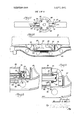
- FIG. 1 is a perspective view of a railway truck showing one form of the invention mounted on the brake beams;
- FIG. 2 is a plan view, of a brake rigging for a four-wheel, two-axle car truck showing one form of the invention
- FIG. 3 is a plan view, partially in section of the brake rigging shown in FIG. 2;
- FIG. 4 is a side elevational view, partially in section, of the brake rigging shown in FIG. 2;
- FIG. 5 is a sectional view taken along line 5-5 of FIG. 4;
- FIG. 6 is a plan view of a brake rigging for a four-wheel, two-axle car truck showing another form of the invention
- FIG. 7 is a view taken along line 7-7 ofFIG. 6;
- FIG. S is an enlarged plan view, partiallyin section, of the brake rigging shown in FIG. 6 showing the actuator in the unactuated position;
- FIG. 9 is an enlarged plan view, partially in section and similar to FIG. 8 showing the actuator in the actuated or expanded position
- FIG. H10 is a partial plan view, partially in section, of a brake rigging for a four-wheel, two-axle car truck showing still another form of the invention which may be used to provide varying braking characteristics;
- FIG. 11 is a sectional view taken along line 1lll of FIG. 10.
- a standard railway car truck which comprises a transversely extending truck bolster l2 resiliently mounted on a pair of truck side frames 14 by a plurality of springs (not shown in the drawings).
- the truck 10 contains a pair of axles 16 having wheels 18 mounted thereon, the axles being joumaled in the side frames 14 by well-known means.
- a pair of transversely extending brake beams 20 and 20a which are supported at the ends thereof by the truck 10 in a well-known manner for slidable movement of the brakeshoe 22 to a braking position against the wheels 18 of the truck 10.
- the air actuator 24 is in the form of a reinforced rubber convoluted bellows which is designed to replace the standard brake cylinders found on prior art railway car trucks which not only leaked compressed air but introduced considerable sliding friction in the cylinder which reduced the effective braking force applied to the brakeshoes 22.
- prior art brake cylinders due to the sliding and moving of the internal parts, were subjected to the effects of dirt, water and ice often encountered in railroad operations.
- the actuator 24 comprises a flexible reinforced convoluted bellows, shown generally at 28 which is sealed at its ends by a pair of circular end plates 30 and 32.
- the bellows 28 is formed of two convolutes 34 and 36 separated by a retaining ring 38 which acts to restrain the outward movements, in a controlled manner, of I the bellows 28 whenever air pressure is developed in the actuator by means of the air line 26, as shown in FIG. 4.
- the rubber bellows 28 contains reinforcing cords which are molded into the rubber as an aid to maintaining a fairly constant cross-sectional length of the convolutes 34 and 36 throughout the stroke of the actuator.
- the convolutes 34 and 36 tend to seek a circular form with the diameter of the effective area of the actuator 24 being defined by the distance between the radial centers of the convolutes.
- the retaining ring 38 which floats between the convolutes 34 and 36 permits the convolutes to seek and develop equal effective areas.
- the actuator 24 develops the force necessary to operate the train brakes in a controlled manner.
- the end plate 30 is restrained from horizontal movement by rods 42 to force the pair of brake beams 20 and 20a apart mits the brake beam 20 to have sufficient angularity to overcome unequal brakeshoe thickness without effecting the action of the bellows 28.
- the shims justment for specific wheel diameters may also be made by adding or removing an appropriate number of shims 48 from the end 47 of the push rods 42.
- the shims 48 are shown on the outside of the member 54 which is rigidly fastened to the brake beam 200 by means of a plurality of bolts 56 and nuts 58. It is apparent that the shims 48 may also be interchangeably contained on the end 47 of the push rods 42 within the member 54 in the opening 60, as shown in FIG. 3, without departing from the spirit and scope of the invention. Such interchangeability between the brake beams 20 and 20a to accommodate various wheel diameters by changing the location of the shims 48 from the position shown in H0. 2 and FIG. 4 to the position shown in FIG. 3.
- a plurality of pads 62 which serve as resilient means to permit lateral and angular motion between the brake beams 20 and 20a caused by unequal brakeshoe thickness.
- Sufficient stroke is provided for the actuator 24 to permit the railroad car to brake under normal conditions of wheel and brakeshoe wear and to allow the brakeshoes 22 to retract sufficiently from the wheels 18 so that the brakeshoes 22 may be changed when the brakes are not applied in the truck 10. From experimentation, it has been found that five-eighths inch are needed for release of the brakes with one-half inch required for wheel wear and seven-eighths inch required for brake shoe wear for each brake beam when l%-inch brakeshoes are used. As a result, a stroke of 4 inches is required for the actuator 24 to operate effectively as shown in Graph A.
- FIGS. 6 through 9 there is shown a modification of the basic invention which comprises the use of a pair of air actuators 24 mounted on the central portion of each of the brake beams for engagement with the bolster to thereby actuate the brake beams to a braking position.
- the air actuator 24 comprises the are constructed in the configuration shown and contain a pair of guide rails 66 having U-shaped wear clips 68 fastened on the inner sides thereof. Rigidly fastened to the end plate 32 is a member 70 which contains a plurality of guide fingers 72 having internal surfaces 74, 76 and 78 which are designed to slide on the guide rails 66.
- the adjusting means comprises a plurality of shims 84 rigidly held in place by means of a plurality of bolts 86 and nuts 88.
- the shims may be mounted either in the position shown in FIG. 8 or in the position shown in F IG. 9 is order to provide large latitude in adjusting of the distance between the bolster l2 and the brake beams 64.
- FIGS. 6 through 9 there is an actuator 24 mounted on each shown another modification of the invention wherein the air actuator 24 is mounted on the brake beam 20 with a plurality of push rods 42 extending through the truck bolster 12 and being mounted on the brake beam 20a similar to the mounting shown in FIG. 2.
- this modification there is interposed between the actuator 24 and the push rods 42, a means for varying the mechanical advantage of the actuator output force so as to decrease the braking force fade when the actuator stroke is increased and to reduce the high braking force obtained at a minimum actuator stroke. Be reducing the initial high braking force, a lighter construction car could be utilized without having excessive high braking ratios whenever the car is empty.
- the means for varying the actuator mechanical advantage is shown generally at 90 and comprises two pair of links 92 and 94 which are pivotally mounted to the push rods 42 by the pins 96 and to the web 100 of the brake beam 20 by meahs of the pin 102.
- the other ends of the links 94 are pivotably mounted to the frame 104 at its forked ends 106 by the pins 108.
- the frame 104 is positioned against the end plate 109 of the actuator 24, the actuator being similar in configuration to that shown in FIGS. 2 through 5 of the drawings.
- the means for restricting the lateral movement of the bellow ends to minimize bellows fatigue is shown generally at 110 and comprises a pair of guide rails 112 which are formed on the lower portion of the frame 104 in an outwardly extending manner.
- the rails 112 are designed to 'slide horizontally in a pair of U-shaped wear clips 114 which are retained in a recess 116 of the frame 118 by a plurality of pins 120.
- the frame 118 is rigidly fastened to the brake beam 20 by a plurality of bolts and nuts (not shown in the drawing).
- the frame 118 also contains a bottom surface 122 which serves as a stop for the other end of the actuator not connected to the frame 104.
- the ends 47 of the push rods 42 are fastened to the brake beam a in a manner similar to that shown in FIGS. 2 through 5 and as before described in the l specification. Accordingly, this embodiment also contains the resilient pads 62 as well as the shims 48 for the purposes before described.
- a. a pair of transversely extending, brakeshoe carrying, brake beams supported at the ends thereof by the truck for slidable movement to a braking position against the wheels of the truck;
- a resilient, air-actuated, convoluted bellows actuator mounted on the central portion of one of said brake beams;
- c. means, associated with one of said brake beams for restricting the lateral movement of the bellow ends relative to each other to minimize bellows fatigue and subsequent bellows failure;
- shim means associated with the other of said brake beams and said rods, for adjusting the horizontal distance between said brake beams to compensate for wheel and brake shoe wear and tolerance variations on the wheel and brake shoes to insure equal braking force application on each wheel of the truck.
- a transversely extending, brakeshoe carrying, brake beam member supported at the ends thereof by the truck for slidable movement of the brake beam and shoes to a braking position against the wheels of the truck;
Landscapes
- Engineering & Computer Science (AREA)
- Mechanical Engineering (AREA)
- Transportation (AREA)
- Braking Arrangements (AREA)
Abstract
Description
Claims (6)
Applications Claiming Priority (1)
| Application Number | Priority Date | Filing Date | Title |
|---|---|---|---|
| US88708369A | 1969-12-22 | 1969-12-22 |
Publications (1)
| Publication Number | Publication Date |
|---|---|
| US3621941A true US3621941A (en) | 1971-11-23 |
Family
ID=25390425
Family Applications (1)
| Application Number | Title | Priority Date | Filing Date |
|---|---|---|---|
| US887083A Expired - Lifetime US3621941A (en) | 1969-12-22 | 1969-12-22 | Brake mechanism |
Country Status (1)
| Country | Link |
|---|---|
| US (1) | US3621941A (en) |
Cited By (3)
| Publication number | Priority date | Publication date | Assignee | Title |
|---|---|---|---|---|
| US5000298A (en) * | 1989-09-18 | 1991-03-19 | Triax Tube Co. | Brake beam |
| US20040254693A1 (en) * | 2003-05-30 | 2004-12-16 | Parsons Keith D. | Fuel efficient airspeed trim |
| US20100258393A1 (en) * | 2009-04-09 | 2010-10-14 | Wabtec Holding Corp. | Brake Shoe Support Assembly and Method |
Citations (7)
| Publication number | Priority date | Publication date | Assignee | Title |
|---|---|---|---|---|
| US408982A (en) * | 1889-08-13 | lawrence | ||
| US1158177A (en) * | 1915-01-09 | 1915-10-26 | Johns H V Manville Co | Slack take-up for fluid-pressure-brake systems. |
| US2966963A (en) * | 1959-02-25 | 1961-01-03 | Westinghouse Air Brake Co | Brake rigging for railway car trucks |
| US3017959A (en) * | 1959-04-29 | 1962-01-23 | Westinghouse Air Brake Co | Foundation brake apparatus |
| US3037398A (en) * | 1958-06-30 | 1962-06-05 | Gen Electric | Brake slack adjustment |
| US3101814A (en) * | 1961-12-20 | 1963-08-27 | Westinghouse Air Brake Co | Slack adjusting mechanism for railway car brake apparatus |
| US3378108A (en) * | 1966-09-13 | 1968-04-16 | Westinghouse Air Brake Co | Fluid pressure operated brake apparatus for railway car trucks |
-
1969
- 1969-12-22 US US887083A patent/US3621941A/en not_active Expired - Lifetime
Patent Citations (7)
| Publication number | Priority date | Publication date | Assignee | Title |
|---|---|---|---|---|
| US408982A (en) * | 1889-08-13 | lawrence | ||
| US1158177A (en) * | 1915-01-09 | 1915-10-26 | Johns H V Manville Co | Slack take-up for fluid-pressure-brake systems. |
| US3037398A (en) * | 1958-06-30 | 1962-06-05 | Gen Electric | Brake slack adjustment |
| US2966963A (en) * | 1959-02-25 | 1961-01-03 | Westinghouse Air Brake Co | Brake rigging for railway car trucks |
| US3017959A (en) * | 1959-04-29 | 1962-01-23 | Westinghouse Air Brake Co | Foundation brake apparatus |
| US3101814A (en) * | 1961-12-20 | 1963-08-27 | Westinghouse Air Brake Co | Slack adjusting mechanism for railway car brake apparatus |
| US3378108A (en) * | 1966-09-13 | 1968-04-16 | Westinghouse Air Brake Co | Fluid pressure operated brake apparatus for railway car trucks |
Cited By (5)
| Publication number | Priority date | Publication date | Assignee | Title |
|---|---|---|---|---|
| US5000298A (en) * | 1989-09-18 | 1991-03-19 | Triax Tube Co. | Brake beam |
| US20040254693A1 (en) * | 2003-05-30 | 2004-12-16 | Parsons Keith D. | Fuel efficient airspeed trim |
| US7031811B2 (en) * | 2003-05-30 | 2006-04-18 | The Boeing Company | Fuel efficient airspeed trim |
| US20100258393A1 (en) * | 2009-04-09 | 2010-10-14 | Wabtec Holding Corp. | Brake Shoe Support Assembly and Method |
| US8360214B2 (en) | 2009-04-09 | 2013-01-29 | Wabtec Holding Corp. | Brake shoe support assembly and method |
Similar Documents
| Publication | Publication Date | Title |
|---|---|---|
| US4613016A (en) | Single-cylinder truck-mounted brake assembly | |
| US2034504A (en) | Suspension of railway cars and other vehicles | |
| US3378108A (en) | Fluid pressure operated brake apparatus for railway car trucks | |
| US3780837A (en) | Single cylinder truck-mounted brake | |
| US3499507A (en) | Railway car truck brake apparatus and adjusting means | |
| US3731766A (en) | Brake rigging for railway car trucks | |
| US2940554A (en) | Railway wheel tread brake unit | |
| US6932535B2 (en) | Pivoting joint for pivotally joining a brake head to a brake beam | |
| US4775035A (en) | Load compensating truck mounted brake system | |
| US3621941A (en) | Brake mechanism | |
| US4393960A (en) | Low noise railroad retarder brake shoe structure | |
| EP0879750B1 (en) | Improvements in bogie trucks for rail vehicles | |
| US3406791A (en) | Fluid pressure operated brake apparatus for railway car truck | |
| US4596311A (en) | Brake system | |
| US4039051A (en) | Disc brake construction, especially for rail vehicles | |
| US2357619A (en) | Pedestal snubber | |
| US3604539A (en) | Railway car brake mechanism | |
| US4258830A (en) | Railway brake system utilizing slack adjuster in compression | |
| USRE33207E (en) | Brake system | |
| US3624766A (en) | Railway vehicle wheel brake rigging | |
| US2357263A (en) | Brake mechanism | |
| US3280945A (en) | Tread brake assembly | |
| US3595348A (en) | Railway car truck brake apparatus | |
| US4434877A (en) | Truck-mounted brake system for railway cars | |
| US2966963A (en) | Brake rigging for railway car trucks |
Legal Events
| Date | Code | Title | Description |
|---|---|---|---|
| AS | Assignment |
Owner name: FIRST NATIONAL BANK OF CHICAGO, THE,ILLINOIS Free format text: SECURITY INTEREST;ASSIGNOR:AMSTED INDUSTRIES INCORPORATED;REEL/FRAME:004666/0778 Effective date: 19860227 Owner name: FIRST NATIONAL BANK OF CHICAGO, THE, ONE FIRST NAT Free format text: SECURITY INTEREST;ASSIGNOR:AMSTED INDUSTRIES INCORPORATED;REEL/FRAME:004666/0778 Effective date: 19860227 Owner name: FIRST NATIONAL BANK OF CHICAGO, THE, ILLINOIS Free format text: SECURITY INTEREST;ASSIGNOR:AMSTED INDUSTRIES INCORPORATED;REEL/FRAME:004666/0778 Effective date: 19860227 |
|
| AS | Assignment |
Owner name: AMSTED INDUSTRIES INCORPORATED, A CORP. OF DE., IL Free format text: RELEASED BY SECURED PARTY;ASSIGNOR:FIRST NATIONAL BANK OF CHICAGO, AS AGENT;REEL/FRAME:005070/0731 Effective date: 19880831 Owner name: AMSTED INDUSTRIES INCORPORATED, A CORP. OF DE., ILLINOIS Free format text: RELEASED BY SECURED PARTY;ASSIGNOR:FIRST NATIONAL BANK OF CHICAGO, AS AGENT;REEL/FRAME:005070/0731 Effective date: 19880831 |