US3649840A - Radiation-sensitive device utilizing a laser beam to measure the displacement of an object - Google Patents
Radiation-sensitive device utilizing a laser beam to measure the displacement of an object Download PDFInfo
- Publication number
- US3649840A US3649840A US19330A US3649840DA US3649840A US 3649840 A US3649840 A US 3649840A US 19330 A US19330 A US 19330A US 3649840D A US3649840D A US 3649840DA US 3649840 A US3649840 A US 3649840A
- Authority
- US
- United States
- Prior art keywords
- displacement
- cell
- measuring
- photoelectric cell
- amplifier
- Prior art date
- Legal status (The legal status is an assumption and is not a legal conclusion. Google has not performed a legal analysis and makes no representation as to the accuracy of the status listed.)
- Expired - Lifetime
Links
- 238000006073 displacement reaction Methods 0.000 title claims abstract description 64
- 230000005855 radiation Effects 0.000 title description 3
- 230000035945 sensitivity Effects 0.000 claims abstract description 23
- 238000005259 measurement Methods 0.000 claims abstract description 15
- 230000003321 amplification Effects 0.000 claims abstract description 12
- 238000003199 nucleic acid amplification method Methods 0.000 claims abstract description 12
- 238000010521 absorption reaction Methods 0.000 claims description 4
- 230000008878 coupling Effects 0.000 claims description 3
- 238000010168 coupling process Methods 0.000 claims description 3
- 238000005859 coupling reaction Methods 0.000 claims description 3
- 230000035699 permeability Effects 0.000 claims description 3
- 238000010408 sweeping Methods 0.000 claims description 2
- 230000004044 response Effects 0.000 abstract description 4
- 230000008859 change Effects 0.000 abstract description 3
- 230000008901 benefit Effects 0.000 description 4
- 238000005452 bending Methods 0.000 description 2
- 230000007423 decrease Effects 0.000 description 2
- 230000000694 effects Effects 0.000 description 2
- 238000010276 construction Methods 0.000 description 1
- 230000007613 environmental effect Effects 0.000 description 1
- 238000012986 modification Methods 0.000 description 1
- 230000004048 modification Effects 0.000 description 1
Images
Classifications
-
- G—PHYSICS
- G01—MEASURING; TESTING
- G01M—TESTING STATIC OR DYNAMIC BALANCE OF MACHINES OR STRUCTURES; TESTING OF STRUCTURES OR APPARATUS, NOT OTHERWISE PROVIDED FOR
- G01M5/00—Investigating the elasticity of structures, e.g. deflection of bridges or air-craft wings
- G01M5/0041—Investigating the elasticity of structures, e.g. deflection of bridges or air-craft wings by determining deflection or stress
-
- G—PHYSICS
- G01—MEASURING; TESTING
- G01B—MEASURING LENGTH, THICKNESS OR SIMILAR LINEAR DIMENSIONS; MEASURING ANGLES; MEASURING AREAS; MEASURING IRREGULARITIES OF SURFACES OR CONTOURS
- G01B11/00—Measuring arrangements characterised by the use of optical techniques
- G01B11/16—Measuring arrangements characterised by the use of optical techniques for measuring the deformation in a solid, e.g. optical strain gauge
-
- G—PHYSICS
- G01—MEASURING; TESTING
- G01D—MEASURING NOT SPECIALLY ADAPTED FOR A SPECIFIC VARIABLE; ARRANGEMENTS FOR MEASURING TWO OR MORE VARIABLES NOT COVERED IN A SINGLE OTHER SUBCLASS; TARIFF METERING APPARATUS; MEASURING OR TESTING NOT OTHERWISE PROVIDED FOR
- G01D5/00—Mechanical means for transferring the output of a sensing member; Means for converting the output of a sensing member to another variable where the form or nature of the sensing member does not constrain the means for converting; Transducers not specially adapted for a specific variable
- G01D5/26—Mechanical means for transferring the output of a sensing member; Means for converting the output of a sensing member to another variable where the form or nature of the sensing member does not constrain the means for converting; Transducers not specially adapted for a specific variable characterised by optical transfer means, i.e. using infrared, visible, or ultraviolet light
-
- G—PHYSICS
- G01—MEASURING; TESTING
- G01M—TESTING STATIC OR DYNAMIC BALANCE OF MACHINES OR STRUCTURES; TESTING OF STRUCTURES OR APPARATUS, NOT OTHERWISE PROVIDED FOR
- G01M5/00—Investigating the elasticity of structures, e.g. deflection of bridges or air-craft wings
- G01M5/0091—Investigating the elasticity of structures, e.g. deflection of bridges or air-craft wings by using electromagnetic excitation or detection
Definitions
- a source of a laser beam is positioned on a reference point, and the beam is directed [22] 1970 toward the photocell to generate an electrical signal in [211 App]. No.: 19,330 response to the position of the beam on the cell.
- the beam is fanned out along a path which intersects and crosses the cell, and accordingly displacement of the object causes a displace- [301 Forelgn Application Pnomy Dam ment of the cell which generates a change in the electrical out- Mar. 17, 1969 Germany ..P 19 133 99.4 put. in order to produce an electrical output signal which is free from fluctuations due to causes other than the displace- [52] U.S.
- a comparison photoelectric cell is disposed [51] Int. Cl. parallel to the measuring photocell, and the laser beam crosses Field Of Search 211 the comparison cell as well.
- the comparison cell produces a 356/167, 172 signal which is fed to an amplifier and which may be used as a reference to compare the magnitude of the output from the [56] Reierences Clted measuring photoelectric cell.
- the amplifier for the comparison cell may be self adjusting to produce a constant UNITED STATES PATENTS output and may be coupled to the amplifier at the output of 2,879,405 3/1959 Pankove ..250/211 the measuring cell to control the amplification factor thereof.
- the field of art to which this invention pertains is a means for measuring continuous displacements of objects and particularly of structural objects using a laser beam.
- the present invention relates to a device for measuring substantial displacements in the order of magnitude of several centimeters as well as for measuring considerably smaller displacements.
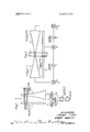
- FIG. 1 is a schematic illustrating the positioning of a comparison photoelectric cell and a measuring photoelectric cell side by side and showing the orientation of a fanned-out laser beam which crosses both of the photocells to generate separate output signals.
- FIG. 2 is an illustration of another embodiment of the present invention in which a pair of oppositely arranged measuring photocells are used in conjunction with a constant width comparison cell.
- the present invention relates to a device for measuring the displacement or shifting of an object using a laser beam mounted on a reference plane.
- a photoreceiving device is attached to the object to be measured and has a variable sensitivity so that relative motion between the photoreceiving device and the laser beam will generate changing electrical signals.
- Devices for the continuous measurement of shifting or displacement of structures are required for numerous uses. For instance, in the construction industry, it is often required to measure continuously the deformation of walls, bridge piers or the like. In taking such measurements, it is often impossible to find a reference level for the measurement since the ground and surrounding areas often deform with the structure being measured. This is principally true in the case of making load tests for bridge piers where measurements of deformation have to be made continuously over a period of several hours while the pier is under a certain load.
- Such measurements are primarily done optically.
- an observer watches the position of a mark on the object being measured from a place sufficiently far away to be free of deformations. This is often done with the help of a telescope.
- a telescope is often expensive due to the high cost of the expertise required in making these measurements.
- Prior devices have utilized laser beams for the purpose of controlling the position of a machine or the like. These devices, however, are not suitable for long period recording of the shifting or displacement of an object.
- One of the problems has been to find a means for dealing with fluctuations in the operation of laser beams which could distort readings over a period of time.
- prior devices have been capable of measuring only small displacements rather than displacements in the order of several centimeters which are possible by the present invention.
- the present invention provides an apparatus which is capable of making such measurements.
- a laser beam originates from a reference position and is directed onto a measuring photoelectric cell which is disposed to move with the shifting or deformation of the object being measured.
- the photoelectric cell has an absolute sensitivity which changes continuously in the direction in which the measuring is being accomplished. This sensitivity is brought about by a variation in the width of the cell from one end to the other.
- the nonlinearity of the photocell arrangement is required due to the unequal distribution of the radiation density of the fanned out laser beam.
- a constant width photoelectric cell may be used and a filter may be arranged between the cell and the source of the laser beam in such a way that the filter changes its permeability continuously in the measurement direction.
- the filter for instance, may be an absorption filter with the constant value of absorption increasing continuously from one end of the filter to the other.
- Such a filter arrangement has the advantage of producing increasing sensitivity of the cell without requiring increasing width. In this way, a much narrower photocell can be utilized.
- a comparison photoelectric cell may be arranged parallel to the measuring cell.
- the comparison cell may have a constant sensitivity along its length.
- the fanned-out laser beam is then caused to impinge simultaneously on both the comparison cell and the measuring cell.
- Both of the photoelectric cells may be arranged on the load side of a differential amplifier.
- the outputs of both of the photoelectric cells may be coupled to respective amplifiers.
- the comparison photocell may be coupled to an amplifier which is self adjusting and which provides a constant output signal.
- the output of this amplifier may then be used to control the amplification of the amplifier coupled to the output of the measuring photoelectric cell. In this way, a constant reference may be provided for the amplified measuring signal even though the level of amplification may be changed to suit the requirements of the system.
- a differential stage may be omitted in view of the cost of output of the comparison amplifier.
- a recorder may be used to provide a continuous record of the amount of deformation or shifting of the object being measured over a period of time.
- the recorder would simply be coupled to the output of the amplifiers from the respective photoelectric cells.
- a system according to the present invention can also be used to detect twistings or bendings of an object by utilizing a second measuring photoelectric cell having an absolute sensitivity which changes in the same direction as the sensitivity of the first measuring cell.
- a differential amplifier may be coupled to the output.
- a bending motion would produce a variation of the longitudinal shifting between the two measuring photoelectric cells such that their output signals would change unequally.
- a system according to the present invention may also be utilized advantageously to control machines or apparatus. It is possible to determine the nominal position of a machine and utilize increases and decreases of the output signal from the measuring cell to operate a control and return the machine to its nominal plane.
- two measuring photoelectric cells are to be provided having an absolute sensitivity which changes continuously in opposite directions such that the cells effectively increase in width from a center point between the cells.
- An amplifier is preferably arranged on the load side of each cell which can be adjusted by a constant output amplifier as already described.
- a comparison photoelectric cell may be provided, and this would extend the entire length of both of the measuring photoelectric cells so that only one automatically adjusting amplifier need be provided.
- the above arrangement can be expanded so that machines are guided along a straight line or the like.
- a laser beam can be utilized which produces two beams and wherein the receiver consists of two combined arrangements of measuring photoelectric cells which extend along one side of a right angle.
- Other arrangements may be proposed.
- FIG. I shows two photoelectric cells 1 and 2 having their longitudinal direction lined generally parallel to the measuring direction which is indicated by the double arrow 2a.
- the measuring photoelectric cell 2 has a photosensitive plane which widens continuously in the longitudinal direction.
- the width of the comparison photoelectric cell is constant over the entire length. Both cells are fixed to the object being measured.
- a laser beam 3 is provided from a suitable source which source is disposed on a reference plane.
- the beam 3 is fanned out as shown and crosses both the cells 1 and 2.
- the cells 1 and 2 will be displaced and signals S and S, will be generated from the cells. It is apparent that the signal S: will remain constant with the variations in relative position of the laser beam 3, while variations in the signal S will increase or decrease with the changing relative positions between the beam 3 and the widened cell 2.
- an automatically adjusted amplifier V is arranged on the load side of the comparison photoelectric cell.
- This amplifier has an amplification which changes automatically to produce a constant output signal S
- the amplifier V is then coupled to a control system a and from the system 4 to an amplifier V
- the amplifier V is coupled to the output of the measuring photoelectric cell 2 and has its amplification adjusted by the signal coming from the amplifier V
- the outputs of both of the amplifiers V and V are coupled to a differential amplifier 5.
- the differential amplifier 5 could be omitted in the arrangement shown in FIG. 1 due to the presence of the constant adjusting amplifier V and the coupling of the output of that amplifier to the further amplifier V
- the laser radiation may also be modulated to increase the sensitivity of operation. Also, modulation has the advantage of reducing the effects of daylight or other straight light from the environment. Such straight light can be suppressed in a modulated system by the use of selectively absorbing filters or the like.
- FIG. 2 a similar type arrangement is provided which may be used for the control of the movement of a machine along a plane.
- the photoreceiver which is attached to the machine contains two photoelectric cells 12 and 13 which are arranged to have increasing sensitivities in opposite directions from a common center point 13a.
- a comparison photoelectric cell is provided parallel to the two photoelectric cells 12 and 13 and has an output connected to an automatically adjusting amplifier V
- the amplifier V corresponds to the amplifier V in FIG. 1 and is coupled to further amplifiers V and V over circuits 14.
- a shifting or displacement of the laser beam 3 with respect to the load cells generates an output signal in either direction which can then be utilized to control the machine operations with respect to a given plane or line of movement.
- the relative motion between the beam and the cells is caused by the shifting of the photoelectric cells which are coupled in a suitable manner to the machine.
- the laser source is rigidly positioned on a reference plane at a distant point.
- Such a device as described above has the advantage that the continuous adjustment of the machine is possible and not simply an adjustment after a given deviation is exceeded.
- a similar receiver as shown in FIG. 2 both laterally and vertically and providing so-called cross fanned laser beams, an arrangement is provided for the control or guidance of a machine along a straight line.
- the present invention is not limited to the specific arrangements described above. Especially, it is not necessary that these controls be used to guide a machine along a plane or along a straight line but could also be used for different proportional controls corresponding to the shifting of the machine other than simply returning the machine to a nominal position.
- comparison photoelectric cell assures that the distance differences between the laser and the receiving arrangement do not have any effect on the system output. This is especially true in the case of moving machines being controlled whereby an overloading of the amplifiers could be accomplished when the machine is closest to the source of the laser energy.
- a system for continually measuring the amount of displacement of an object relative to a reference plane comprismg:
- said first measuring photoelectric cell having an absolute sensitivity which changes continuously in the direction of the displacement to be measured
- said laser beam being fanned out in a direction intersecting and crossing said photoelectric cell
- comparison photoelectric cell being arranged on said object substantially parallel to said measuring photoelectric cell, said comparison photoelectric cell having a substantially constant absolute sensitivity along its length
- a displacement measuring system in accordance with claim 2 wherein the increase in the width of the cell along the length thereof is nonlinear such that the output signal generated from the cell changes linearly with the sweeping of the beam along the length of the cell.
- a displacement system in accordance with claim 1 wherein a first self adjusting amplifier is coupled to the output of the comparison photoelectric cell, said self adjusting amplifier producing a substantially constant output, a further amplifier coupled to the output of the measuring photoelectric cell, and means coupling an output of said first amplifier to said further amplifier to control the amplification thereof.
- a displacement system in accordance with claim 1 wherein a second measuring photoelectric cell is provided oppositely of said first measuring photoelectric cell and has increasing sensitivity in a direction oppositely of the direction of increasing sensitivity of said first measuring photoelectric cell, whereby the displacement of a moving object along a plane can be determined relative to a fixed line of travel.
Landscapes
- Physics & Mathematics (AREA)
- General Physics & Mathematics (AREA)
- Engineering & Computer Science (AREA)
- Aviation & Aerospace Engineering (AREA)
- Electromagnetism (AREA)
- Length Measuring Devices By Optical Means (AREA)
Applications Claiming Priority (1)
| Application Number | Priority Date | Filing Date | Title |
|---|---|---|---|
| DE1913399A DE1913399C3 (de) | 1969-03-17 | 1969-03-17 | Anordnung zur kontinuierlichen Messung von Verschiebungen oder Verformungen mit Hilfe von Laserstrahlen |
Publications (1)
| Publication Number | Publication Date |
|---|---|
| US3649840A true US3649840A (en) | 1972-03-14 |
Family
ID=5728346
Family Applications (1)
| Application Number | Title | Priority Date | Filing Date |
|---|---|---|---|
| US19330A Expired - Lifetime US3649840A (en) | 1969-03-17 | 1970-03-13 | Radiation-sensitive device utilizing a laser beam to measure the displacement of an object |
Country Status (8)
| Country | Link |
|---|---|
| US (1) | US3649840A (de) |
| AU (1) | AU1261870A (de) |
| CH (1) | CH525466A (de) |
| DE (1) | DE1913399C3 (de) |
| FR (1) | FR2038901A5 (de) |
| GB (1) | GB1307014A (de) |
| NL (1) | NL7002861A (de) |
| SE (1) | SE360170B (de) |
Cited By (12)
| Publication number | Priority date | Publication date | Assignee | Title |
|---|---|---|---|---|
| US3937950A (en) * | 1973-04-11 | 1976-02-10 | Canon Kabushiki Kaisha | Focus defecting system |
| US3961178A (en) * | 1973-10-23 | 1976-06-01 | Canon Kabushiki Kaisha | Image sharpness detecting system and apparatus utilizing the same |
| US4019935A (en) * | 1975-05-14 | 1977-04-26 | Diamond International Corporation | Automatic feeding of labels for application to bottles or other containers |
| US4230940A (en) * | 1977-07-22 | 1980-10-28 | Tokyo Shibaura Denki Kabushiki Kaisha | Automatic focusing apparatus |
| US4320293A (en) * | 1978-08-30 | 1982-03-16 | Harold Guretzky | Angle-position transducer |
| DE3332463A1 (de) * | 1982-10-29 | 1984-05-03 | The Perkin-Elmer Corp., 06856 Norwalk, Conn. | Nichtabbildendes system zur feststellung des einfallswinkels einer strahlung |
| US4474468A (en) * | 1980-04-18 | 1984-10-02 | Hitachi, Ltd. | Method of and apparatus for measuring laser beam |
| US4731530A (en) * | 1986-04-21 | 1988-03-15 | Mikan Peter J | Joystick control having optical sensors |
| US4825157A (en) * | 1988-05-16 | 1989-04-25 | Mikan Peter J | Hall-effect controller |
| US5012086A (en) * | 1989-10-04 | 1991-04-30 | Barnard Timothy J | Optoelectronic pickup for stringed instruments |
| US5357106A (en) * | 1993-10-01 | 1994-10-18 | Xerox Corporation | Sensor for detecting beam position and start of scan position |
| WO2020083502A1 (en) * | 2018-10-26 | 2020-04-30 | KRUSEMARK, Steven Wayne | Rotary position detector |
Families Citing this family (9)
| Publication number | Priority date | Publication date | Assignee | Title |
|---|---|---|---|---|
| GB1542873A (en) * | 1976-01-30 | 1979-03-28 | Rca Corp | Digital transducer |
| DE2628796C3 (de) * | 1976-06-26 | 1981-12-10 | Karl Pfisterer Elektrotechnische Spezialartikel Gmbh & Co Kg, 7000 Stuttgart | Fernmeßgerät |
| AT360465B (de) * | 1979-03-14 | 1981-01-12 | Voest Alpine Ag | Einrichtung zur kontrolle der position einer streckenvortriebsmaschine |
| SE420352B (sv) * | 1980-01-21 | 1981-09-28 | Lars Stenmark | Optisk legesgivare |
| JPS5661413U (de) * | 1980-04-02 | 1981-05-25 | ||
| GB8531149D0 (en) * | 1985-12-18 | 1986-01-29 | Smiths Industries Plc | Optical transducers |
| DE3720294C1 (de) * | 1987-06-19 | 1988-09-08 | Messerschmitt Boelkow Blohm | Optoelektrischer Positionierungs-Abgriff |
| DE9100575U1 (de) * | 1991-01-22 | 1992-02-20 | Siemens AG, 8000 München | Vorrichtung zur Regelung der Sitzflächenhöhe insbesondere bei einem Fahrzeugsitz |
| DE102004039682A1 (de) | 2004-08-16 | 2006-03-30 | Siemens Ag | Anschlussvorrichtung für eine elektrische Maschine |
Citations (6)
| Publication number | Priority date | Publication date | Assignee | Title |
|---|---|---|---|---|
| US2879405A (en) * | 1953-06-29 | 1959-03-24 | Rca Corp | Semi-conductor photo-electric devices |
| US3087069A (en) * | 1959-08-12 | 1963-04-23 | Giannini Controls Corp | Radiation-controlled variable resistance |
| US3159750A (en) * | 1962-10-01 | 1964-12-01 | Eugene I Kazan | Photoelectric pressure transducer |
| US3193686A (en) * | 1963-05-07 | 1965-07-06 | Western Electric Co | Photosensitive detectors and methods utilizing photosensitive detectors for positioning articles |
| US3258601A (en) * | 1966-06-28 | Photosensitive variable resistance device | ||
| US3354311A (en) * | 1965-08-23 | 1967-11-21 | Boeing Co | Fringe movement detector including dual photocells |
-
1969
- 1969-03-17 DE DE1913399A patent/DE1913399C3/de not_active Expired
-
1970
- 1970-02-27 NL NL7002861A patent/NL7002861A/xx unknown
- 1970-03-06 CH CH331270A patent/CH525466A/de not_active IP Right Cessation
- 1970-03-13 US US19330A patent/US3649840A/en not_active Expired - Lifetime
- 1970-03-13 FR FR7009077A patent/FR2038901A5/fr not_active Expired
- 1970-03-16 AU AU12618/70A patent/AU1261870A/en not_active Expired
- 1970-03-16 GB GB1246970A patent/GB1307014A/en not_active Expired
- 1970-03-17 SE SE03567/70A patent/SE360170B/xx unknown
Patent Citations (6)
| Publication number | Priority date | Publication date | Assignee | Title |
|---|---|---|---|---|
| US3258601A (en) * | 1966-06-28 | Photosensitive variable resistance device | ||
| US2879405A (en) * | 1953-06-29 | 1959-03-24 | Rca Corp | Semi-conductor photo-electric devices |
| US3087069A (en) * | 1959-08-12 | 1963-04-23 | Giannini Controls Corp | Radiation-controlled variable resistance |
| US3159750A (en) * | 1962-10-01 | 1964-12-01 | Eugene I Kazan | Photoelectric pressure transducer |
| US3193686A (en) * | 1963-05-07 | 1965-07-06 | Western Electric Co | Photosensitive detectors and methods utilizing photosensitive detectors for positioning articles |
| US3354311A (en) * | 1965-08-23 | 1967-11-21 | Boeing Co | Fringe movement detector including dual photocells |
Cited By (13)
| Publication number | Priority date | Publication date | Assignee | Title |
|---|---|---|---|---|
| US3937950A (en) * | 1973-04-11 | 1976-02-10 | Canon Kabushiki Kaisha | Focus defecting system |
| US3961178A (en) * | 1973-10-23 | 1976-06-01 | Canon Kabushiki Kaisha | Image sharpness detecting system and apparatus utilizing the same |
| US4019935A (en) * | 1975-05-14 | 1977-04-26 | Diamond International Corporation | Automatic feeding of labels for application to bottles or other containers |
| US4230940A (en) * | 1977-07-22 | 1980-10-28 | Tokyo Shibaura Denki Kabushiki Kaisha | Automatic focusing apparatus |
| US4320293A (en) * | 1978-08-30 | 1982-03-16 | Harold Guretzky | Angle-position transducer |
| US4474468A (en) * | 1980-04-18 | 1984-10-02 | Hitachi, Ltd. | Method of and apparatus for measuring laser beam |
| DE3332463A1 (de) * | 1982-10-29 | 1984-05-03 | The Perkin-Elmer Corp., 06856 Norwalk, Conn. | Nichtabbildendes system zur feststellung des einfallswinkels einer strahlung |
| US4593187A (en) * | 1982-10-29 | 1986-06-03 | The Perkin-Elmer Corporation | Non-imaging illumination incidence angle detection system |
| US4731530A (en) * | 1986-04-21 | 1988-03-15 | Mikan Peter J | Joystick control having optical sensors |
| US4825157A (en) * | 1988-05-16 | 1989-04-25 | Mikan Peter J | Hall-effect controller |
| US5012086A (en) * | 1989-10-04 | 1991-04-30 | Barnard Timothy J | Optoelectronic pickup for stringed instruments |
| US5357106A (en) * | 1993-10-01 | 1994-10-18 | Xerox Corporation | Sensor for detecting beam position and start of scan position |
| WO2020083502A1 (en) * | 2018-10-26 | 2020-04-30 | KRUSEMARK, Steven Wayne | Rotary position detector |
Also Published As
| Publication number | Publication date |
|---|---|
| AU1261870A (en) | 1971-09-23 |
| GB1307014A (en) | 1973-02-14 |
| DE1913399A1 (de) | 1970-09-24 |
| NL7002861A (de) | 1970-09-21 |
| SE360170B (de) | 1973-09-17 |
| DE1913399C3 (de) | 1974-08-22 |
| FR2038901A5 (de) | 1971-01-08 |
| CH525466A (de) | 1972-07-15 |
| DE1913399B2 (de) | 1974-01-31 |
Similar Documents
| Publication | Publication Date | Title |
|---|---|---|
| US3649840A (en) | Radiation-sensitive device utilizing a laser beam to measure the displacement of an object | |
| US3679307A (en) | Non-contacting optical probe | |
| US5714763A (en) | Method and apparatus for optical alignment of a measuring head in an X-Y plane | |
| US3536405A (en) | Optical thickness gauge | |
| US4589286A (en) | Fused silica diaphragm module for high temperature pressure transducers | |
| ATE56537T1 (de) | Laengenmessvorrichtung nach dem zweistrahl-laser- interferometerprinzip. | |
| US4231662A (en) | Phase shift correction for displacement measuring systems using quadrature | |
| US4110049A (en) | Sun meter | |
| US3945730A (en) | Arrangement for measuring, checking and control of the position of chosen points of objects with respect to an optical aiming line | |
| CN106247992B (zh) | 一种高精度、宽范围和大工作距自准直装置与方法 | |
| GB1422563A (en) | Measuring the degree of dirt accumulation on an article | |
| GB1383320A (en) | Measurement of the shape of strip material | |
| US6446350B1 (en) | Method and arrangement for reducing temperature-related dimensional discrepancies in measurement systems arranged in parallel | |
| GB1571398A (en) | Arrangement for ascertaining deviations from straightness or planeness | |
| RU216337U1 (ru) | Измеритель отклонений от прямолинейности | |
| SU682647A1 (ru) | Система управлени движением горной машины | |
| GB1241942A (en) | Improvements in or relating to the calibration of instruments | |
| Barrett | A new system for optical displacement measurement | |
| SU1296836A1 (ru) | Способ измерени смещений светового п тна | |
| SU1000757A1 (ru) | Фотоэлектрическое устройство дл измерени поперечных смещений относительно направлени , заданного световым лучом | |
| SU1113672A1 (ru) | Измеритель линейных перемещений | |
| SU376653A1 (ru) | Устройство для измерения перемещения объекта | |
| SU1677641A1 (ru) | Оптико-электронный коррел ционный измеритель линейной скорости транспортного средства | |
| SU621958A1 (ru) | Фотоэлектрический автоколлимационный датчик крена | |
| SU1515106A1 (ru) | Устройство дл контрол плотности трикотажного полотна |