US3649854A - Regulating arrangement preferably for regulating the temperature in heating systems - Google Patents
Regulating arrangement preferably for regulating the temperature in heating systems Download PDFInfo
- Publication number
- US3649854A US3649854A US838736A US3649854DA US3649854A US 3649854 A US3649854 A US 3649854A US 838736 A US838736 A US 838736A US 3649854D A US3649854D A US 3649854DA US 3649854 A US3649854 A US 3649854A
- Authority
- US
- United States
- Prior art keywords
- regulator
- bridge
- impedance
- value
- means includes
- Prior art date
- Legal status (The legal status is an assumption and is not a legal conclusion. Google has not performed a legal analysis and makes no representation as to the accuracy of the status listed.)
- Expired - Lifetime
Links
- 230000001105 regulatory effect Effects 0.000 title abstract description 25
- 238000010438 heat treatment Methods 0.000 title description 6
- 230000003252 repetitive effect Effects 0.000 claims description 8
- 239000004065 semiconductor Substances 0.000 claims description 4
- 230000001747 exhibiting effect Effects 0.000 claims description 2
- 230000001276 controlling effect Effects 0.000 abstract description 4
- 230000001419 dependent effect Effects 0.000 description 3
- 238000010586 diagram Methods 0.000 description 3
- 230000000694 effects Effects 0.000 description 2
- 230000033764 rhythmic process Effects 0.000 description 2
- 230000001020 rhythmical effect Effects 0.000 description 2
- 238000010276 construction Methods 0.000 description 1
- 230000008878 coupling Effects 0.000 description 1
- 238000010168 coupling process Methods 0.000 description 1
- 238000005859 coupling reaction Methods 0.000 description 1
- 239000000446 fuel Substances 0.000 description 1
- 230000001681 protective effect Effects 0.000 description 1
- QHGVXILFMXYDRS-UHFFFAOYSA-N pyraclofos Chemical compound C1=C(OP(=O)(OCC)SCCC)C=NN1C1=CC=C(Cl)C=C1 QHGVXILFMXYDRS-UHFFFAOYSA-N 0.000 description 1
Images

Classifications
-
- G—PHYSICS
- G05—CONTROLLING; REGULATING
- G05D—SYSTEMS FOR CONTROLLING OR REGULATING NON-ELECTRIC VARIABLES
- G05D23/00—Control of temperature
- G05D23/19—Control of temperature characterised by the use of electric means
- G05D23/20—Control of temperature characterised by the use of electric means with sensing elements having variation of electric or magnetic properties with change of temperature
- G05D23/24—Control of temperature characterised by the use of electric means with sensing elements having variation of electric or magnetic properties with change of temperature the sensing element having a resistance varying with temperature, e.g. a thermistor
-
- G—PHYSICS
- G05—CONTROLLING; REGULATING
- G05D—SYSTEMS FOR CONTROLLING OR REGULATING NON-ELECTRIC VARIABLES
- G05D23/00—Control of temperature
- G05D23/19—Control of temperature characterised by the use of electric means
- G05D23/1902—Control of temperature characterised by the use of electric means characterised by the use of a variable reference value
-
- G—PHYSICS
- G05—CONTROLLING; REGULATING
- G05D—SYSTEMS FOR CONTROLLING OR REGULATING NON-ELECTRIC VARIABLES
- G05D23/00—Control of temperature
- G05D23/19—Control of temperature characterised by the use of electric means
- G05D23/1906—Control of temperature characterised by the use of electric means using an analogue comparing device
- G05D23/1909—Control of temperature characterised by the use of electric means using an analogue comparing device whose output amplitude can only take two discrete values
Definitions
- a regulating arrangement comprises a control signal input bridge having a transistor amplifier connected as a diagonal [30] Foreign Application Priority Data and an electronic switching device connected in series in the bridge output. Means are operable to vary rhythmically the Oct. 4, 1968 Germany ..P 18 01 158.0 value of one am of the bridge, and the resulting bridge 52 us.
- the bridge includes a negative temperature coefficient [58 1 Field of Search ..307/310; 328/3; 330/146; sistance and the other arm of the bridge includes a resistance 219/499, 501 whose value is varied rhythmically either by operation of a circuit interrupter or by an electric pulse transmitter.
- a known regulating arrangement comprises an input bridge with a transistor amplifier arranged in the bridge diagonal and with a series-connected electronic switching device. An electric resistance is varied in dependence on mechanical or thermodynamic quantities so that an electrical or electronic system, connected in series with the regulating arrangement, is influenced.
- Such a regulator is particularly suitable for temperature regulation, for example, in heating systems. In these heating systems, the object is to regulate the supply of fuel or electric power or both in dependence on the desired temperature.
- This invention relates to a bridge-type regulating arrangement for controlling a function in accordance with an input signal and, more particularly, to a novel and improved input bridge type regulating arrangement in which the value of one arm of the bridge is varied rhythmically and the response or cut-in point is coincident with the drop or cutout point.
- the regulating arrangement comprises an input bridge having a transistor amplifier arranged in a bridge diagonal, and having an electronic switching device connected in series with the bridge output. Means are provided to vary the value of one bridge arm of the bridge connection rhythmically with the resulting bridge diagonal voltage being applied as a control voltage to an active element.
- the base of the transistor amplifier in a bridge arm which comprises a variable resistance and a temperature-dependent resistance, and to connect the emmitter of the transistor amplifier to another bridge arm including a resistance whose value is variable by an interruptor.
- the collector of the transistor amplifier is connected in the input of a series-connected electronic switching device.
- the rhythmic mistuning of the resistance bridge can be effected by an auxiliary voltage or, in accordance with a variation of the invention, the variation in the value of the bridge arm can be effected by an electric, separately controlled element.
- the impedances of the bridge can be resistive, reactive, or active.
- the electric pulses, generated at the output of the electronic switch in the rhythm of the mistuned input bridge can be integrated, for example, by an R-C member.
- the pulses generated at the output of the electronic switch in the rhythm of the mistuned input bridge can actuate a pulse-operated electric element, for example, a pump.
- This last-mentioned expedient in particular, plays a preferred role in the use of the regulating arrangement in connection with heating systems.
- An object of the invention is to provide an improved and simplified regulating arrangement including a control signal input bridge.
- Another object of the invention is to provide such a regulating arrangement including a transistor amplifier connected as a diagonal of the bridge.
- a further object of the invention is to provide such a regulating arrangement including an electronic switching device connected in series in the bridge output.
- Another object of the invention is to provide a regulating arrangement including means operable to vary rhythmically the value of one arm of the bridge.
- a further object of the invention is to provide such a regulating arrangement in which the resulting bridge diagonal volt age is applied, as a control voltage, to an active element of the bridge, controlling the bridge output.
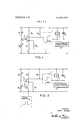
- FIGS. 1 and 2 are schematic wiring diagrams of first and second embodiments of the regulating arrangement in accordance with the invention
- FIG. 3 is a diagram graphically illustrating the operation of a known regulator which does not have any mistuning device for the input bridge;
- FIG. 4 is diagram graphically illustrating the operation of a regulating arrangement embodying the invention in such a manner that the difference between the cut-in and cutout points is zero.
- FIG. 1 schematically illustrates a regulating arrangement whose input is formed by a bridge connection.
- a first arm of the bridge is formed by an adjustable resistance R, and a negative temperature-dependent resistance R,,.
- the base B of a transistor amplifier T is connected to the junction point of resistances R, and R
- the second bridge arm is formed by a fixed resistance R, which is connected in series with a parallel combination of fixed resistances R, and R an interruptor f being connected in series with resistance R,.
- Resistance R is a very low ohmic resistance as compared with resistance R
- the only function of resistance R is to act as a protective resistance in order to limit the control voltage U,,,, in case of blockage.
- the emitter E of the transistor amplifier T is connected to the common junction point of resistances R R and R
- the diagonal voltage of the bridge forms the control voltage of the bridge transistor amplifier.
- Collector C of transistor amplifier T is in series with a collector resistance R, which forms, at the same time, the input resistance for the switching and threshold value amplifier or switch 1.
- the switch f is operable to mistune the bridge with a perfectly constant frequency.
- the control voltate U on the transistor amplifier T, between base B and emitter E is thus also varied. With a sufficiently high control volate U on transistor T, transistor T, becomes conductive so that a voltage drop appears across resistance R, by virtue of the collector current of the transistor amplifier. In turn this voltage either operates switch 1 or does not operate switch I depending on the magnitude of the voltage drop.
- the output of electronic switch 1, in FIG. 1, is represented by a relay 2 having a charging condenser 3 connected in parallel therewith.
- the ratio of the resistance of relay 2 and charging condenser 3 is so selected that relay 2 will not drop when supplied with pulses uninterruptedly.
- the relay controls a pulse-actuated electric element 10 such as a pump.
- FIG. 2 schematically illustrates a regulator which has the same construction as that of FIG. 1.
- resistance R is
- FIG. 3 graphically demonstrates how a normal regulator, having no bridge mistuning device, works.
- the control voltage U for the transistor amplifier is plotted as a function of a negative temperature-dependent resistance. It can be seen from FIG. 3 that, for the threshold value of the switch, there is a difference between the input voltage U, and the output voltage U This is generally called the hysteresis and is equal to AU so that a connecting and disconnecting potential difference appears at the temperature At.
- the invention arrangement has the effect that the on point and off point for the regulator coincide without the use of complicated feedback and compensating parts.
- the point of connection of the regulator is identical with the disconnecting point of the regulator. This, in turn, has a result that only the connecting point is used for regulation, since the threshold value more or less returns to a starting position due to the rhythmic influence of the measuring element.
- a regulator for responding to a varying value comprising bridge means having four arms and a diagonal, amplifier means having an input circuit forming the diagonal of said bridge means, output means connected to said amplifier means to respond thereto, input means for exhibiting a variable electrical value corresponding to the value to which the regulator responds and in one of the arms, and circuit means forming a second of said arms for repetitively varying the balance of said bridge means at a rate greater than the variation of the value of said input means.
- said impedance includes two resistors, and said switch means repetitively switches one of said resistors into and out of parallel arrangement with the other.
- said impedance includes a resistor and network means for repetitively shunting said resistor.
- said output means includes a relay and means for maintaining a voltage across said relay in response to repetitive voltage applied across said relay.
- said output means includes a pulse-operated electric element, responsive to voltages applied thereto and integrating means for maintaining the voltage applied across said pulse-operated electric element.
Landscapes
- Physics & Mathematics (AREA)
- General Physics & Mathematics (AREA)
- Engineering & Computer Science (AREA)
- Automation & Control Theory (AREA)
- Electrotherapy Devices (AREA)
- Amplifiers (AREA)
Applications Claiming Priority (1)
| Application Number | Priority Date | Filing Date | Title |
|---|---|---|---|
| DE19681801158 DE1801158B2 (de) | 1968-10-04 | 1968-10-04 | Brueckenregler mit einem in der brueckendiagonalen angeordneten schaltverstaerker |
Publications (1)
| Publication Number | Publication Date |
|---|---|
| US3649854A true US3649854A (en) | 1972-03-14 |
Family
ID=5709623
Family Applications (1)
| Application Number | Title | Priority Date | Filing Date |
|---|---|---|---|
| US838736A Expired - Lifetime US3649854A (en) | 1968-10-04 | 1969-07-03 | Regulating arrangement preferably for regulating the temperature in heating systems |
Country Status (5)
| Country | Link |
|---|---|
| US (1) | US3649854A (fr) |
| CH (1) | CH506836A (fr) |
| DE (1) | DE1801158B2 (fr) |
| FR (1) | FR2019885A1 (fr) |
| SE (1) | SE345536B (fr) |
Families Citing this family (1)
| Publication number | Priority date | Publication date | Assignee | Title |
|---|---|---|---|---|
| DE2949467C2 (de) * | 1979-12-08 | 1983-11-03 | Philips Kommunikations Industrie AG, 8500 Nürnberg | Verfahren zur Messung von Widerständen, Widerstandsdifferenzen und zum Fehlerorten |
Citations (4)
| Publication number | Priority date | Publication date | Assignee | Title |
|---|---|---|---|---|
| US1927846A (en) * | 1931-01-23 | 1933-09-26 | Radio Patents Corp | Electric amplifier |
| US3149224A (en) * | 1961-11-24 | 1964-09-15 | Monsanto Co | Heater control circuit |
| US3281653A (en) * | 1962-06-29 | 1966-10-25 | Johnson Service Co | Electronic system affording reversible modulating control |
| US3504196A (en) * | 1967-06-16 | 1970-03-31 | Westinghouse Electric Corp | Amplifying apparatus operable to two stable output states |
-
1968
- 1968-10-04 DE DE19681801158 patent/DE1801158B2/de active Pending
-
1969
- 1969-05-20 CH CH762969A patent/CH506836A/de not_active IP Right Cessation
- 1969-07-03 US US838736A patent/US3649854A/en not_active Expired - Lifetime
- 1969-09-08 FR FR6930436A patent/FR2019885A1/fr not_active Withdrawn
- 1969-10-06 SE SE13719/69A patent/SE345536B/xx unknown
Patent Citations (4)
| Publication number | Priority date | Publication date | Assignee | Title |
|---|---|---|---|---|
| US1927846A (en) * | 1931-01-23 | 1933-09-26 | Radio Patents Corp | Electric amplifier |
| US3149224A (en) * | 1961-11-24 | 1964-09-15 | Monsanto Co | Heater control circuit |
| US3281653A (en) * | 1962-06-29 | 1966-10-25 | Johnson Service Co | Electronic system affording reversible modulating control |
| US3504196A (en) * | 1967-06-16 | 1970-03-31 | Westinghouse Electric Corp | Amplifying apparatus operable to two stable output states |
Also Published As
| Publication number | Publication date |
|---|---|
| DE1801158A1 (fr) | 1970-04-23 |
| SE345536B (fr) | 1972-05-29 |
| FR2019885A1 (fr) | 1970-07-10 |
| CH506836A (de) | 1971-04-30 |
| DE1801158B2 (de) | 1972-08-17 |
Similar Documents
| Publication | Publication Date | Title |
|---|---|---|
| US3946200A (en) | Proportional temperature controller | |
| US3616846A (en) | Control system for heating and/or cooling system | |
| US4546238A (en) | Circuit arrangement for temperature control of an electric heating element | |
| US3523182A (en) | Variable cycle rate and duty cycle temperature controls | |
| US2488580A (en) | Temperature control system | |
| US2907931A (en) | Control apparatus | |
| US5125112A (en) | Temperature compensated current source | |
| US3474258A (en) | Solid state relays | |
| EP0400819A2 (fr) | Amplificateur opérationnel à courant de polarisation bas et à haute vitesse de balayage | |
| US2423534A (en) | Control apparatus | |
| US3107285A (en) | Temperature control system | |
| JP2898527B2 (ja) | 温度補償電圧発生回路 | |
| US3594546A (en) | Air temperature control apparatus | |
| US3239723A (en) | Alternating current voltage sensor | |
| US3649854A (en) | Regulating arrangement preferably for regulating the temperature in heating systems | |
| US4081696A (en) | Current squaring circuit | |
| GB940086A (en) | Improvements in or relating to voltage monitoring devices | |
| US3639810A (en) | Power system monitoring relay | |
| US3708700A (en) | Amplifier circuit | |
| US3046469A (en) | Transistor regulated power supply | |
| US2645744A (en) | Dual limit control circuit | |
| US3566252A (en) | Method of and means for digital programming of regulated power supplies | |
| JPH05335852A (ja) | デジタル振幅調整装置 | |
| US3648074A (en) | On-off controller with solid-state differential circuit | |
| US3528022A (en) | Temperature compensating networks |