US3662420A - Machine for removing chicken waste - Google Patents
Machine for removing chicken waste Download PDFInfo
- Publication number
- US3662420A US3662420A US867601A US3662420DA US3662420A US 3662420 A US3662420 A US 3662420A US 867601 A US867601 A US 867601A US 3662420D A US3662420D A US 3662420DA US 3662420 A US3662420 A US 3662420A
- Authority
- US
- United States
- Prior art keywords
- conveyor
- prime mover
- aisle
- supported
- attachment
- Prior art date
- Legal status (The legal status is an assumption and is not a legal conclusion. Google has not performed a legal analysis and makes no representation as to the accuracy of the status listed.)
- Expired - Lifetime
Links
- 241000287828 Gallus gallus Species 0.000 title abstract description 44
- 239000002699 waste material Substances 0.000 title description 6
- 239000000463 material Substances 0.000 claims description 14
- 239000013590 bulk material Substances 0.000 claims description 2
- 230000002093 peripheral effect Effects 0.000 claims description 2
- 210000003608 fece Anatomy 0.000 abstract description 12
- 239000010871 livestock manure Substances 0.000 description 7
- 238000010276 construction Methods 0.000 description 3
- 238000007599 discharging Methods 0.000 description 2
- 230000004048 modification Effects 0.000 description 2
- 238000012986 modification Methods 0.000 description 2
- 238000006073 displacement reaction Methods 0.000 description 1
- 230000005923 long-lasting effect Effects 0.000 description 1
- 238000004519 manufacturing process Methods 0.000 description 1
- 244000144977 poultry Species 0.000 description 1
- 238000007790 scraping Methods 0.000 description 1
- XLYOFNOQVPJJNP-UHFFFAOYSA-N water Substances O XLYOFNOQVPJJNP-UHFFFAOYSA-N 0.000 description 1
Images



Classifications
-
- A—HUMAN NECESSITIES
- A01—AGRICULTURE; FORESTRY; ANIMAL HUSBANDRY; HUNTING; TRAPPING; FISHING
- A01K—ANIMAL HUSBANDRY; AVICULTURE; APICULTURE; PISCICULTURE; FISHING; REARING OR BREEDING ANIMALS, NOT OTHERWISE PROVIDED FOR; NEW BREEDS OF ANIMALS
- A01K31/00—Housing birds
- A01K31/04—Dropping-boards; Devices for removing excrement
Definitions
- ABSTRACT An attachment for a prime mover to be moved along a path paralleling a row of elevated chicken cages beneath which chicken droppings fall to the ground.
- the attachment includes an elongated driven auger conveyor open along one side and supported from the prime mover in horizontal transversely extending position with its open side facing forwardly in the intended direction of movement of the prime mover.
- One end of the conveyor projects outwardly from the corresponding side of the prime mover for passing beneath the cages and includes a forwardly and downwardly inclined chute for engagement with the ground beneath the cages and directing chicken droppings upwardly toward the conveyor as the prime mover is advanced forwardly.
- the machine of the instant invention is designed to clean chicken manure out of poultry houses including concrete aisles between rows of elevated cages.
- the houses may be constructed in different widths, but the same general spacing exists between rows of elevated cages.
- some chicken farms utilize chicken houses having two rows of cages in each house and other farms utilize houses having four rows of cages.
- the houses have posts supporting the roof of each house and the cages are hung from the rafters and roof framework. However, the houses are open along opposite sides except for the posts supporting the outer edges of the roofs thereof and there are no obstructions between rows of roof supporting posts beneath the elevated cages.
- the attachment of the instant invention is designed to be supported and driven from any suitable prime mover having a front mounted power take-off such as a 424 Gravely tractor.
- the attachment is therefore mounted on the front of the tractor although it is possible that the attachment could be rear mounted on the associated tractor if the latter is provided with a rear mounted power take-off.
- Another object of this invention is to provide an attachment for picking up and laterally discharging chicken manure from beneath rows of suspended chicken cages and which may be readily mounted on and powered by a relatively inexpensive prime mover such as a garden type tractor.
- a still further object of this invention is to provide a machine for removing chicken waste in accordance with the preceding objects and which may be readily operated by a single person.
- a final object of this invention to be specifically enumerated herein is to provide a machine for removing chicken waste which will conform to conventional forms of manufacture, be of simple construction and easy to use so as to provide a device that will be economically feasible, long lasting and relatively trouble-free in operation.
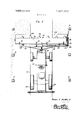
- FIG. 1 is an elevational view of a conventional form of chicken house in which two pairs of rows of suspended chicken cages are supported from the upper structures of the chicken house and concrete aisles are provided between the rows of each pair of rows of cages, a pair of the chicken waste removing machines of the instant invention being illustrated in operative position along the aisles for collecting and laterally discharging chicken manure to the outside of the longitudinal sides of the chicken house;
- FIG. 2 is an enlarged fragmentary horizontal sectional view illustrating the manner in which the machine of the instant invention is operative to move along each aisle, collect chicken manure from the opposite sides of the aisle and laterally discharge the collected chicken manure outwardly of one side of the associated chicken house;
- FIG. 3 is an enlarged side elevational view of the assemblage illustrated in FIG. 2 and with the posts of the chicken house removed;
- FIG. 7 is a fragmentary perspective view illustrating the mount by which the attachment of the instant invention is mounted upon the forward end of a garden tractor.
- the numeral 10 generally designates a conventional form of chicken house which includes a roof structure 12 supported by inner longitudinal rows of posts 14 and outer longitudinal rows of posts 16.
- the chicken house 10 further includes longitudinal rows of chicken cages 18 which are suspended from the roof structure 12 and the posts 14 and 16.
- One pair of longitudinal rows of cages 18 are supported from the adjacent sides of each pair of rows of adjacent posts 14 and 16 and it may be seen from FIG. 1 of the drawings that the area between each pair of posts 14 and 16 and beneath the associated cages 18 is open.
- FIG. 2 of the drawings it may be seen that the chicken house 10 is devoid of side walls and that the sides of the chicken house 10 beneath the cages 18 are open except for the posts 16.
- the attachment of the instant invention includes a mounting structure referred to in general by the reference numeral 26 consisting of a pair of forwardly and downwardly inclined arms 28 secured at their upper rear ends to the opposite sides of the frame of the tractor 22 in any convenient manner such as by fasteners 30.
- the forward sides of the arms 28 are provided with forwardly opening notches 32 adjacent the lower ends of the arms 28 and a generally U-shaped mount referred to in general by the reference numeral 34 is provided and includes a pair of rearwardly directed legs 36 interconnected at their forward ends by means of a forward transverse bight portion 38.
- the rear ends of the legs 36 include oppositely outwardly directed stub shafts 40 which are slidingly and rotatably received in the rear closed ends of the notches 32 and a pair of pivoted latches 42 are provided to releasably retain the stub shafts or pins 40 within the inner ends of the notches 32.
- the central portion of the bight portion 38 is enlarged as at 44 and is provided with a central aperture 46 and a plurality of mounting apertures 48.
- a right angle gear drive assembly referred to in general by the reference numeral 50 is provided and includes a mounting sleeve portion 52 whose flanged end 54 is secured to the enlarged portion 44 of the bight portion 38 by means of suitable fasteners 56.
- An input shaft 58 for the right angled drive assembly 50 is journaled through the mounting sleeve portion 52 and projects through the central bore or aperture 46 in the bight portion 38.
- a connecting shaft 60 connects the power take-off shaft 24 which is journaled through the front axle beam 62 of the tractor 22 to the input shaft 58 of the drive assembly 50 and is connected to the power take-off shaft 24 by means of a universal joint 64 and to the input shaft 58 by means of a universal joint 66.
- the attachment includes a main transverse beam 68 from which an anger conveyor assembly referred to in general by the reference numeral 70 is supported by means of gussets 72 secured between the beam 68 and the auger screw conveyor assembly 70.
- the gussets 72 are connected between the beam 68 and the semi-cylindrical housing 74 of the assembly 70.
- the housing 74 is open along one side and the open side of the housing 74 faces forwardly in relation to the tractor 22.
- the housing 74 includes a pair of end plates 76 at its opposite ends and an auger screw 78 is joumaled from a pair of pillow blocks 80 supported from the end plates 76.
- the right hand end of the auger conveyor assembly 70 in'- cludes an extension 76 of its end plate 76 which projects forwardly from the corresponding end of the assembly 70 and the extension 76 has a forwardly projecting guide plate 94 supported therefrom by means of suitable fasteners 96 carried by the extension 76 and received through horizontal slots 98 formed in the guide plate 94.
- the extension 76 is inclined forwardly and outwardly from the right hand end of the assembly 70 and that portion of the guide plate 94 which overlaps the extension 76 is also angled forwardly and outwardly, whereas the free end of the guide plate 94 generally parallels the longitudinal centerline of the tractor 22.
- the guide plate 94 may be adjusted slightly so as to be shifted slightly laterally of the centerline of the tractor 22 and thereby adjust the right hand reach of the auger conveyor assembly 70.
- the central portion of the auger conveyor assembly 70 which rides over the concrete aisle 22 is provided with caster support wheels 100 including shank portions 102 received upwardly through a pair of apertured mounting lugs 104 secured to the rear surface of the housing 74.
- a plurality of washers 106 are utilized on the mounting shank 102 of each caster wheel 100 to adjust the minimum clearance between the lower forward edge of the housing 74 and the concrete aisle 20.
- the upper ends of the mounting shanks 102 are secured through the uppermost apertured mounting lugs 104 in any convenient manner.
- the mounting lugs 104 are not only supported from the rear surface of the housing 74 but also from a pair of the gussets 72.
- the rear end of the tractor 22 is provided with a pair of mounts 124 from which a pivot shaft 126 is oscillatably supported.
- the opposite ends of the pivot shaft 126 are disposed slightly outwardly of the outer sides of the rear wheels 128 of the tractor 22 and a pair of lever arms 130 are mounted on the outer ends of the pivot shaft 126 and depend downwardly therefrom.
- the lower ends of the lever arms 130 have vertical rollers 132 journaled therefrom and a control lever 134 is journaled from the tractor 22 as at 136 and has a handgrip 138 at its upper end and a lower end 140 disposed below its pivot axis.
- a control rod 142 is connected between the right hand lever arm 130 and the lower end of the lever 134 and a rod 144 is connected between the lower end of the lever 134 and a depending lug 146 carried by and depending from the right hand leg 30 of the mount 34. Accordingly, the auger conveyor assembly 70 as well as the rollers 132 may be raised by pulling rearwardon the handgrip 138 at the top of the lever 134. Any suitable means (not shown) may be utilized to secure the upper end of the lever 134 in a rearwardly displaced position with the assembly 70 and the rollers 132 raised from the positions thereof illustrated in FIG. 3 of the drawings.
- the upper end of the lever 134 may be pulled rearwardly so as to elevate the assembly 70 and the rollers 132 after which the tractor is turned and headed down through the left hand side of the chicken house 10 illustrated in FIG. 1 in the direction of the background of FIG. 1.
- the upper end of the lever 134 is allowed to move forwardly whereupon the assembly 70 will be lowered with its caster wheels engaging the upper surface of the left hand aisle 20 and the forward edges of the ramp plates 108 scraping the ground on opposite sides of the left hand aisle 20.
- the rollers 132 are again lowered and closely embrace the opposite side edges of the aisle 20.
- an attachment supported from said prime mover for movement therewith, said attachment being adapted to engage, pick up and convey said material transversely across said aisle for discharge outwardly of the other side of said aisle
- said attachment including an elongated horizontal conveyor including one open side supported from said prime mover with the conveyor extending transversely of the prime mover with its open side facing in said one direction and one end portion of the conveyor projecting outwardly of the side of said prime mover adjacent said path and over the latter, said one end portion of said conveyor including a chute projecting outwardly of said open side of said conveyor in said one direction and supported from the lower marginal portion of said one end portion of said conveyor for adjustable swinging at its free extended end through a vertical plane, said conveyor including means operative to engage material moving along said chute toward said conveyor and convey the engaged material along said conveyor toward the other end thereof, said prime mover including driven ground
- said conveyor comprises an auger screw conveyor including a generally semicylindn'cal housing from which an auger screw member is rotatably journaled.
- said conveyor includes vertically adjustable ground engaging wheel means spaced inwardly from the opposite end portions of said conveyor and adjustable to limit downward movement of said conveyor assembly relative to a surface such as said aisle with which said ground engageable wheels are engageable.
- said conveyor comprises an auger screw conveyor including a generally semicylindrical housing from which an auger screw member is rotatably joumaled, said prime mover including a power takeoff drivingly connected to said auger screw.
Landscapes
- Life Sciences & Earth Sciences (AREA)
- Environmental Sciences (AREA)
- Birds (AREA)
- Zoology (AREA)
- Animal Husbandry (AREA)
- Biodiversity & Conservation Biology (AREA)
- Agricultural Machines (AREA)
Abstract
An attachment for a prime mover to be moved along a path paralleling a row of elevated chicken cages beneath which chicken droppings fall to the ground. The attachment includes an elongated driven auger conveyor open along one side and supported from the prime mover in horizontal transversely extending position with its open side facing forwardly in the intended direction of movement of the prime mover. One end of the conveyor projects outwardly from the corresponding side of the prime mover for passing beneath the cages and includes a forwardly and downwardly inclined chute for engagement with the ground beneath the cages and directing chicken droppings upwardly toward the conveyor as the prime mover is advanced forwardly.
Description
United States Patent Jordan, Jr.
[ 1 May 16,1972
[54] MACHINE FOR REMOVING CHICKEN WASTE [72] Inventor: Tommy V. Jordan, Jr., Route 3, PO. Box
[52] US. Cl ..15/93 B, 198/126, 198/213,
119/22, 119/28 [51] Int. Cl. ..A0lk 31/04 [58] Field of Search ..198/7, DIG. 18, 213, 123, 126,
2,907,124 10/1959 Graham .....198/7 X 3,011,273 12/1961 Stumpf.... .....198/7 X 3,143,977 8/1964 Deller ....104/120 X 3,234,891 2/1966 Hampton et a1. ....104/247 X 3,503,450 3/1970 Day ..37/43 R X 3,017,008 1/1962 Olson ..198/7 Primary ExaminerPhilip Arnold AttorneyClarence A. OBrien and Harvey B. Jacobson [57] ABSTRACT An attachment for a prime mover to be moved along a path paralleling a row of elevated chicken cages beneath which chicken droppings fall to the ground. The attachment includes an elongated driven auger conveyor open along one side and supported from the prime mover in horizontal transversely extending position with its open side facing forwardly in the intended direction of movement of the prime mover. One end of the conveyor projects outwardly from the corresponding side of the prime mover for passing beneath the cages and includes a forwardly and downwardly inclined chute for engagement with the ground beneath the cages and directing chicken droppings upwardly toward the conveyor as the prime mover is advanced forwardly.
7 Claims, 7 Drawing Figures PATENTEWY 16 1972 SPEEI 1 OF 4 Tammy V. Jordan, Jr.
/. I/l.. TOP.
9 I. IJY
W a Attorney;
I .3 on
PATENTED um 15 I972 SHEET 2 OF 4 Tommy V. Jordan, Jr.
IIY Ema PATENTED MAY 1 6 I572 SHEET 3 OF 4 Tommy V. Jordan, Jr.
w Mm
mflzlweyfim 8 m& QQ Q .wm
H vm vm k wk 0mm:
- a x 3 o PATENTEDMAY 16 m2 sum u UF 4 Tommy 1 Jordan, Jr.
in a,
um V m:
L vo\ u: mm m \h mm .wsv W mm vm 9w r wm mm X mm l n I V% 0 0 O I m wn mm vm m an ww J m: E E u 9n n The machine of the instant invention is designed to clean chicken manure out of poultry houses including concrete aisles between rows of elevated cages. The houses may be constructed in different widths, but the same general spacing exists between rows of elevated cages. Further, some chicken farms utilize chicken houses having two rows of cages in each house and other farms utilize houses having four rows of cages. The houses have posts supporting the roof of each house and the cages are hung from the rafters and roof framework. However, the houses are open along opposite sides except for the posts supporting the outer edges of the roofs thereof and there are no obstructions between rows of roof supporting posts beneath the elevated cages.
The attachment of the instant invention is designed to be supported and driven from any suitable prime mover having a front mounted power take-off such as a 424 Gravely tractor. The attachment is therefore mounted on the front of the tractor although it is possible that the attachment could be rear mounted on the associated tractor if the latter is provided with a rear mounted power take-off.
The main object of this invention is to provide an attachment for a prime mover which may be utilized to collect, convey and laterally discharge chicken manure as the prime mover to which the attachment is secured moves along an aisle between adjacent rows of suspended chicken cages.
Another object of this invention, in accordance with the immediately preceding object, is to provide an attachment for picking up and laterally discharging chicken manure from beneath rows of suspended chicken cages and which may be readily mounted on and powered by a relatively inexpensive prime mover such as a garden type tractor.
A still further object of this invention is to provide a machine for removing chicken waste in accordance with the preceding objects and which may be readily operated by a single person.
Another important object of this invention is to provide a machine for removing chicken waste which may be readily driven from one chicken house to another with actuation of only one control being required to condition the attachment for transport during its movement from one chicken house to another.
A final object of this invention to be specifically enumerated herein is to provide a machine for removing chicken waste which will conform to conventional forms of manufacture, be of simple construction and easy to use so as to provide a device that will be economically feasible, long lasting and relatively trouble-free in operation.
These together with other objects and advantages which will become subsequently apparent reside in the details of construction and operation as more fully hereinafter described and claimed, reference being had to the accompanying drawings forming a part hereof, wherein like numerals refer to like parts throughout, and in which:
FIG. 1 is an elevational view of a conventional form of chicken house in which two pairs of rows of suspended chicken cages are supported from the upper structures of the chicken house and concrete aisles are provided between the rows of each pair of rows of cages, a pair of the chicken waste removing machines of the instant invention being illustrated in operative position along the aisles for collecting and laterally discharging chicken manure to the outside of the longitudinal sides of the chicken house;
FIG. 2 is an enlarged fragmentary horizontal sectional view illustrating the manner in which the machine of the instant invention is operative to move along each aisle, collect chicken manure from the opposite sides of the aisle and laterally discharge the collected chicken manure outwardly of one side of the associated chicken house;
FIG. 3 is an enlarged side elevational view of the assemblage illustrated in FIG. 2 and with the posts of the chicken house removed;
FIG. 4 is a transverse vertical sectional view taken substantially upon the plane indicated by the section line 4--4 of FIG. 3-
FIG. 5 is an enlarged fragmentary longitudinal vertical sectional view taken substantially upon a plane passing along the longitudinal centerline of the front end of the machine;
FIG. 6 is a fragmentary transverse vertical sectional view taken substantially upon the plane indicated by the section line 66 of FIG. 5; and
FIG. 7 is a fragmentary perspective view illustrating the mount by which the attachment of the instant invention is mounted upon the forward end of a garden tractor.
Referring now more specifically to the drawings the numeral 10 generally designates a conventional form of chicken house which includes a roof structure 12 supported by inner longitudinal rows of posts 14 and outer longitudinal rows of posts 16. The chicken house 10 further includes longitudinal rows of chicken cages 18 which are suspended from the roof structure 12 and the posts 14 and 16. One pair of longitudinal rows of cages 18 are supported from the adjacent sides of each pair of rows of adjacent posts 14 and 16 and it may be seen from FIG. 1 of the drawings that the area between each pair of posts 14 and 16 and beneath the associated cages 18 is open. Further, from FIG. 2 of the drawings it may be seen that the chicken house 10 is devoid of side walls and that the sides of the chicken house 10 beneath the cages 18 are open except for the posts 16.
The chicken house 10 is provided with raised concrete aisles 20 disposed between adjacent rows of cages l8 and the aisles 20 are of a width to receive a conventional form of garden tractor such as that generally designated by the reference numeral 22 thereon. The garden tractor 22 may be of any suitable conventional tractor such as a 424 Gravely tractor which includes a front axle mounted power take-off shaft 24.
The attachment of the instant invention includes a mounting structure referred to in general by the reference numeral 26 consisting of a pair of forwardly and downwardly inclined arms 28 secured at their upper rear ends to the opposite sides of the frame of the tractor 22 in any convenient manner such as by fasteners 30. The forward sides of the arms 28 are provided with forwardly opening notches 32 adjacent the lower ends of the arms 28 and a generally U-shaped mount referred to in general by the reference numeral 34 is provided and includes a pair of rearwardly directed legs 36 interconnected at their forward ends by means of a forward transverse bight portion 38. The rear ends of the legs 36 include oppositely outwardly directed stub shafts 40 which are slidingly and rotatably received in the rear closed ends of the notches 32 and a pair of pivoted latches 42 are provided to releasably retain the stub shafts or pins 40 within the inner ends of the notches 32. The central portion of the bight portion 38 is enlarged as at 44 and is provided with a central aperture 46 and a plurality of mounting apertures 48. A right angle gear drive assembly referred to in general by the reference numeral 50 is provided and includes a mounting sleeve portion 52 whose flanged end 54 is secured to the enlarged portion 44 of the bight portion 38 by means of suitable fasteners 56. An input shaft 58 for the right angled drive assembly 50 is journaled through the mounting sleeve portion 52 and projects through the central bore or aperture 46 in the bight portion 38. A connecting shaft 60 connects the power take-off shaft 24 which is journaled through the front axle beam 62 of the tractor 22 to the input shaft 58 of the drive assembly 50 and is connected to the power take-off shaft 24 by means of a universal joint 64 and to the input shaft 58 by means of a universal joint 66.
The attachment includes a main transverse beam 68 from which an anger conveyor assembly referred to in general by the reference numeral 70 is supported by means of gussets 72 secured between the beam 68 and the auger screw conveyor assembly 70. The gussets 72 are connected between the beam 68 and the semi-cylindrical housing 74 of the assembly 70. The housing 74 is open along one side and the open side of the housing 74 faces forwardly in relation to the tractor 22. The housing 74 includes a pair of end plates 76 at its opposite ends and an auger screw 78 is joumaled from a pair of pillow blocks 80 supported from the end plates 76. The drive assembly 50 includes an output sleeve portion 82 which projects outwardly along the left hand side of the auger conveyor assembly 70 and has an output shaft 84 joumaled therethrough which is driven from the input shaft 58. The outer end of the output shaft 84 has a sprocket wheel 86 mounted thereon aligned with a sprocket wheel 88 mounted on the adjacent end of the auger screw 78 which projects through the right hand end plate 76. An endless flexible chain 90 is entrained about the sprocket wheels 86 and 88 and accordingly, the auger screw 78 is driven by the power take-off shaft 24.
The right hand end of the auger conveyor assembly 70 in'- cludes an extension 76 of its end plate 76 which projects forwardly from the corresponding end of the assembly 70 and the extension 76 has a forwardly projecting guide plate 94 supported therefrom by means of suitable fasteners 96 carried by the extension 76 and received through horizontal slots 98 formed in the guide plate 94. The extension 76 is inclined forwardly and outwardly from the right hand end of the assembly 70 and that portion of the guide plate 94 which overlaps the extension 76 is also angled forwardly and outwardly, whereas the free end of the guide plate 94 generally parallels the longitudinal centerline of the tractor 22. The guide plate 94 may be adjusted slightly so as to be shifted slightly laterally of the centerline of the tractor 22 and thereby adjust the right hand reach of the auger conveyor assembly 70.
The central portion of the auger conveyor assembly 70 which rides over the concrete aisle 22 is provided with caster support wheels 100 including shank portions 102 received upwardly through a pair of apertured mounting lugs 104 secured to the rear surface of the housing 74. A plurality of washers 106 are utilized on the mounting shank 102 of each caster wheel 100 to adjust the minimum clearance between the lower forward edge of the housing 74 and the concrete aisle 20. Of course, the upper ends of the mounting shanks 102 are secured through the uppermost apertured mounting lugs 104 in any convenient manner. In addition, the mounting lugs 104 are not only supported from the rear surface of the housing 74 but also from a pair of the gussets 72.
The forward lower edge portions of the housing 74 disposed at opposite ends of the assembly 70 are provided with pivoted rump plates 108 which are inclined forwardly and downwardly from the lower forward edge portions of the housing 74 at opposite ends of the housing 74 and have their rear upper edge portions pivotally secured to the housing 74 by means of piano-type hinges 110. In addition, each of the ramp plates 108 includes a rearwardly projecting adjustment plate 112 which projects rearwardly from the corresponding hinge assembly 110 and has a threaded sleeve 114 oscillatably supported therefrom through which the lower end of a corresponding jack screw 116 is threadedly engaged. Each of the jack screws 116 includes a handle 118 at its upper end and the mid-portion of each jack screw 116 is joumaled through a mount 120 supported from the forward side of the transverse mounting beam 68 against axial displacement relative to the journal 120. Thus, rotation of the handle or crank 118 will cause the plates 112 and thus the plates 108 to be angularly displaced relative to the housing 74. In this manner, the height or cut" of the forward lower edges of the ramp plates 108 may be adjusted.
The rear end of the tractor 22 is provided with a pair of mounts 124 from which a pivot shaft 126 is oscillatably supported. The opposite ends of the pivot shaft 126 are disposed slightly outwardly of the outer sides of the rear wheels 128 of the tractor 22 and a pair of lever arms 130 are mounted on the outer ends of the pivot shaft 126 and depend downwardly therefrom. The lower ends of the lever arms 130 have vertical rollers 132 journaled therefrom and a control lever 134 is journaled from the tractor 22 as at 136 and has a handgrip 138 at its upper end and a lower end 140 disposed below its pivot axis. A control rod 142 is connected between the right hand lever arm 130 and the lower end of the lever 134 and a rod 144 is connected between the lower end of the lever 134 and a depending lug 146 carried by and depending from the right hand leg 30 of the mount 34. Accordingly, the auger conveyor assembly 70 as well as the rollers 132 may be raised by pulling rearwardon the handgrip 138 at the top of the lever 134. Any suitable means (not shown) may be utilized to secure the upper end of the lever 134 in a rearwardly displaced position with the assembly 70 and the rollers 132 raised from the positions thereof illustrated in FIG. 3 of the drawings.
in operation, the tractor 22 may have the attachment of the instant invention mounted thereon in a manner believed to be clear from the foregoing description. Then, the tractor may be advanced through the right hand side of the chicken house 10 illustrated in FIG. 1 toward the foreground with the ramp plates 108 downwardly adjusted so as to scrape the ground along each side of the right hand aisle 20. The chicken manure scraped from the ground and rearwardly and upwardly along the ramp plates 108 is engaged by the auger screw 78 and carried to the left hand side of the vehicle at the right hand side of the chicken house 10 and discharged outwardly between the outer posts 16 on the right hand side of the chicken house 10. Then, as the tractor 22 exits from the chicken house 10 in the foreground of FIG. 1, the upper end of the lever 134 may be pulled rearwardly so as to elevate the assembly 70 and the rollers 132 after which the tractor is turned and headed down through the left hand side of the chicken house 10 illustrated in FIG. 1 in the direction of the background of FIG. 1. As the tractor enters the chicken house 10, the upper end of the lever 134 is allowed to move forwardly whereupon the assembly 70 will be lowered with its caster wheels engaging the upper surface of the left hand aisle 20 and the forward edges of the ramp plates 108 scraping the ground on opposite sides of the left hand aisle 20. Also, the rollers 132 are again lowered and closely embrace the opposite side edges of the aisle 20. Inasmuch as the chicken droppings are conveyed across the concrete aisle and the upper surface of the aisle 20 is thus slippery, even when the rear tires 128 of the tractor 122 are weighted and filled with water, traction of the tractor 122 is limited. Accordingly, there is a tendency for the rear wheels of the tractor 22 to spin and thus for the rear end of the tractor 22 to slide to either the right or the left. Of course, with the rollers 132 in their lowered positions, the rear end of the tractor 22 is held in a position centered on the aisle 20 and thus prevented from sliding off either side of the aisle 20.
The foregoing is considered as illustrative only of the principles of the invention. Further, since numerous modifications and changes will readily occur to those skilled in the art, it is not desired to limit the invention to the exact construction and operation shown and described, and accordingly all suitable modifications and equivalents may be resorted to, falling within the scope of the invention.
What is claimed as new is as follows:
1. in combination with a prime mover adapted to be moved in one direction along an aisle elevated slightly above one side of a path along which said aisle extends and upon which loose bulk material is disposed, an attachment supported from said prime mover for movement therewith, said attachment being adapted to engage, pick up and convey said material transversely across said aisle for discharge outwardly of the other side of said aisle, said attachment including an elongated horizontal conveyor including one open side supported from said prime mover with the conveyor extending transversely of the prime mover with its open side facing in said one direction and one end portion of the conveyor projecting outwardly of the side of said prime mover adjacent said path and over the latter, said one end portion of said conveyor including a chute projecting outwardly of said open side of said conveyor in said one direction and supported from the lower marginal portion of said one end portion of said conveyor for adjustable swinging at its free extended end through a vertical plane, said conveyor including means operative to engage material moving along said chute toward said conveyor and convey the engaged material along said conveyor toward the other end thereof, said prime mover including driven ground engaging wheels at one end thereof and steerable ground engaging wheels at the other end thereof, said one end of said prime mover including depending follower portions retractable upwardly from positions projecting below the lower peripheral portions of said driven wheels and engageable with the opposite side edges of said aisle, when lowered, to prevent lateral skidding of said one end of said prime mover relative to said aisle.
2. The combination of claim 1 wherein the other end portion also projects outwardly of the corresponding side of said prime mover and includes a second chute projecting outwardly of the open side of said conveyor and supported from the lower marginal portion of said other end portion of said conveyor for adjustable swinging at its free extended end through a vertical plane.
3. The combination of claim 2 wherein said means operative to engage material moving along the first mentioned chute is also operative to engage material moving along the second chute toward said conveyor and convey the last mentioned material as well as the first mentioned material endwise outwardly of said other end portion of said conveyor.
4. The combination of claim 1 wherein said conveyor comprises an auger screw conveyor including a generally semicylindn'cal housing from which an auger screw member is rotatably journaled.
5. The combination of claim 1 wherein said attachment is supported from said prime mover for swinging movement relative thereto about a horizontal axis extending transversely of said prime mover and spaced outwardly from the side of said conveyor remote from the open side thereof.
6. The combination of claim 5 wherein said conveyor includes vertically adjustable ground engaging wheel means spaced inwardly from the opposite end portions of said conveyor and adjustable to limit downward movement of said conveyor assembly relative to a surface such as said aisle with which said ground engageable wheels are engageable.
7. The combination of claim 1 wherein said conveyor comprises an auger screw conveyor including a generally semicylindrical housing from which an auger screw member is rotatably joumaled, said prime mover including a power takeoff drivingly connected to said auger screw.
Claims (7)
1. In combination with a prime mover adapted to be moved in one direction along an aisle elevated slightly above one side of a path along which said aisle extends and upon which loose bulk material is disposed, an attachment supported from said prime mover for movement therewith, said attachment being adapted to engage, pick up and convey said material transversely across said aisle for discharge outwardly of the other side of said aisle, said attachment including an elongated horizontal conveyor including one open side supported from said prime mover with the conveyor extending transversely of the prime mover with its open side facing in said one direction and one end portion of the conveyor projecting outwardly of the side of said prime mover adjacent said path and over the latter, said one end portion of said conveyor including a chute projecting outwardly of said open side of said conveyor in said one direction and supported from the lower marginal portion of said one end portion of said conveyor for adjustable swinging at its free extended end through a vertical plane, said conveyor including means operative to engage material moving along said chute toward said conveyor and convey the engaged material along said conveyor toward the other end thereof, said prime mover including driven ground engaging wheels at one end thereof and steerable ground engaging wheels at the other end thereof, said one end of said prime mover including depending follower portions retractable upwardly from positions projecting below the lower peripheral portions of said driven wheels and engageable with the opposite side edges of said aisle, when lowered, to prevent lateral skidding of said one end of said prime mover relative to said aisle.
2. The combination of claim 1 wherein the other end portion also projects outwardly of the corresponding side of said prime mover and includes a second chute projecting outwardly of the open side of said conveyor and supported from the lower marginal portion of said other end portion of said conveyor for adjustable swinging at its free extended end through a vertical plane.
3. The combination of claim 2 wherein said means operative to engage material moving along the first mentioned chute is also operative to engage material moving along the second chute toward said conveyor and convey the last mentioned material as well as the first mentioned material endwise outwardly of said other end portion of said conveyor.
4. The combination of claim 1 wherein said conveyor comprises an auger screw conveyor including a generally semi-cylindricAl housing from which an auger screw member is rotatably journaled.
5. The combination of claim 1 wherein said attachment is supported from said prime mover for swinging movement relative thereto about a horizontal axis extending transversely of said prime mover and spaced outwardly from the side of said conveyor remote from the open side thereof.
6. The combination of claim 5 wherein said conveyor includes vertically adjustable ground engaging wheel means spaced inwardly from the opposite end portions of said conveyor and adjustable to limit downward movement of said conveyor assembly relative to a surface such as said aisle with which said ground engageable wheels are engageable.
7. The combination of claim 1 wherein said conveyor comprises an auger screw conveyor including a generally semi-cylindrical housing from which an auger screw member is rotatably journaled, said prime mover including a power take-off drivingly connected to said auger screw.
Applications Claiming Priority (1)
| Application Number | Priority Date | Filing Date | Title |
|---|---|---|---|
| US86760169A | 1969-10-20 | 1969-10-20 |
Publications (1)
| Publication Number | Publication Date |
|---|---|
| US3662420A true US3662420A (en) | 1972-05-16 |
Family
ID=25350113
Family Applications (1)
| Application Number | Title | Priority Date | Filing Date |
|---|---|---|---|
| US867601A Expired - Lifetime US3662420A (en) | 1969-10-20 | 1969-10-20 | Machine for removing chicken waste |
Country Status (1)
| Country | Link |
|---|---|
| US (1) | US3662420A (en) |
Cited By (13)
| Publication number | Priority date | Publication date | Assignee | Title |
|---|---|---|---|---|
| US3721214A (en) * | 1971-07-21 | 1973-03-20 | W Staples | Removal and disposal of manure from suspended cage chicken houses |
| US3845517A (en) * | 1973-01-10 | 1974-11-05 | J Harris | Scraper attachment |
| US4321887A (en) * | 1981-01-19 | 1982-03-30 | Favorite Manufacturing, Inc. | High-density poultry cage system and manure handling method |
| DE4017080A1 (en) * | 1990-05-26 | 1991-11-28 | Gerhard Plessing | Loosening litter in stalls - involves automatic device with grubber pulled by winch cables |
| US5749114A (en) * | 1996-07-12 | 1998-05-12 | Miller, Jr.; A. Glenn | Poultry house cleaner apparatus |
| US6000647A (en) * | 1998-07-21 | 1999-12-14 | Hardy; Larry E. | Implement for cleaning chicken houses |
| US6467432B1 (en) | 2001-10-03 | 2002-10-22 | Lewis Bros. Mfg., L.L.C. | Poultry house litter implement |
| US6820358B1 (en) | 2002-01-14 | 2004-11-23 | Louie Huelsewiesche | Compact vehicle for composting manure storage under high-rise avian houses |
| US20060272927A1 (en) * | 2005-05-19 | 2006-12-07 | Baber Timothy E | Intake feeding for agricultural vacuum conveyors |
| US7574766B1 (en) | 2005-08-11 | 2009-08-18 | Kevin Davis | Poultry house floor and wall cleaner |
| US20130092095A1 (en) * | 2011-10-12 | 2013-04-18 | Jason Morris | Windrower Machine |
| US20190133072A1 (en) * | 2017-11-08 | 2019-05-09 | Daniel L. Hintsala | Poultry Barn Debris Removal System |
| US10645902B1 (en) | 2016-07-18 | 2020-05-12 | Messer Repair and Fabricating, LLC. | Stall plow |
Citations (12)
| Publication number | Priority date | Publication date | Assignee | Title |
|---|---|---|---|---|
| US1394651A (en) * | 1919-12-30 | 1921-10-25 | Tompkins Gilbert | Agricultural implement |
| US1910120A (en) * | 1930-08-13 | 1933-05-23 | Robert T Mowbray | Soil shaping side attachment for road grading apparatus |
| US2417111A (en) * | 1945-03-13 | 1947-03-11 | Jeoffroy Roy | Portable grain elevator |
| US2713479A (en) * | 1951-02-28 | 1955-07-19 | Joy Mfg Co | Continuous mining apparatus with floor clean up devices |
| US2907124A (en) * | 1957-07-22 | 1959-10-06 | Edward S Graham | Sludge bed cleaner |
| US3011273A (en) * | 1960-02-12 | 1961-12-05 | Stumpf Raymond | Snow remover |
| US3017008A (en) * | 1954-05-10 | 1962-01-16 | Edward M Olson | Barn cleaning apparatus |
| US3143977A (en) * | 1960-03-23 | 1964-08-11 | Alweg Forschung Gmbh | Bogies for monorail vehicles |
| US3160141A (en) * | 1963-02-15 | 1964-12-08 | Alpheus S Crutchfield | Equipment for cleaning poultry houses |
| US3234891A (en) * | 1960-08-26 | 1966-02-15 | Pneuways Dev Company Private L | Highway vehicle with rail guide wheel means |
| US3264667A (en) * | 1964-06-08 | 1966-08-09 | Hyde Park Farm Supply Ltd | Pit cleaner for poultry cages |
| US3503450A (en) * | 1967-07-17 | 1970-03-31 | Chester B Day | Spiral conveyor backfill attachment for bulldozers |
-
1969
- 1969-10-20 US US867601A patent/US3662420A/en not_active Expired - Lifetime
Patent Citations (12)
| Publication number | Priority date | Publication date | Assignee | Title |
|---|---|---|---|---|
| US1394651A (en) * | 1919-12-30 | 1921-10-25 | Tompkins Gilbert | Agricultural implement |
| US1910120A (en) * | 1930-08-13 | 1933-05-23 | Robert T Mowbray | Soil shaping side attachment for road grading apparatus |
| US2417111A (en) * | 1945-03-13 | 1947-03-11 | Jeoffroy Roy | Portable grain elevator |
| US2713479A (en) * | 1951-02-28 | 1955-07-19 | Joy Mfg Co | Continuous mining apparatus with floor clean up devices |
| US3017008A (en) * | 1954-05-10 | 1962-01-16 | Edward M Olson | Barn cleaning apparatus |
| US2907124A (en) * | 1957-07-22 | 1959-10-06 | Edward S Graham | Sludge bed cleaner |
| US3011273A (en) * | 1960-02-12 | 1961-12-05 | Stumpf Raymond | Snow remover |
| US3143977A (en) * | 1960-03-23 | 1964-08-11 | Alweg Forschung Gmbh | Bogies for monorail vehicles |
| US3234891A (en) * | 1960-08-26 | 1966-02-15 | Pneuways Dev Company Private L | Highway vehicle with rail guide wheel means |
| US3160141A (en) * | 1963-02-15 | 1964-12-08 | Alpheus S Crutchfield | Equipment for cleaning poultry houses |
| US3264667A (en) * | 1964-06-08 | 1966-08-09 | Hyde Park Farm Supply Ltd | Pit cleaner for poultry cages |
| US3503450A (en) * | 1967-07-17 | 1970-03-31 | Chester B Day | Spiral conveyor backfill attachment for bulldozers |
Cited By (14)
| Publication number | Priority date | Publication date | Assignee | Title |
|---|---|---|---|---|
| US3721214A (en) * | 1971-07-21 | 1973-03-20 | W Staples | Removal and disposal of manure from suspended cage chicken houses |
| US3845517A (en) * | 1973-01-10 | 1974-11-05 | J Harris | Scraper attachment |
| US4321887A (en) * | 1981-01-19 | 1982-03-30 | Favorite Manufacturing, Inc. | High-density poultry cage system and manure handling method |
| DE4017080A1 (en) * | 1990-05-26 | 1991-11-28 | Gerhard Plessing | Loosening litter in stalls - involves automatic device with grubber pulled by winch cables |
| US5749114A (en) * | 1996-07-12 | 1998-05-12 | Miller, Jr.; A. Glenn | Poultry house cleaner apparatus |
| US6000647A (en) * | 1998-07-21 | 1999-12-14 | Hardy; Larry E. | Implement for cleaning chicken houses |
| US6467432B1 (en) | 2001-10-03 | 2002-10-22 | Lewis Bros. Mfg., L.L.C. | Poultry house litter implement |
| US6820358B1 (en) | 2002-01-14 | 2004-11-23 | Louie Huelsewiesche | Compact vehicle for composting manure storage under high-rise avian houses |
| US20060272927A1 (en) * | 2005-05-19 | 2006-12-07 | Baber Timothy E | Intake feeding for agricultural vacuum conveyors |
| US7574766B1 (en) | 2005-08-11 | 2009-08-18 | Kevin Davis | Poultry house floor and wall cleaner |
| US20130092095A1 (en) * | 2011-10-12 | 2013-04-18 | Jason Morris | Windrower Machine |
| US10159223B2 (en) * | 2011-10-12 | 2018-12-25 | Kelley Manufacturing Co. | Windrower machine |
| US10645902B1 (en) | 2016-07-18 | 2020-05-12 | Messer Repair and Fabricating, LLC. | Stall plow |
| US20190133072A1 (en) * | 2017-11-08 | 2019-05-09 | Daniel L. Hintsala | Poultry Barn Debris Removal System |
Similar Documents
| Publication | Publication Date | Title |
|---|---|---|
| US2441244A (en) | Harvester | |
| US3127725A (en) | Fruit picker | |
| DE3807738A1 (en) | DEVICE FOR RECEIVING, TRANSPORTING, CRUSHING AND DISTRIBUTING FEED BLOCKS | |
| US3721214A (en) | Removal and disposal of manure from suspended cage chicken houses | |
| US2725700A (en) | Rock picker | |
| US3047173A (en) | Transporting and unloading devices | |
| US3160141A (en) | Equipment for cleaning poultry houses | |
| US2633685A (en) | Potato harvester | |
| US3845517A (en) | Scraper attachment | |
| DE3217889C4 (en) | Self-propelled loading and cleaning device, especially for sugar beets | |
| US4759680A (en) | Apparatus for separating a crop from a continuous tray | |
| DE1582453A1 (en) | Loading wagons | |
| US2621773A (en) | Barn cleaner | |
| US2594221A (en) | Bale loader | |
| US2562775A (en) | Fruit and nut harvester | |
| US3599785A (en) | Machine for removing litter from poultry houses | |
| US2733904A (en) | Beach cleaning apparatus | |
| US3017735A (en) | Grass seed harvester | |
| US2906351A (en) | Rock windrower | |
| US3543495A (en) | Harvesting mechanism | |
| US3158137A (en) | Automatic chicken feeder and manure remover | |
| US1855257A (en) | Portable box car loader | |
| US2152200A (en) | Snow plow | |
| US2976826A (en) | Gravel laying machine | |
| DE4028673C2 (en) | Device for turning stalks and swathing |