US3662866A - Drive unit for fluid delivery pump - Google Patents
Drive unit for fluid delivery pump Download PDFInfo
- Publication number
- US3662866A US3662866A US71997A US3662866DA US3662866A US 3662866 A US3662866 A US 3662866A US 71997 A US71997 A US 71997A US 3662866D A US3662866D A US 3662866DA US 3662866 A US3662866 A US 3662866A
- Authority
- US
- United States
- Prior art keywords
- operating
- drive
- clutch
- register
- auxiliary
- Prior art date
- Legal status (The legal status is an assumption and is not a legal conclusion. Google has not performed a legal analysis and makes no representation as to the accuracy of the status listed.)
- Expired - Lifetime
Links
Images


Classifications
-
- B—PERFORMING OPERATIONS; TRANSPORTING
- B67—OPENING, CLOSING OR CLEANING BOTTLES, JARS OR SIMILAR CONTAINERS; LIQUID HANDLING
- B67D—DISPENSING, DELIVERING OR TRANSFERRING LIQUIDS, NOT OTHERWISE PROVIDED FOR
- B67D7/00—Apparatus or devices for transferring liquids from bulk storage containers or reservoirs into vehicles or into portable containers, e.g. for retail sale purposes
- B67D7/06—Details or accessories
- B67D7/08—Arrangements of devices for controlling, indicating, metering or registering quantity or price of liquid transferred
- B67D7/22—Arrangements of indicators or registers
- B67D7/26—Arrangements of indicators or registers with resetting or zeroing means
- B67D7/263—Arrangements of indicators or registers with resetting or zeroing means using electrical or electro-mechanical means
-
- B—PERFORMING OPERATIONS; TRANSPORTING
- B67—OPENING, CLOSING OR CLEANING BOTTLES, JARS OR SIMILAR CONTAINERS; LIQUID HANDLING
- B67D—DISPENSING, DELIVERING OR TRANSFERRING LIQUIDS, NOT OTHERWISE PROVIDED FOR
- B67D7/00—Apparatus or devices for transferring liquids from bulk storage containers or reservoirs into vehicles or into portable containers, e.g. for retail sale purposes
- B67D7/06—Details or accessories
- B67D7/08—Arrangements of devices for controlling, indicating, metering or registering quantity or price of liquid transferred
- B67D7/22—Arrangements of indicators or registers
- B67D7/24—Arrangements of indicators or registers with means for producing or issuing a receipt or record of sale
Definitions
- ABSTRACT A gasoline delivery pump with a resettable delivery register, a ticket printer mounted above the register operable for recording the amount of each fluid delivery and a two-phase drive unit having a first drive shaft connected to a register reset shaft for resetting the register to 0" prior to the commence-- 6 Claims, 3 Drawing Figures PATENTEBMAY 16 I972 SHEET 1 0F 3 EHZEQ INVENTOR SILVIO CONTE lav/W73? ATTORNEYS PATENTEDHAY 16 In 3 662.866
- the present invention relates generally to fluid delivery pumps of the type conventionally employed for dispensing gasoline and more particularly to a new and improved drive unit for a fluid delivery pump.
- FIG. 1 is a generally schematic representation, partly broken away, of a gasoline delivery pump incorporating an embodiment of a drive unit of the present invention and show ing the drive unit in full lines on one side of the pump and in broken lines in an alternate location on the other side of the P p
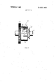
- FIG. 2 is an enlarged elevation view, partly broken away and partly in section, of a drive subassembly of the drive unit and additionally showing a schematic representation of an electrical circuit of the gasoline delivery pump;
- FIG. 3 is a side view, partly broken away and partly in section, of a clutch of the drive assembly.
- a gasoline delivery pump incorporating an embodiment 12 of a drive unit of the present invention comprising a delivery register 14 (for example of the type disclosed in US. Pat. No. 3,2 16,659 of Edward C. Ambler et al. dated Nov. 9, I965 and entitled Resetting Control Mechanism For Counting Device") having volume and cost counters 15, 16 respectively for registering the volume and cost of each fuel delivery and a reset shaft 17 adapted to be rotated one revolution (e.g., in the clockwise direction as viewed from the right side of the register 14 as viewed in FIG. 1) prior to the commencement of each fluid delivery for resetting the volume and cost counters l5, 16 to 0.
- a delivery register 14 for example of the type disclosed in US. Pat. No. 3,2 16,659 of Edward C. Ambler et al. dated Nov. 9, I965 and entitled Resetting Control Mechanism For Counting Device
- volume and cost counters 15, 16 respectively for registering the volume and cost of each fuel delivery
- a reset shaft 17 adapted to be rotate
- An auxiliary ticket printer 18 (for example of the type disclosed in US Pat. No. 3,478,854 of Lawrence Dilger et al. dated Nov. 18, 1969 and entitled Fuel Dispensing Apparatus Control System") is shown mounted directly above the register 14.
- the printer 18 has suitable volume and cost printing counters (not shown) which are suitably connected to be driven with the register volume and cost counters 15, 16 respectively for producing a printout of the volume and cost of each fuel delivery.
- a printer operating shaft 26 is adapted to be rotated one revolution (e.g., in the clockwise direction as viewed from the right side of the printer as viewed in FIG. 1)
- a fuel pump 32 driven by an electric motor 34 is provided for delivering gasoline from a suitable source through a fluid meter 35 to a dispensing nozzle 36 (which may be located on either side of the pump as shown by the alternatives shown in full and broken lines in FIG. 1).
- the output or volume shaft 40 of the meter 35 is connected for driving the volume counter 15 for registering the volume of the fuel delivered and for driving a variator 42 (for example of the type disclosed and described in US. Pat. No. 3,4 l 3,867 of Richard B. Hamlin dated Dec. 3, I968 and entitled Variator").
- the variator 42 is connected for driving the cost counter 16 for registering the cost of the fuel delivered in accordance with the volume of fuel dispensed and a unit volume price established by the variator setting.
- the drive unit 12 may, for example, be mounted on the same side of the delivery pump 10 as the nozzle 36 as shown by two alternative locations of the drive unit 12 shown in full and broken lines in FIG. 1.
- the drive unit comprises a two-part explosion-proof housing 60 with a receptacle 62 and a cover plate 64 (detachably fixed to the receptacle 62 by machine screws 66) and a reversible drive subassembly 70 with a support frame 71 detachably secured to three integral bosses 72-74 of the receptacle 62.
- the drive subassembly 70 has a pair of laterally spaced parallel drive shafts 78, 80, and a pair of coupling shafts 84, 86 are rotatably mounted in the cover plate 64 coaxially with the drive shafts 78, respectively.
- the coupling shafts 84, 86 have inner coupling members 87 for receiving the flattened ends of the drive shafts 78, 80 respectively for coupling the coaxial shafts 78, 84 and 80, 86 together when the cover plate 64 is mounted onto the receptacle 62.
- the upper coupling shaft 84 is shown coupled directly to the register reset shaft 17 for resetting the register prior to the commencement of each fuel delivery and the lower coupling shaft 86 is-shown connected to the printer operating shaft 26 by a belt drive 89 for operating the printer after the completion of each fuel delivery.
- a control shaft 90 is rotatably mounted in the housing receptacle 62 coaxially with the upper drive shaft 78, and an operating cam 92 is mounted on the inner end of the control shaft 90 for controlling the operation of the drive subassembly 70 as hereinafter described.
- the control shaft 90 is adapted to be coupled to an operating handle shown associated with a nozzle storage receptacle 102 for the nozzle 36.
- the operating handle 100 has to be turned to its vertical or Off" position shown in FIG. 1 (e.g., 90 in the clockwise direction in both locations of the operating handle 100 shown in full and broken lines in FIG.
- the handle 100 provides a manual input to the gasoline delivery pump 10, and the control shaft 90 and cam 92 are angularly reciprocable by the handle 100 between On" and Off angular positions thereof for controlling the operation of the gasoline delivery pump 10 as hereinafter more fully described.
- the support frame 71 of the drive subassembly 70 has three mounting apertures 103-105 for mounting the drive subassembly (to the bosses 72-74) in either of two reverse operating positions having a common center line 106 extending through the axis of the upper drive shaft 78.
- the reverse operating positions of the upper drive shaft 78 are coaxial and the coupling shaft 84 is adapted to be coupled to the drive shaft 78 in either reverse operating position thereof when the cover plate 64 is placed onto the receptacle 62.
- the lower drive shaft 80 is, however, laterally offset from the common center line 106, and the cover plate 64 is provided with a pair of laterally spaced bosses 108, 109 for mounting the lower coupling shaft 86 coaxially with the lower drive shaft 80 in either reverse operating position thereof.
- the unused boss 108, 109 is suitably plugged or is not bored to maintain the housing 60 explosion-proof.
- the cam 92 is contoured to be selectively mounted on the control shaft 90 (in either of two reverse positions having a common center line parallel to the center line 106) in accordance with the established operating position of the drive subassembly 70.
- the drive subassembly 70 comprises an electrical drive motor 110 connected for rotating the drive shafts 78 and 80 via gears 111-117 and substantially identical clutches 118, 1 19 respectively.
- the motor 1 is connected for rotating the drive shafts 78, 80 in the clockwise direction as viewed in FIG. 2 and for rotating the upper and lower coupling shafts 84, 86 in one angular direction in one reverse operating position of the drive subassembly 70 and in the other angular direction in the other reverse operating position of the drive subassembly 70.
- the coupling shafts 84, 86 can be selectively driven in either direction of rotation.
- the drive unit 12 is mounted on the right side of the pump 10 as viewed in FIG. 1, it would be preferable to rotate the coupling shafts 84, 86 in the clockwise angular direction as viewed from the operating handle 100, whereas, if the drive unit 12 is mounted on the left side of the pump as viewed in FIG. 1, it would be preferable to mount the drive subassembly 70 to rotate the coupling shafts 84, 86 in the counterclockwise direction as viewed from the operating handle 100.
- Each of the clutches 118, 119 comprises a drive sleeve 122 fixed to the respective drive gear 116, 117, a helical clutch spring 124 having one end fixed for rotation with the respective drive shaft 78, 80 and its other end connected to a rotatable clutch release collar 126.
- the helical clutch spring 124 is preloaded to engage the drive sleeve 122 for engaging the clutch and the release collar 126 is provided with a radial abutment or flange 128 for holding the release collar 126 against rotation and for thereby rotating the clutch spring 124 for releasing the clutch.
- three switches 130, 132, 134 are provided for (a) energizing the drive motor 110 through a first phase of motor operation prior to the commencement of each fuel delivery (for rotating the reset drive shaft 78 for resetting the register 14), (b) energizing the drive motor 110 through a second phase of motor operation after the completion of each fuel delivery (for rotating the auxiliary drive shaft 80 for operating the printer 18), and (c) energizing the pump motor 34 for conditioning the pump 10 for delivering gasoline.
- a switch operating cam 136 (fixed for rotation with the reset clutch release collar 126) functions to hold a lever 138 outwardly against the bias of a tension spring 139 to hold switch 130 in its closed position as shown in FIG. 2 for maintaining the pump motor 34 de-energized between fuel deliveries.
- a pivotal lever 140 having a cam follower or pin 142 engageable with the control cam 92 (and extending in both axial directions for engagement with the control cam 92 in both reverse operating positions of the drive subassembly 70) is freed to be pivoted approximately in the clockwise direction as viewed in FIG. 2, by a tension spring 146.
- a primary clutch control lever 148 is thereby pivoted in the counterclockwise direction as viewed in FIG. 2 (the pin 142 being received in an elongated slot 150 in lever 148 for pivoting the lever), to close" the switch 132 and energize the drive motor 110.
- a secondary clutch control lever 156 fixed for rotation with the lever 140 is pivoted to withdraw its shoulder 157 out of engagement with the reset clutch operating flange 128 to re-engage the reset drive clutch 118 for rotating the reset drive shaft 78 with the drive motor 110.
- a second switch operating cam 160 (also fixed for rotation with the reset clutch release collar 126) provides for holding the switch 132 closed" after the reset clutch 118 is re-engaged for ensuring that the first phase of operation of the reset motor 110 is completed (to completely reset the register 14) even though the operating handle 100 is only momentarily held in its On" position.
- the primary clutch control lever 148 is withdrawn from the auxiliary drive clutch 119 for rotating the auxiliary drive shaft approximately 10 until the auxiliary clutch operating flange 128 engages a shoulder 168 of the secondary clutch clutch control lever 156 to disengage the auxiliary drive clutch 119.
- the printer operating shaft 26 is connected to the printer to permit corresponding l0 rotation of the printer operating shaft 26 without effecting operation of the printer 18.
- the drive subassembly 70 remains in this condition during any succeeding delivery of gasoline.
- the drive motor 110 is maintained energized by the switch 134 until the auxiliary clutch operating flange 128 engages the flange 164 of the primary clutch control lever 148 at which point the auxiliary drive shaft clutch 119 is disengaged and the switch 134 is opened” by its operating cam 174 (which is connected for rotation with the auxiliary clutch release collar 126) to de-energize the drive motor 110 and thereby terminate the second phase of operation of the drive motor.
- the drive subassembly 70 remains in this condition between fuel deliveries (until the operating handle 100 is returned to its On" position).
- the drive subassembly 70 is adapted to be operated through a first phase of operation for resetting the register 14 prior to the commencement of each fuel delivery and to be operated through a second phase of operation for operating the printer 18 after the completion of each fuel delivery.
- a drive unit comprising a drive motor, a reset drive clutch having a rotary input driven by the drive motor and a rotary output for connection to the register reset shaft and engageable for resetting the register, an auxiliary drive clutch having a rotary input driven by the drive motor and a rotary output for connection to the auxiliary shaft and engageable for operating the auxiliary apparatus through its operating cycle, each of said clutches having a rotary clutch operating member rotatable with the rotary output of the clutch and adapted to be locked against rotation for disengaging the clutch, and a clutch operating mechanism for normally locking the clutch operating members against rotation and selectively operable for temporarily unlocking each clutch operating member for rotation through a predetermined angle thereof for selectively resetting the register and operating the auxiliary apparatus through its operating cycle.
- a drive unit comprising reciprocable means operable between first and second operating positions thereof, the reciprocable means when operated from its first to its second operating position being operable for temporarily unlocking the reset drive clutch operating member for rotation through a first predetermined angle thereof for resetting the register and when operated from its second to its first operating position being operable for temporarily unlocking the auxiliary drive clutch operating member for rotation through a first predetermined angle thereof for operating the auxiliary apparatus through its operating cycle.
- a drive unit according to claim 2 wherein the reciprocable means when operated from its second to its first operating position is operable for temporarily unlocking the reset drive clutch operating member for rotation through a second predetermined angle thereof.
- a drive unit wherein the reciprocable means when operated from its first to its second operating position is operable for temporarily unlocking the auxiliary drive clutch operating member for rotation through a second predetermined angle thereof.
- a drive unit according to claim 3 wherein said first and second predetermined angles of rotation of the reset drive clutch operating member total 360.
- a drive unit wherein the drive motor is an electrical drive motor and further comprising switch means operable by the reciprocable means when operated to each operating position thereof for energizing the drive motor and first and second switch operators rotatable with the rotary outputs of the reset and auxiliary drive clutches respectively for operating the switch means for de-energizing the electrical motor at the completion of said first predetermined angles of rotation of the reset and auxiliary drive clutch operating members respectively.
Landscapes
- Engineering & Computer Science (AREA)
- Physics & Mathematics (AREA)
- Mathematical Physics (AREA)
- Theoretical Computer Science (AREA)
- Mechanical Engineering (AREA)
- Reciprocating Pumps (AREA)
Abstract
A gasoline delivery pump with a resettable delivery register, a ticket printer mounted above the register operable for recording the amount of each fluid delivery and a two-phase drive unit having a first drive shaft connected to a register reset shaft for resetting the register to ''''0'''' prior to the commencement of each fuel delivery and a second drive shaft connected for operating the printer after the completion of each fluid delivery. The drive unit comprises an electrical drive subassembly adapted to be selectively mounted in an explosionproof housing in either of two reverse positions for selectively rotating the drive shafts in either direction of rotation for facilitating selectively mounting the drive unit on either side of the register.
Description
United States Patent Conte' [is] 3,662,866 51 May 16,1972
DRIVE UNIT FOR FLUID DELIVERY PUMP Inventor: Silvio Conte, East Hartford, Conn.
Veeder Industries Inc., Hartford, Conn.
Sept. 14, 1970 Assignee:
Filed:
Appl. No.:
U.S. Cl ..l92/.02, 192/26, 192/489, 222/30, 222/33, 235/144 D, 346/43 Int. Cl. ..Fl6d 13/10, 867d 5/24, G06c 15/42 Field of Search 192/.02, 26, 48.9; 222/30, 222/33; 235/144 D; 346/43 References Cited UNITED STATES PATENTS 2/1962 Swank ..222/33X 2/1962 Robinson,Jr ..222/30 3,434,155 3/1969 Copony et al ..222/30 Primary ExaminerAllan D. l-lerrmann Attorney-Prutzman, Hayes, Kalb & Chilton [57] ABSTRACT A gasoline delivery pump with a resettable delivery register, a ticket printer mounted above the register operable for recording the amount of each fluid delivery and a two-phase drive unit having a first drive shaft connected to a register reset shaft for resetting the register to 0" prior to the commence-- 6 Claims, 3 Drawing Figures PATENTEBMAY 16 I972 SHEET 1 0F 3 EHZEQ INVENTOR SILVIO CONTE lav/W73? ATTORNEYS PATENTEDHAY 16 In 3 662.866
sum 3 OF 3 DRIVE UNIT FOR FLUID DELIVERY PUMP BRIEF SUMMARY OF THE INVENTION The present invention relates generally to fluid delivery pumps of the type conventionally employed for dispensing gasoline and more particularly to a new and improved drive unit for a fluid delivery pump.
It is a principal aim of the present invention to provide a new and improved drive unit for a gasoline delivery pump for resetting the delivery register conventionally employed in such pumps.
It is another aim of the present invention to provide a new and improved drive unit for resetting the delivery register of a fluid deliver pump and which'is reversible for facilitating mounting the drive unit on either side of the delivery register.
It is a further aim of the present invention to provide a new and improved drive unit for resetting the delivery register of a fluid delivery pump prior to the commencement of each fluid delivery and for operating auxiliary apparatus of the fluid delivery pump after the completion of each fluid delivery.
It is another aim of the present invention to provide a new and improved drive unit for resetting the register of a fluid delivery pump prior to the commencement of each fluid delivery and for operating a printer of the fluid delivery pump after the completion of each fluid delivery for providing a printout of the amount of fluid delivered.
Other objects will be in part obvious and in more in detail hereinafter.
A better understanding of the invention will be obtained from the following detailed description and the accompanying drawings of an illustrative application of the invention.
BRIEF DESCRIPTION OF THE DRAWINGS In the drawings:
FIG. 1 is a generally schematic representation, partly broken away, of a gasoline delivery pump incorporating an embodiment of a drive unit of the present invention and show ing the drive unit in full lines on one side of the pump and in broken lines in an alternate location on the other side of the P p FIG. 2 is an enlarged elevation view, partly broken away and partly in section, of a drive subassembly of the drive unit and additionally showing a schematic representation of an electrical circuit of the gasoline delivery pump; and
FIG. 3 is a side view, partly broken away and partly in section, of a clutch of the drive assembly.
part pointed out DESCRIPTION OF THE PREFERRED EMBODIMENT Referring now to the drawings in detail wherein like numerals represent like parts, a gasoline delivery pump incorporating an embodiment 12 of a drive unit of the present invention is shown comprising a delivery register 14 (for example of the type disclosed in US. Pat. No. 3,2 16,659 of Edward C. Ambler et al. dated Nov. 9, I965 and entitled Resetting Control Mechanism For Counting Device") having volume and cost counters 15, 16 respectively for registering the volume and cost of each fuel delivery and a reset shaft 17 adapted to be rotated one revolution (e.g., in the clockwise direction as viewed from the right side of the register 14 as viewed in FIG. 1) prior to the commencement of each fluid delivery for resetting the volume and cost counters l5, 16 to 0.
An auxiliary ticket printer 18 (for example of the type disclosed in US Pat. No. 3,478,854 of Lawrence Dilger et al. dated Nov. 18, 1969 and entitled Fuel Dispensing Apparatus Control System") is shown mounted directly above the register 14. The printer 18 has suitable volume and cost printing counters (not shown) which are suitably connected to be driven with the register volume and cost counters 15, 16 respectively for producing a printout of the volume and cost of each fuel delivery. A printer operating shaft 26 is adapted to be rotated one revolution (e.g., in the clockwise direction as viewed from the right side of the printer as viewed in FIG. 1)
after the completion of each fuel delivery for producing a printout of the cost and volume of the fuel delivery and for thereafter resetting the volume and cost printing counters (not shown) to 0".
In a conventional manner a fuel pump 32 driven by an electric motor 34 is provided for delivering gasoline from a suitable source through a fluid meter 35 to a dispensing nozzle 36 (which may be located on either side of the pump as shown by the alternatives shown in full and broken lines in FIG. 1). The output or volume shaft 40 of the meter 35 is connected for driving the volume counter 15 for registering the volume of the fuel delivered and for driving a variator 42 (for example of the type disclosed and described in US. Pat. No. 3,4 l 3,867 of Richard B. Hamlin dated Dec. 3, I968 and entitled Variator"). The variator 42 is connected for driving the cost counter 16 for registering the cost of the fuel delivered in accordance with the volume of fuel dispensed and a unit volume price established by the variator setting.
The drive unit 12 may, for example, be mounted on the same side of the delivery pump 10 as the nozzle 36 as shown by two alternative locations of the drive unit 12 shown in full and broken lines in FIG. 1.
The drive unit comprises a two-part explosion-proof housing 60 with a receptacle 62 and a cover plate 64 (detachably fixed to the receptacle 62 by machine screws 66) and a reversible drive subassembly 70 with a support frame 71 detachably secured to three integral bosses 72-74 of the receptacle 62. The drive subassembly 70 has a pair of laterally spaced parallel drive shafts 78, 80, and a pair of coupling shafts 84, 86 are rotatably mounted in the cover plate 64 coaxially with the drive shafts 78, respectively. The coupling shafts 84, 86 have inner coupling members 87 for receiving the flattened ends of the drive shafts 78, 80 respectively for coupling the coaxial shafts 78, 84 and 80, 86 together when the cover plate 64 is mounted onto the receptacle 62.
The upper coupling shaft 84 is shown coupled directly to the register reset shaft 17 for resetting the register prior to the commencement of each fuel delivery and the lower coupling shaft 86 is-shown connected to the printer operating shaft 26 by a belt drive 89 for operating the printer after the completion of each fuel delivery.
A control shaft 90 is rotatably mounted in the housing receptacle 62 coaxially with the upper drive shaft 78, and an operating cam 92 is mounted on the inner end of the control shaft 90 for controlling the operation of the drive subassembly 70 as hereinafter described. The control shaft 90 is adapted to be coupled to an operating handle shown associated with a nozzle storage receptacle 102 for the nozzle 36. In a conventional manner the operating handle 100 has to be turned to its vertical or Off" position shown in FIG. 1 (e.g., 90 in the clockwise direction in both locations of the operating handle 100 shown in full and broken lines in FIG. I) to replace the nozzle 36 in its storage receptacle 102, and the nozzle 36 has to be removed from its storage receptacle 102 to permit turning the operating handle 100 in the opposite direction to its horizontal or On position. Also the handle 100 provides a manual input to the gasoline delivery pump 10, and the control shaft 90 and cam 92 are angularly reciprocable by the handle 100 between On" and Off angular positions thereof for controlling the operation of the gasoline delivery pump 10 as hereinafter more fully described.
. The support frame 71 of the drive subassembly 70 has three mounting apertures 103-105 for mounting the drive subassembly (to the bosses 72-74) in either of two reverse operating positions having a common center line 106 extending through the axis of the upper drive shaft 78. The reverse operating positions of the upper drive shaft 78 are coaxial and the coupling shaft 84 is adapted to be coupled to the drive shaft 78 in either reverse operating position thereof when the cover plate 64 is placed onto the receptacle 62. The lower drive shaft 80 is, however, laterally offset from the common center line 106, and the cover plate 64 is provided with a pair of laterally spaced bosses 108, 109 for mounting the lower coupling shaft 86 coaxially with the lower drive shaft 80 in either reverse operating position thereof. The unused boss 108, 109 is suitably plugged or is not bored to maintain the housing 60 explosion-proof. Also, the cam 92 is contoured to be selectively mounted on the control shaft 90 (in either of two reverse positions having a common center line parallel to the center line 106) in accordance with the established operating position of the drive subassembly 70.
The drive subassembly 70 comprises an electrical drive motor 110 connected for rotating the drive shafts 78 and 80 via gears 111-117 and substantially identical clutches 118, 1 19 respectively. The motor 1 is connected for rotating the drive shafts 78, 80 in the clockwise direction as viewed in FIG. 2 and for rotating the upper and lower coupling shafts 84, 86 in one angular direction in one reverse operating position of the drive subassembly 70 and in the other angular direction in the other reverse operating position of the drive subassembly 70. Thus, by selectively mounting the drive subassembly 70 within the explosion-proof housing 60 and by appropriately mounting the control cam 92 on the control shaft 90 and the lower coupling shaft 86 on the cover plate 64, the coupling shafts 84, 86 can be selectively driven in either direction of rotation. For example, if the drive unit 12 is mounted on the right side of the pump 10 as viewed in FIG. 1, it would be preferable to rotate the coupling shafts 84, 86 in the clockwise angular direction as viewed from the operating handle 100, whereas, if the drive unit 12 is mounted on the left side of the pump as viewed in FIG. 1, it would be preferable to mount the drive subassembly 70 to rotate the coupling shafts 84, 86 in the counterclockwise direction as viewed from the operating handle 100.
Each of the clutches 118, 119 comprises a drive sleeve 122 fixed to the respective drive gear 116, 117, a helical clutch spring 124 having one end fixed for rotation with the respective drive shaft 78, 80 and its other end connected to a rotatable clutch release collar 126. The helical clutch spring 124 is preloaded to engage the drive sleeve 122 for engaging the clutch and the release collar 126 is provided with a radial abutment or flange 128 for holding the release collar 126 against rotation and for thereby rotating the clutch spring 124 for releasing the clutch.
Referring particularly to FIG. 2, three switches 130, 132, 134 are provided for (a) energizing the drive motor 110 through a first phase of motor operation prior to the commencement of each fuel delivery (for rotating the reset drive shaft 78 for resetting the register 14), (b) energizing the drive motor 110 through a second phase of motor operation after the completion of each fuel delivery (for rotating the auxiliary drive shaft 80 for operating the printer 18), and (c) energizing the pump motor 34 for conditioning the pump 10 for delivering gasoline. A switch operating cam 136 (fixed for rotation with the reset clutch release collar 126) functions to hold a lever 138 outwardly against the bias of a tension spring 139 to hold switch 130 in its closed position as shown in FIG. 2 for maintaining the pump motor 34 de-energized between fuel deliveries.
When the operating handle 100 is rotated to its horizontal or On position, a pivotal lever 140 having a cam follower or pin 142 engageable with the control cam 92 (and extending in both axial directions for engagement with the control cam 92 in both reverse operating positions of the drive subassembly 70) is freed to be pivoted approximately in the clockwise direction as viewed in FIG. 2, by a tension spring 146. A primary clutch control lever 148 is thereby pivoted in the counterclockwise direction as viewed in FIG. 2 (the pin 142 being received in an elongated slot 150 in lever 148 for pivoting the lever), to close" the switch 132 and energize the drive motor 110. At the same time a secondary clutch control lever 156 fixed for rotation with the lever 140 is pivoted to withdraw its shoulder 157 out of engagement with the reset clutch operating flange 128 to re-engage the reset drive clutch 118 for rotating the reset drive shaft 78 with the drive motor 110. A second switch operating cam 160 (also fixed for rotation with the reset clutch release collar 126) provides for holding the switch 132 closed" after the reset clutch 118 is re-engaged for ensuring that the first phase of operation of the reset motor 110 is completed (to completely reset the register 14) even though the operating handle 100 is only momentarily held in its On" position.
After approximately 335 of rotation of the reset drive shaft 78 (in the clockwise direction as viewed in FIG. 2) (a) the switch operating cam 136 releases the lever 138 for opening" the switch 130 for de-energizing the drive motor 110 and energizing the pump motor 34, and (b) the reset clutch operating flange 128 engages an inwardly projecting flange 164 of the primary clutch control lever 148 to disengage the reset clutch 118.
Also, when the operating handle 100 is pivoted to its horizontal or On" position, the primary clutch control lever 148 is withdrawn from the auxiliary drive clutch 119 for rotating the auxiliary drive shaft approximately 10 until the auxiliary clutch operating flange 128 engages a shoulder 168 of the secondary clutch clutch control lever 156 to disengage the auxiliary drive clutch 119. The printer operating shaft 26 is connected to the printer to permit corresponding l0 rotation of the printer operating shaft 26 without effecting operation of the printer 18. The drive subassembly 70 remains in this condition during any succeeding delivery of gasoline.
When the operating handle is rotated to its vertical or Off" position (a) the control cam 92 engages a flange 170 (extending in both axial directions for engagement by the cam 92 in both reverse operating positions of the drive subassembly 70) to de-energize the pump motor 34 and energize the drive motor (the switch 132 having been previously closed during the first phase of motor operation by its operating cam 160), (b) the secondary clutch control lever 156 is retracted from the auxiliary drive clutch 119 for rotating the auxiliary drive shaft 80 approximately 350 (until the auxiliary clutch operating flange 128 engages the flange 164 of the primary clutch control lever 148), and (c) the primary clutch control lever 148 is retracted from the reset drive clutch 118 for rotating the reset drive shaft approximately 25 (until the reset clutch operating flange 128 engages the shoulder 157 of the secondary clutch control lever 156) to its Off position shown in FIG. 1 to hold the switch closed and to open the switch 132. (The reset mechanism of the register 14 is designed such that the corresponding 25 rotation of the register reset shaft 17 does not effect operation of the reset mechanism). The drive motor 110 is maintained energized by the switch 134 until the auxiliary clutch operating flange 128 engages the flange 164 of the primary clutch control lever 148 at which point the auxiliary drive shaft clutch 119 is disengaged and the switch 134 is opened" by its operating cam 174 (which is connected for rotation with the auxiliary clutch release collar 126) to de-energize the drive motor 110 and thereby terminate the second phase of operation of the drive motor. The drive subassembly 70 remains in this condition between fuel deliveries (until the operating handle 100 is returned to its On" position).
Thus, the drive subassembly 70 is adapted to be operated through a first phase of operation for resetting the register 14 prior to the commencement of each fuel delivery and to be operated through a second phase of operation for operating the printer 18 after the completion of each fuel delivery.
As will be apparent to persons skilled in the art, various modifications, adaptations and variations of the foregoing specific disclosure can be made without departing from the teachings of the present invention.
Iclaim:
1. For use in fluid delivery apparatus having a resettable delivery register with a reset shaft rotatable for resetting the register and an auxiliary apparatus with an auxiliary shaft rotatable for operating the auxiliary apparatus through an operating cycle thereof; a drive unit comprising a drive motor, a reset drive clutch having a rotary input driven by the drive motor and a rotary output for connection to the register reset shaft and engageable for resetting the register, an auxiliary drive clutch having a rotary input driven by the drive motor and a rotary output for connection to the auxiliary shaft and engageable for operating the auxiliary apparatus through its operating cycle, each of said clutches having a rotary clutch operating member rotatable with the rotary output of the clutch and adapted to be locked against rotation for disengaging the clutch, and a clutch operating mechanism for normally locking the clutch operating members against rotation and selectively operable for temporarily unlocking each clutch operating member for rotation through a predetermined angle thereof for selectively resetting the register and operating the auxiliary apparatus through its operating cycle.
2. A drive unit according to claim 1 wherein the clutch operating mechanism comprises reciprocable means operable between first and second operating positions thereof, the reciprocable means when operated from its first to its second operating position being operable for temporarily unlocking the reset drive clutch operating member for rotation through a first predetermined angle thereof for resetting the register and when operated from its second to its first operating position being operable for temporarily unlocking the auxiliary drive clutch operating member for rotation through a first predetermined angle thereof for operating the auxiliary apparatus through its operating cycle.
3. A drive unit according to claim 2 wherein the reciprocable means when operated from its second to its first operating position is operable for temporarily unlocking the reset drive clutch operating member for rotation through a second predetermined angle thereof.
4. A drive unit according to claim 3 wherein the reciprocable means when operated from its first to its second operating position is operable for temporarily unlocking the auxiliary drive clutch operating member for rotation through a second predetermined angle thereof.
5. A drive unit according to claim 3 wherein said first and second predetermined angles of rotation of the reset drive clutch operating member total 360.
6. A drive unit according to claim 2 wherein the drive motor is an electrical drive motor and further comprising switch means operable by the reciprocable means when operated to each operating position thereof for energizing the drive motor and first and second switch operators rotatable with the rotary outputs of the reset and auxiliary drive clutches respectively for operating the switch means for de-energizing the electrical motor at the completion of said first predetermined angles of rotation of the reset and auxiliary drive clutch operating members respectively.
Claims (6)
1. For use in fluid delivery apparatus having a resettable delivery register with a reset shaft rotatable for resetting the register and an auxiliary apparatus with an auxiliary shaft rotatable for operating the auxiliary apparatus through an operating cycle thereof; a drive unit comprising a drive motor, a reset drive clutch having a rotary input driven by the drive motor and a rotary output for connection to the register reset shaft and engageable for resetting the register, an auxiliary drive clutch having a rotary input driven by the drive motor and a rotary output for connection to the auxiliary shaft and engageable for operating the auxiliary apparatus through its operating cycle, each of said clutches having a rotary clutch operating member rotatable with the rotary output of the clutch and adapted to be locked against rotation for disengaging the clutch, and a clutch operating mechanism for normally locking the clutch operating members against rotation and selectively operable for temporarily unlocking each clutch operating member for rotation through a predetermined angle thereof for selectively resetting the register and operating the auxiliary apparatus through its operating cycle.
2. A drive unit according to claim 1 wherein the clutch operating mechanism comprises reciprocable means operable between first and second operating positions thereof, the reciprocable means when operated from its first to its second operating position being operable for temporarily unlocking the reset drive clutch operating member for rotation through a first predetermined angle thereof for resetting the register and when operated from its second to its first operating position being operable for temporarily unlocking the auxiliary drive clutch operating member for rotation through a first predetermined angle thereof for operating the auxiliary apparatus through its operating cycle.
3. A drive unit according to claim 2 wherein the reciprocable means when operated from its second to its first operating position is operable for temporarily unlocking the reset drive clutch operatiNg member for rotation through a second predetermined angle thereof.
4. A drive unit according to claim 3 wherein the reciprocable means when operated from its first to its second operating position is operable for temporarily unlocking the auxiliary drive clutch operating member for rotation through a second predetermined angle thereof.
5. A drive unit according to claim 3 wherein said first and second predetermined angles of rotation of the reset drive clutch operating member total 360* .
6. A drive unit according to claim 2 wherein the drive motor is an electrical drive motor and further comprising switch means operable by the reciprocable means when operated to each operating position thereof for energizing the drive motor and first and second switch operators rotatable with the rotary outputs of the reset and auxiliary drive clutches respectively for operating the switch means for de-energizing the electrical motor at the completion of said first predetermined angles of rotation of the reset and auxiliary drive clutch operating members respectively.
Applications Claiming Priority (1)
| Application Number | Priority Date | Filing Date | Title |
|---|---|---|---|
| US7199770A | 1970-09-14 | 1970-09-14 |
Publications (1)
| Publication Number | Publication Date |
|---|---|
| US3662866A true US3662866A (en) | 1972-05-16 |
Family
ID=22104909
Family Applications (1)
| Application Number | Title | Priority Date | Filing Date |
|---|---|---|---|
| US71997A Expired - Lifetime US3662866A (en) | 1970-09-14 | 1970-09-14 | Drive unit for fluid delivery pump |
Country Status (1)
| Country | Link |
|---|---|
| US (1) | US3662866A (en) |
Cited By (1)
| Publication number | Priority date | Publication date | Assignee | Title |
|---|---|---|---|---|
| US3951307A (en) * | 1973-07-11 | 1976-04-20 | Kienzle Apparate Gmbh | Timing of the control and resetting motor in a fuel dispensing arrangement |
Citations (3)
| Publication number | Priority date | Publication date | Assignee | Title |
|---|---|---|---|---|
| US3021032A (en) * | 1958-09-02 | 1962-02-13 | Smith Corp A O | Fuel dispensing unit |
| US3021982A (en) * | 1959-12-23 | 1962-02-20 | Gilbert & Barker Mfg Co | Computer-printer interlock apparatus |
| US3434155A (en) * | 1966-09-09 | 1969-03-18 | Symington Wayne Corp | Ticket printing device for dispenser |
-
1970
- 1970-09-14 US US71997A patent/US3662866A/en not_active Expired - Lifetime
Patent Citations (3)
| Publication number | Priority date | Publication date | Assignee | Title |
|---|---|---|---|---|
| US3021032A (en) * | 1958-09-02 | 1962-02-13 | Smith Corp A O | Fuel dispensing unit |
| US3021982A (en) * | 1959-12-23 | 1962-02-20 | Gilbert & Barker Mfg Co | Computer-printer interlock apparatus |
| US3434155A (en) * | 1966-09-09 | 1969-03-18 | Symington Wayne Corp | Ticket printing device for dispenser |
Cited By (1)
| Publication number | Priority date | Publication date | Assignee | Title |
|---|---|---|---|---|
| US3951307A (en) * | 1973-07-11 | 1976-04-20 | Kienzle Apparate Gmbh | Timing of the control and resetting motor in a fuel dispensing arrangement |
Similar Documents
| Publication | Publication Date | Title |
|---|---|---|
| US2137013A (en) | Register with preset trip mechanism | |
| US3027048A (en) | Liquid dispensing apparatus and remote register means therefor | |
| US3662866A (en) | Drive unit for fluid delivery pump | |
| US3603481A (en) | Fluid-dispensing apparatus control system | |
| US3216659A (en) | Resetting control mechanism for counting device | |
| US3142442A (en) | Resetting mechanism for counters | |
| US2109352A (en) | Automatic zeroizer for dispensing pump | |
| US2327584A (en) | Liquid dispensing device | |
| US4223807A (en) | Multiple product gasoline dispenser | |
| US2305221A (en) | Predetermining apparatus for liquid dispensing pumps | |
| US3021032A (en) | Fuel dispensing unit | |
| US2665030A (en) | Preselector mechanism for liquid dispensing apparatus | |
| US3668375A (en) | Printer | |
| US3688291A (en) | Electrical unit for fuel delivery pump | |
| US2524755A (en) | Predeterminator register mechanism | |
| US3344987A (en) | Interlock for a metering and recording unit | |
| US3392882A (en) | Counter reset operating mechanism | |
| US2311905A (en) | Control mechanism for motor driven fluid measuring apparatus | |
| GB1158021A (en) | Fluid Dispensing Apparatus Control System | |
| GB965694A (en) | Improvements in or relating to liquid dispensers | |
| US3332619A (en) | Counter reset mechanism | |
| US2833477A (en) | Resetting mechanism for counters | |
| US3618823A (en) | Fuel dispenser power resetting and control mechanism | |
| US3675848A (en) | Variator | |
| GB908977A (en) | Improvements in or relating to control mechanism for liquid dispensers |