US3671167A - Incinerator for waste oil and the like - Google Patents
Incinerator for waste oil and the like Download PDFInfo
- Publication number
- US3671167A US3671167A US106743A US3671167DA US3671167A US 3671167 A US3671167 A US 3671167A US 106743 A US106743 A US 106743A US 3671167D A US3671167D A US 3671167DA US 3671167 A US3671167 A US 3671167A
- Authority
- US
- United States
- Prior art keywords
- combustion chamber
- waste oil
- air
- rotary cylinder
- incinerator
- Prior art date
- Legal status (The legal status is an assumption and is not a legal conclusion. Google has not performed a legal analysis and makes no representation as to the accuracy of the status listed.)
- Expired - Lifetime
Links
Images
Classifications
-
- F—MECHANICAL ENGINEERING; LIGHTING; HEATING; WEAPONS; BLASTING
- F23—COMBUSTION APPARATUS; COMBUSTION PROCESSES
- F23G—CREMATION FURNACES; CONSUMING WASTE PRODUCTS BY COMBUSTION
- F23G7/00—Incinerators or other apparatus for consuming industrial waste, e.g. chemicals
- F23G7/05—Incinerators or other apparatus for consuming industrial waste, e.g. chemicals of waste oils
-
- F—MECHANICAL ENGINEERING; LIGHTING; HEATING; WEAPONS; BLASTING
- F23—COMBUSTION APPARATUS; COMBUSTION PROCESSES
- F23G—CREMATION FURNACES; CONSUMING WASTE PRODUCTS BY COMBUSTION
- F23G5/00—Incineration of waste; Incinerator constructions; Details, accessories or control therefor
- F23G5/24—Incineration of waste; Incinerator constructions; Details, accessories or control therefor having a vertical, substantially cylindrical, combustion chamber
- F23G5/28—Incineration of waste; Incinerator constructions; Details, accessories or control therefor having a vertical, substantially cylindrical, combustion chamber having raking arms
-
- F—MECHANICAL ENGINEERING; LIGHTING; HEATING; WEAPONS; BLASTING
- F23—COMBUSTION APPARATUS; COMBUSTION PROCESSES
- F23G—CREMATION FURNACES; CONSUMING WASTE PRODUCTS BY COMBUSTION
- F23G5/00—Incineration of waste; Incinerator constructions; Details, accessories or control therefor
- F23G5/50—Control or safety arrangements
Definitions
- the invention is concerned with an incinerator adapted to consume organic waste products of relatively high viscosity, such as used oil, tar, and pitch, hereinafter merely called waste oil, which would otherwise be difficult to completely burn because of its water and earth content.
- waste oil organic waste products of relatively high viscosity, such as used oil, tar, and pitch, hereinafter merely called waste oil, which would otherwise be difficult to completely burn because of its water and earth content.
- the burning is accomplished by the mixing of air with the waste oil to be incinerated while automatically controlling the air supply in response to the burning condition.
- An object of the invention is to provide an incinerator for disposing of waste products of the above type without creating air pollution problems.
- waste oil which tends to foul water and cause fire and odor.
- a difiiculty involved in waste oil is its incombustible property owing to water and earth content, these elements existing inseparably from the oil content, i.e., in the emulsive state.
- the basic idea of the present invention is that the waste oil is atomized by the jet of primary air, filling a combustion chamber with oil particles which are burned in a state of being well mixed with secondary and tertiary air.
- the air supply is automatically controlled and the remaining waste oil on the bottom is stirred at an adequate speed in accordance with the burning condition of the waste oil, thus accomplishing the constant mixture of air with the incinerating substance.
- This enables the substance to burn in a continuous and complete manner.
- the dirt or earth particles contained in the waste oil settles and may be removed, thereby providing no difiiculty in the combustion of the waste oil.
- an incinerator comprises a vertical combustion chamber with a pipe supplying the waste oil to be consumed.
- the pipe outlet is placed inside the combustion chamber and a rotary cylinder is provided at the center of the bottom floor of the combustion chamber.
- the cylinder has its upper end projecting into the combustion chamber.
- the cylindrical arms have on their underfaces vanes extending toward the bottom floor of the combustion chamber, and air outlet openings are provided along their full length.
- the side wall of the combustion chamber includes further air outlet openings.
- the controlling means is electrically connected to motors of blowers via an air-supply control circuit, thereby supplying air in an adequate amount in response to the burning condition of the waste oil.
- a means for controlling the rotating speed of the rotary cylinder is electrically connected to a motor for driving the rotary cylinder, the speed being in response to the burning condition of the waste oil, thereby ensuring the adequate stirring of the Waste oil at the bottom floor of the combustion chamber by means of the vanes of the cylindrical arms.
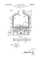
- the body of an incinerator 1 has a three-fold enclosure, i.e., an innermost combustion chamber 2, a middle water jacket 3 around the combustion chamber 2 to prevent possible overheating and an outermost third-air chamber 4.
- Waste oil to be incinerated is supplied into the combustion chamber 2 through an outlet 5A of a supply pipe 5 entering from outside the combustion chamber 2. Ash residue is discharged through an outlet 14 provided at the bottom of the combustion chamber, as near to its corner as possible.
- a bottom floor 6 of the combustion chamber is provided with a bearing 7 at its center, which rotatably supports a rotary cylinder 8 having its upper end extending into the combustion chamber 2.
- the upper end of the rotary cylinder 8 is provided with a number of radially extending cylindrical arms 9 positioned parallel to the bottom floor 6 of the combustion chamber 2.
- the rotary cylinder 8 and the cylindrical arms 9 communicate internally with one another, providing passages of primary and secondary air. Two types of air are blown into the passages by means of a pair of blowers 18 and 19.
- the blower 18 is connected to the rotary cylinder 8.
- the cylindrical arms 9 have vanes 12 secured to their underfaces. The vanes are spaced from each other and are positioned adjacent to the bottom floor 6.
- the arms 9 are provided with primary air outlets 10 and secondary air outlets 11.
- the former are directed diagonally downward, and the latter are directed diagonally upward.
- the side wall of the combustion chamber 2 is provided with third air outlets 15 communicating with the third air chamber 4, to which the tertiary air is transferred by means of a blower 18 or 19. In the example illustrated, it is blown by a blower 19.
- the blowers 18 and 19 are driven by D.C. motors 16 and 17, respectively, all of which are mounted at convenient locations under the combustion chamber 2.
- air is blown under pressure into the combustion chamber 2 through its respective route as primary, secondary and tertiary air.
- the DC. motors 16 and 17 are connected to an A.C. source 20 through a silicon controlled rectifier 21 and a full-wave rectifier 31.
- the gate 21A of the silicon controlled rectifier 21 is electrically connected to a photodiode 22 through a phase-reversing circuit 32.
- the photodiode 22 is mounted in the side Wall of the combustion chamber 2.
- Mounted opposite diode 22 is a light projector 23, diode 22 thereby electrically detecting the burning condition of the waste oil inside the combustion chamber 2 through changes in the strength of the light beam received from the projector 23.
- the rotary cylinder 8 is rotated by a motor 25 by means of a chain-and-sprocket unit 26.
- the motor 25 is a DC. speed-reduction motor, and is connected to an A.C. source 34 through another all-wave rectifying circuit 35 and a silicon controlled rectifier 36, the gate 36A of which is connected to a thermoelectric thermometer 37 provided at the ash discharging outlet 14.
- thermoelectric thermometer 37 a resistance thermometer or a bimetal can be of course used.
- thermoelectric thermometer 37 instead of detecting the temperature of ash residue, it is also possible to electrically examine the color of the flames brought about through the burning of the waste oil. This may be accomplished by placing a photoconductive cell or a photoelectric tube thermometer in the top wall of the combustion chamber 2 as shown by the imaginary line in FIG. 1, connected to the gate 36A of the silicon rectifier 36.
- Smoke, if any, is discharged from the combustion chamber 2 through a chimney 24.
- the burning condition of the waste oil is visually viewed through a window 27.
- the bottom floor of the combustion chamber 2 is covered with sand or ash 28.
- the motors 25, 16 and 17 are driven to actuate the rotary cylinder *8, and the blowers 18 and 19, respectively.
- a combustible agent such as light oil
- a valve (not shown) is switched to stop its supply, and to start the supply of waste oil to be incinerated.
- the waste oil falls, drop by drop, around the center of the bottom floor 6, where the waste oil is stirred by the vanes 12 of the rotating cylindrical arms 9, and is atomized by the jet of primary air. In the course of rising in the combustion chamber 2, the atomized waste oil is burned.
- the waste oil remaining on the bottom floor 6 is gradually conveyed to the corner of the bottom floor 6, creating eddies thereon. In the course of its conveyance it is substantially burned out, leaving solid carbon residue on the bottom floor 6, which is broken down into pieces by the vanes .12, and which is taken away from the oil surface. Finally, the residue is discharged out of the bottom floor 6 through the outlet 14. In this case, the temperature of the ash is examined by the thermoelectric thermometer 37, which is transmitted to the motor 25, thereby controlling its rotating speed to ensure the adequate stirring of the waste oil by the vanes 12.
- a photo-transistor or a photo-cell can be employed.
- waste oil successively supplied into the combustion chamber is stirred by the vanes of the rotating cylindrical arms on the bottom floor of the combustion chamber, during which primary air is jetted to atomize it, waste oil otherwise hard to burn is easily burned in its well admixture with air, under automatic control of airsupply into the combustion chamber.
- the stirring of the waste oil in response to the burning condition thereof, thus provides labor-saving equipment without any problem of air pollution and public hazard by harmful gases.
- An incinerator according to this invention thus meets urgent needs of modern society which badly suffers from air and water pollution by waste products, such as waste oil.
- An incinerator for waste oil and similar waste products comprising:
- said arms further having air outlet openings along their length
- (h) means for controlling the rotating speed of said rotary cylinder electrically connected to means for driving the rotary cylinder in response to the burning condition of the waste oil at the bottom floor of said combustion chamber by means of said vanes.
- said air supply controlling means comprises a photodiode and a light projector mounted opposite said photo-diode.
- An incinerator according to claim .1, wherein said means for controlling the air supply comprises a phototransistor and a light projector mounted opposite said photo-transistor.
- thermoelectric thermometer provided at an outlet discharging ash residue.
- An incinerator according to claim 1, wherein said means for controlling the rotating speed of the rotary cylinder includes a resistance thermometer provided at an outlet discharging ash residue.
- said means for controlling the rotating speed of the rotary cylinder includes a photoelectric tube thermometer provided in the ceiling of the combustion chamber and electrically connected to the means for driving the rotary cylinder.
- air outlet openings in the arms include two groups, one group being directed diagonally downward, and the other group being directed diagonally upward.
Landscapes
- Engineering & Computer Science (AREA)
- Mechanical Engineering (AREA)
- General Engineering & Computer Science (AREA)
- Environmental & Geological Engineering (AREA)
- Chemical & Material Sciences (AREA)
- Oil, Petroleum & Natural Gas (AREA)
- Incineration Of Waste (AREA)
Applications Claiming Priority (2)
| Application Number | Priority Date | Filing Date | Title |
|---|---|---|---|
| JP5113270 | 1970-06-12 | ||
| JP5113170 | 1970-06-12 |
Publications (1)
| Publication Number | Publication Date |
|---|---|
| US3671167A true US3671167A (en) | 1972-06-20 |
Family
ID=26391661
Family Applications (1)
| Application Number | Title | Priority Date | Filing Date |
|---|---|---|---|
| US106743A Expired - Lifetime US3671167A (en) | 1970-06-12 | 1971-01-15 | Incinerator for waste oil and the like |
Country Status (6)
| Country | Link |
|---|---|
| US (1) | US3671167A (fr) |
| BE (1) | BE763449A (fr) |
| CA (1) | CA930615A (fr) |
| DE (1) | DE2063628C3 (fr) |
| FR (1) | FR2095464A5 (fr) |
| GB (1) | GB1303402A (fr) |
Cited By (16)
| Publication number | Priority date | Publication date | Assignee | Title |
|---|---|---|---|---|
| US3824935A (en) * | 1972-05-10 | 1974-07-23 | Yamato Sanko Mfg | Drying and incinerating furnaces |
| US3849059A (en) * | 1972-11-15 | 1974-11-19 | V Filippov | Device for burning liquid combustible wastes |
| US3853454A (en) * | 1972-03-03 | 1974-12-10 | V Filippov | Method and apparatus for combusting flammable liquid wastes |
| US4043280A (en) * | 1975-02-18 | 1977-08-23 | Hamworthy Engineering Limited | Incinerator |
| US4452153A (en) * | 1982-01-19 | 1984-06-05 | Midland-Ross Corporation | Rotary hearth pyrolyzer with tapered spreader roll |
| US4895082A (en) * | 1987-10-24 | 1990-01-23 | Mindermann Kurt Henry | Technique for controlling the combustion of fuel having fluctuating thermal values |
| US5316471A (en) * | 1993-02-16 | 1994-05-31 | Nell David J | Method and apparatus for mass transfer in multiple hearth funaces |
| US5515793A (en) * | 1994-05-17 | 1996-05-14 | Nessy Kogyo Kabushiki Kaisha | Incineration furnace |
| US20030037714A1 (en) * | 2001-08-22 | 2003-02-27 | Kabushiki Kaisha Kobe Seiko Sho (Kobe Steel, Ltd) | Method for combustion treatment of combustible waste and apparatus therefor |
| EP1780465A1 (fr) | 2005-11-01 | 2007-05-02 | PRM Energy Systems, Inc. | Système et procédé de gazéification pour déchets particulaires |
| US8550018B2 (en) * | 2011-04-01 | 2013-10-08 | Suncue Company Ltd. | Stirring control method and stirring control device for a combustion apparatus |
| CN103591589A (zh) * | 2013-11-20 | 2014-02-19 | 路宏添 | 一种垃圾焚烧炉 |
| CN109028152A (zh) * | 2018-06-01 | 2018-12-18 | 南京师范大学镇江创新发展研究院 | 一种家用旋转式抗结渣生物质颗粒燃烧炉 |
| CN114623454A (zh) * | 2022-01-06 | 2022-06-14 | 浙江三联环保科技股份有限公司 | 一种新型焚烧炉系统及焚烧方法 |
| CN114623455A (zh) * | 2022-01-06 | 2022-06-14 | 浙江三联环保科技股份有限公司 | 一种可用于高危废料处理的焚烧炉系统及焚烧方法 |
| EP4596967A3 (fr) * | 2019-01-29 | 2025-10-08 | Cummins, Inc. | Procédé et appareil de décomposition de biomasse |
Families Citing this family (3)
| Publication number | Priority date | Publication date | Assignee | Title |
|---|---|---|---|---|
| JPS59197722A (ja) * | 1983-04-22 | 1984-11-09 | Okawara Mfg Co Ltd | 汚泥の焼却方法 |
| FR2710135B1 (fr) * | 1993-09-13 | 1995-12-15 | Guyader Charles Le | Incinérateur à ordures ménagères et autres résidus. |
| CN109974004A (zh) * | 2019-03-15 | 2019-07-05 | 浙江三联环保科技股份有限公司 | 一种清洁焚烧炉 |
-
1970
- 1970-12-23 DE DE2063628A patent/DE2063628C3/de not_active Expired
- 1970-12-28 FR FR7046823A patent/FR2095464A5/fr not_active Expired
-
1971
- 1971-01-15 US US106743A patent/US3671167A/en not_active Expired - Lifetime
- 1971-02-05 CA CA104591A patent/CA930615A/en not_active Expired
- 1971-02-25 BE BE763449A patent/BE763449A/fr unknown
- 1971-04-19 GB GB2595571*A patent/GB1303402A/en not_active Expired
Cited By (22)
| Publication number | Priority date | Publication date | Assignee | Title |
|---|---|---|---|---|
| US3853454A (en) * | 1972-03-03 | 1974-12-10 | V Filippov | Method and apparatus for combusting flammable liquid wastes |
| US3824935A (en) * | 1972-05-10 | 1974-07-23 | Yamato Sanko Mfg | Drying and incinerating furnaces |
| US3849059A (en) * | 1972-11-15 | 1974-11-19 | V Filippov | Device for burning liquid combustible wastes |
| US4043280A (en) * | 1975-02-18 | 1977-08-23 | Hamworthy Engineering Limited | Incinerator |
| US4452153A (en) * | 1982-01-19 | 1984-06-05 | Midland-Ross Corporation | Rotary hearth pyrolyzer with tapered spreader roll |
| US4895082A (en) * | 1987-10-24 | 1990-01-23 | Mindermann Kurt Henry | Technique for controlling the combustion of fuel having fluctuating thermal values |
| US4984524A (en) * | 1987-10-24 | 1991-01-15 | Mindermann Kurt Henry | Technique for controlling the combustion of fuel having fluctuating thermal values |
| US5316471A (en) * | 1993-02-16 | 1994-05-31 | Nell David J | Method and apparatus for mass transfer in multiple hearth funaces |
| US5515793A (en) * | 1994-05-17 | 1996-05-14 | Nessy Kogyo Kabushiki Kaisha | Incineration furnace |
| US7032526B2 (en) * | 2001-08-22 | 2006-04-25 | Kabushiki Kaisha Kobe Seiko Sho | Method for combustion treatment of combustible waste and apparatus therefor |
| US20030037714A1 (en) * | 2001-08-22 | 2003-02-27 | Kabushiki Kaisha Kobe Seiko Sho (Kobe Steel, Ltd) | Method for combustion treatment of combustible waste and apparatus therefor |
| EP1780465A1 (fr) | 2005-11-01 | 2007-05-02 | PRM Energy Systems, Inc. | Système et procédé de gazéification pour déchets particulaires |
| US20070094930A1 (en) * | 2005-11-01 | 2007-05-03 | Prm Energy Systems, Inc. | Particulate waste product gasification system and method |
| US7985268B2 (en) | 2005-11-01 | 2011-07-26 | Prm Energy Systems, Inc. | Particulate waste product gasification system and method |
| US8550018B2 (en) * | 2011-04-01 | 2013-10-08 | Suncue Company Ltd. | Stirring control method and stirring control device for a combustion apparatus |
| CN103591589A (zh) * | 2013-11-20 | 2014-02-19 | 路宏添 | 一种垃圾焚烧炉 |
| CN103591589B (zh) * | 2013-11-20 | 2015-10-21 | 路宏添 | 一种垃圾焚烧炉 |
| CN109028152A (zh) * | 2018-06-01 | 2018-12-18 | 南京师范大学镇江创新发展研究院 | 一种家用旋转式抗结渣生物质颗粒燃烧炉 |
| EP4596967A3 (fr) * | 2019-01-29 | 2025-10-08 | Cummins, Inc. | Procédé et appareil de décomposition de biomasse |
| US12600910B2 (en) | 2019-01-29 | 2026-04-14 | Cummins Inc. | Updraft gasifier and method, apparatus, and system for biomass decomposition |
| CN114623454A (zh) * | 2022-01-06 | 2022-06-14 | 浙江三联环保科技股份有限公司 | 一种新型焚烧炉系统及焚烧方法 |
| CN114623455A (zh) * | 2022-01-06 | 2022-06-14 | 浙江三联环保科技股份有限公司 | 一种可用于高危废料处理的焚烧炉系统及焚烧方法 |
Also Published As
| Publication number | Publication date |
|---|---|
| DE2063628B2 (de) | 1973-10-04 |
| DE2063628C3 (de) | 1974-05-09 |
| BE763449A (fr) | 1971-07-16 |
| GB1303402A (fr) | 1973-01-17 |
| FR2095464A5 (fr) | 1972-02-11 |
| CA930615A (en) | 1973-07-24 |
| DE2063628A1 (de) | 1971-12-16 |
Similar Documents
| Publication | Publication Date | Title |
|---|---|---|
| US3267890A (en) | Municipal incinerator | |
| WO2014077574A1 (fr) | Dispositif pour combustion centrifuge par surface utilisant un flux d'air comburant | |
| CN112050221A (zh) | 一种带热解气化的垃圾焚烧系统 | |
| EP1336067B1 (fr) | Procede de combustion centrifuge fonctionnant par ecoulement d'air dans un four | |
| US3566809A (en) | Incinerator for waste material | |
| US3664277A (en) | On-site incinerator | |
| US3680501A (en) | Incinerator | |
| US3577940A (en) | Incinerator | |
| US3728976A (en) | Portable incinerator | |
| CS198243B2 (en) | Method of and apparatus for combusting wet waste fuel,especially of vegetal origin | |
| JPH0546397B2 (fr) | ||
| JPH02263009A (ja) | ごみ焼却時に生成するダイオキシンとフランを減らすための方法及びその設備 | |
| US1969371A (en) | Fuel burner | |
| US3545918A (en) | Afterburner system for cupola furnace | |
| US3771469A (en) | Incinerator | |
| US3215101A (en) | Burning apparatus | |
| JP2847469B2 (ja) | 可燃ゴミ焼却装置 | |
| US4080932A (en) | Industrial boilers | |
| RU2069907C1 (ru) | Устройство для переработки горючих токсичных отходов | |
| JPH0362967B2 (fr) | ||
| JP2007010210A (ja) | 焼却装置 | |
| CN217685018U (zh) | 一种尾料自动出料的立式生活垃圾气化焚烧装置 | |
| US3653344A (en) | Air pollution device | |
| JPS6115383Y2 (fr) | ||
| CA2048946A1 (fr) | Incinerateur de dechets solides |