US3672425A - Curtain suspension devices with an electric motor drive - Google Patents
Curtain suspension devices with an electric motor drive Download PDFInfo
- Publication number
- US3672425A US3672425A US55353A US3672425DA US3672425A US 3672425 A US3672425 A US 3672425A US 55353 A US55353 A US 55353A US 3672425D A US3672425D A US 3672425DA US 3672425 A US3672425 A US 3672425A
- Authority
- US
- United States
- Prior art keywords
- rail members
- rail member
- motor
- members
- cords
- Prior art date
- Legal status (The legal status is an assumption and is not a legal conclusion. Google has not performed a legal analysis and makes no representation as to the accuracy of the status listed.)
- Expired - Lifetime
Links
Images

Classifications
-
- A—HUMAN NECESSITIES
- A47—FURNITURE; DOMESTIC ARTICLES OR APPLIANCES; COFFEE MILLS; SPICE MILLS; SUCTION CLEANERS IN GENERAL
- A47H—FURNISHINGS FOR WINDOWS OR DOORS
- A47H5/00—Devices for drawing draperies, curtains, or the like
- A47H5/02—Devices for opening and closing curtains
- A47H5/032—Devices with guiding means and draw cords
- A47H5/0325—Devices with guiding means and draw cords using electrical or electronical drive, detecting or controlling means
Definitions
- ABSTRACT A curtain suspension device comprising an upper rail member and a lower rail member joined together and mounting a drive motor for drawing curtains supported by the device, the drive motor being mounted on one of the members and the members being so shaped that they define a space to accommodate a drive pulley arrangement to act upon draw cords for the curtains.
- the invention relates to a curtain suspension device with an electric motor drive.
- a curtain suspension device comprises in combination an upper rail member and a lower rail member provided with means whereby they can be secured together to form a rail body; an electric motor; draw cords for effecting opening and closing movement of curtains supported on said device; a pulley arrangement to cooperate with said draw cords and to be driven by said electric motor; said electric motor being mounted on one of said upper rail member and said lower rail member and said upper rail member and said lower rail member defining a substantially enclosed space to accommodate said pulley arrangement; guide tracks, for curtain supporting means, formed by adjacent but spaced apart surfaces of said upper rail member and said lower rail member; and switch members for controlling operation of the electric motor.
- An advantageous arrangement is for the pulley arrangement with switch members and the cord guide elements to be mounted on the upper rail member which is desirably substantially of an inverted U-shape, and for the motor to be mounted on the lower rail member which advantageously substantially covers the open side of the upper rail member.
- the upper rail member and the lower rail member are advantageously joined to form a closed rail body, with spacer members being interposed.
- the spacer members can carry the fixing members which join the upper rail member and the lower rail member to form a structural unit.
- the fixing members are advantageously formed by parts of the spacer members, as this enables a saving of material to be achieved.
- the motor and the relay can be arranged on a common mounting plate which is releasably connected to the lower rail member.
- the pulley arrangement of the device can include gear wheels. Associated with the pulley arrangement can be a cord tensioning device which ensures that the draw cords are seated firmly on their pulleys.
- the cord tensioning device advantageously has a frame which can be inserted into the rail body so that it completely disappears in the interior of the rail body.
- the cord tensioning device can have a direction-changing pulley, the spindle of which is extended to form a handle member.
- the drive cord pulley can advantageously have running surfaces comprising wear-resistant resilient plastics material, for example ethylene glycol-adipic acid polyester.
- the plastics member carrying the running surfaces can be arranged between two larger discs which preferably comprise metal.
- the curtain support means which are in the form of draw carriages and which are located at the ends of the parts of the curtain, can carry trip members which cooperate with limit switches, preferably limit microswitches arranged on the rail body.
- the motor can be drivable in opposite directions by means of a'changeover switch.
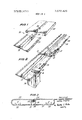
- FIG. 1 is a perspective view of part of a rail body of a device according to the invention before the upper rail member and the lower rail member thereof are secured together;
- FIG. 2 shows a part of a lower rail member with an electric drive motor, pulley arrangement and switch members
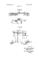
- FIG. 3 is a cross sectional view through a second embodiment of a rail body
- FIG. 4 is an exploded cross sectional view through a third embodiment of a rail body before the upper rail and lower rail thereof are secured together;
- FIG. 5 is a perspective view of an electric drive motor, a relay and a change-over switch
- FIG. 6 is a perspective view of a pulley arrangement
- FIG. 7 is a sectional view through part of a cord tensioning device
- FIGS. 8 to 10 show further embodiments of rail bodies
- FIG. 11 is an exploded perspective view of a cord tensioning device.
- a suspension device 20 comprises a rail body formed by a lower rail member 21 and an upper rail member 22, each formed of metal or plastics materials.
- the lower rail member 21 and the upper rail member 22 are joined by an intermediate member 23 which is accommodated in a channelshaped recess 24 in the lower rail member 21.
- the intermediate member 23 is secured in its operative position by means of screws 25.
- FIG. 2 shows a perspective view of a part of a lower rail member 21 which carries a drive motor 26 at its underside.
- the drive motor is coupled to a gear pulley arrangement 27 secured to the upper face of the lower rail member 21 and is connected by way of draw cords 28 to a cord tensioning device 29.
- draw cords 28 Connected to the draw cords 28 are curtain support means, of which only a draw carriage 30 is shown.
- the lower rail member 21 and the upper rail member 22 together form two pairs of parallel guide tracks 31 for the rolling or sliding draw carriages 30.
- the guide tracks 31 are formed by flange portions, the edges of which flange portions are rounded and curved slightly upwardly, thereby defining a guide slot 32.
- the lower rail member 21 and the upper rail member 22 are secured together by screws engaging tapped holes in the transverse web 34.
- FIG. 4 is of substantially the same construction as the rail body shown in FIGS. 1, 2 and 3. In this case, however, the screws 25 cooperate with a screwhead 35 accommodated in the space 24.
- the gear pulley arrangement 27 and the cord tensioning means 29 are secured in the interior of the upper rail member 22, by means of rivets. As shown in FIG. 4, both the gear pulley arrangement 27 and also the cord tensioning means 29 are completely enclosed by the walls of the rail body.
- FIG. 5 shows the drive motor 26 and a relay 36 which are secured to a common mounting plate 37.
- the mounting plate 37 can be secured to the underside of the lower rail member 21 by means of screws, in like manner to that shown in FIG. 4.
- the drive motor 26 is connected by way of electrical supply leads 38 to a power supply plug 39 and to a change-over switch 40.
- the change-over switch 40 has three juxtaposed switch members 41, 42 and 43.
- the switch member 41 In order to pen curtains carried by the curtain support means, the switch member 41 is moved into its operative position by being pressed in, the drive motor 26 is thus set in operation and the curtains are moved into an open position by means of the draw cords 28.
- the switch member 41 is moved back into its starting position by actuating the switch member 42.
- the switch member 43 When the switch member 43 is pressed in, the rotor of the drive motor 26 rotates in the reverse direction, thus closing the curtains.
- the gear pulley arrangement 27 comprises a gear heel 44 which is connected to a motor shaft 45 and which drives a gear wheel 46 coupled to a cord pulley 47.
- the cord pulley 47 is connected to the cord tensioning means by way of the draw cord 28 which is endless.
- micro-switches 48 which, as shown in FIG. 2, are secured, at desired limit positions, to the lower rail member 21. Switching is effected by means of trip members 62 arranged on the draw carriage 30.
- FIG. 6 shows a second embodiment of the gear pulley arrangement 27, in which the gear pulley arrangement 27 comprises simple cord pulleys 49 of which the larger is coupled to the drive shaft 45.
- the drive cord pulley is shown in cross-section in FIG. 7. It comprises an inner plastics body 50 and two external discs 51 and 52.
- the plastics body 50 comprises a wear-resistant resilient plastics material, for example ethylene glycol-adipic acid polyester. When obstructions occur which prevent closing or opening movement of the curtains, the surface of this plastics material no longer entrains the draw cords 28 so that the motor 26 runs idle and damage to the device is avoided.
- FIG. 8 shows another possible form of a rail body.
- the upper rail member 22 carries holding claws 53 which cooperate with corresponding holding members 54 carried on the spacer members 33. With this construction, it is not possible to release the lower rail member 21 from the upper rail member 22 after they have been secured together.
- the upper rail member 22 and the lower rail member 21 are secured together by means of a U-shape intermediate member 55 which is fixedly connected at its upper end to the upper rail member 22 and which has on its free limbs 56 holding claws which cooperate with correspondingly formed members on the lower rail member 21.
- FIG. shows a further embodiment of a rail body.
- the spacer members 33 are joined together by an intermediate web portion 34.
- the upper rail member 22 is in two parts which are secured to the transverse web portion 34 by means of screws 25.
- FIG. 11 shows a perspective view of the cord tensioning device 29.
- the cord tensioning device 29 comprises a U-shape frame 57 which can be inserted into the rail body and secured by a clamping screw 58 which is provided with a wide collar 59. After releasing the clamping screw 58, the cord tensioning means 29 can be displaced in the guide slot 32.
- the cord pulley 49 of the cord tensioning means 29 has a spindle 60 which is extended downwardly and forms a handle member 61.
- a curtain suspension device comprising, in combination, an upper rail member; a lower rail member; means connecting said rail members in superimposed position; draw cords for effecting opening and closing curtains supported on said device; guide means for guiding said draw cords and including at least one drive pulley; motor means; and transmission means between said motor means and said drive pulley, said guide means and said transmission means being mounted on said upper rail member and said motor means being mounted on said lower rail member to facilitate assembly of the device.
- one of said rail members has a width smaller than the other rail member and wherein the other of the rail members curves at opposite sides toward opposite longitudinal edges of said one rail member so as to form with the latter a substantially closed hollow body.
- said motor means comprise an electromotor and a relay, and including a common mounting plate mounting said motor and said relay and being releasably connected to said lower rail member.
- said guide means comprise tensioning means for maintaining said cords in taut condition.
- said guide means comprise tensioning means for maintaining said cords in taut condition, said tensioning means comprising a frame adjustably mounted in the space between said rail members.
- tensioning means comprise a guide pulley mounted on a spindle carried by said frame, said spindle having an end portion projecting beyond said lower rail for facilitating positioning of said guide pulley relative to said drive pulley.
Landscapes
- Curtains And Furnishings For Windows Or Doors (AREA)
Applications Claiming Priority (1)
| Application Number | Priority Date | Filing Date | Title |
|---|---|---|---|
| DE19691936521 DE1936521C3 (de) | 1969-07-18 | Vorhangaufhängevorrichtung mit motorischem, insbesondere elektromotorischem Antrieb |
Publications (1)
| Publication Number | Publication Date |
|---|---|
| US3672425A true US3672425A (en) | 1972-06-27 |
Family
ID=5740160
Family Applications (1)
| Application Number | Title | Priority Date | Filing Date |
|---|---|---|---|
| US55353A Expired - Lifetime US3672425A (en) | 1969-07-18 | 1970-07-16 | Curtain suspension devices with an electric motor drive |
Country Status (9)
| Country | Link |
|---|---|
| US (1) | US3672425A (fr) |
| BE (1) | BE753226A (fr) |
| BR (1) | BR6912395D0 (fr) |
| CA (1) | CA918559A (fr) |
| FR (1) | FR2054309A5 (fr) |
| GB (1) | GB1260773A (fr) |
| NL (1) | NL7010557A (fr) |
| SE (1) | SE366640B (fr) |
| ZA (1) | ZA704867B (fr) |
Cited By (8)
| Publication number | Priority date | Publication date | Assignee | Title |
|---|---|---|---|---|
| US4546809A (en) * | 1983-11-25 | 1985-10-15 | Hadfield Elden E | Dual track drapery support device |
| US4683933A (en) * | 1984-07-16 | 1987-08-04 | Inside Outfitters, Inc. | Motor driven shade lowering and raising mechanism for atrium walls |
| US4770224A (en) * | 1986-06-18 | 1988-09-13 | Kelley Company, Inc. | Power operated industrial door |
| US4819708A (en) * | 1987-03-17 | 1989-04-11 | Toso Kabushiki Kaisha (Toso Company Limited) | Manually operable electric curtain |
| US4827199A (en) * | 1988-03-15 | 1989-05-02 | Graber Industries, Inc. | Torque responsive motor-drive assembly |
| US4874026A (en) * | 1988-04-04 | 1989-10-17 | Dayer Worrall | Vehicle window screen assembly |
| US20040026049A1 (en) * | 2000-12-28 | 2004-02-12 | Park Won-Seo | Assembly power curtain |
| US20070277935A1 (en) * | 2006-06-01 | 2007-12-06 | Shih-Ming Lin | Curtain |
Families Citing this family (1)
| Publication number | Priority date | Publication date | Assignee | Title |
|---|---|---|---|---|
| CN115211711B (zh) * | 2022-05-27 | 2024-09-10 | 杭州威仕达机电科技有限公司 | 高集成度双驱动电动窗帘 |
-
1969
- 1969-09-12 BR BR212395/69A patent/BR6912395D0/pt unknown
-
1970
- 1970-07-08 FR FR7025240A patent/FR2054309A5/fr not_active Expired
- 1970-07-09 BE BE753226D patent/BE753226A/fr unknown
- 1970-07-15 SE SE09802/70A patent/SE366640B/xx unknown
- 1970-07-15 ZA ZA704867A patent/ZA704867B/xx unknown
- 1970-07-16 NL NL7010557A patent/NL7010557A/xx unknown
- 1970-07-16 US US55353A patent/US3672425A/en not_active Expired - Lifetime
- 1970-07-17 GB GB34854/70A patent/GB1260773A/en not_active Expired
- 1970-07-17 CA CA088464A patent/CA918559A/en not_active Expired
Cited By (10)
| Publication number | Priority date | Publication date | Assignee | Title |
|---|---|---|---|---|
| US4546809A (en) * | 1983-11-25 | 1985-10-15 | Hadfield Elden E | Dual track drapery support device |
| US4683933A (en) * | 1984-07-16 | 1987-08-04 | Inside Outfitters, Inc. | Motor driven shade lowering and raising mechanism for atrium walls |
| US4770224A (en) * | 1986-06-18 | 1988-09-13 | Kelley Company, Inc. | Power operated industrial door |
| US4819708A (en) * | 1987-03-17 | 1989-04-11 | Toso Kabushiki Kaisha (Toso Company Limited) | Manually operable electric curtain |
| US4827199A (en) * | 1988-03-15 | 1989-05-02 | Graber Industries, Inc. | Torque responsive motor-drive assembly |
| US4874026A (en) * | 1988-04-04 | 1989-10-17 | Dayer Worrall | Vehicle window screen assembly |
| US20040026049A1 (en) * | 2000-12-28 | 2004-02-12 | Park Won-Seo | Assembly power curtain |
| US6827121B2 (en) * | 2000-12-28 | 2004-12-07 | Technogate Co., Ltd. | Assembly power curtain |
| EP1345516A4 (fr) * | 2000-12-28 | 2005-06-01 | Technogate Co Ltd | Ensemble rideau electrique |
| US20070277935A1 (en) * | 2006-06-01 | 2007-12-06 | Shih-Ming Lin | Curtain |
Also Published As
| Publication number | Publication date |
|---|---|
| NL7010557A (fr) | 1971-01-20 |
| DE1936521A1 (de) | 1971-01-28 |
| FR2054309A5 (fr) | 1971-04-16 |
| BE753226A (fr) | 1970-12-16 |
| CA918559A (en) | 1973-01-09 |
| BR6912395D0 (pt) | 1973-02-08 |
| ZA704867B (en) | 1971-04-28 |
| SE366640B (fr) | 1974-05-06 |
| DE1936521B2 (de) | 1977-05-05 |
| GB1260773A (en) | 1972-01-19 |
Similar Documents
| Publication | Publication Date | Title |
|---|---|---|
| US3331428A (en) | Structural device | |
| US3672425A (en) | Curtain suspension devices with an electric motor drive | |
| US6112462A (en) | Single-drum dual-cable window regulator | |
| JPS59181157A (ja) | マツサ−ジ装置 | |
| US3835980A (en) | Conveyor with extendible booms | |
| CN112338981B (zh) | 一种光缆光纤加工用切断设备 | |
| US4754572A (en) | Motor-operated sliding door assembly | |
| CA2099088A1 (fr) | Interrupteur de fin de course pour ouvre-porte de garage | |
| US20090008046A1 (en) | Device for Operating a Screen, Such as a Window Covering | |
| DE69119379D1 (de) | Antriebsrad für Fahrzeuge mit elektrischem Antrieb | |
| AU7764100A (en) | Shutter with articulated elements equipped with an electrical driving device | |
| FR2416809A1 (fr) | Portiere de vehicule automobile | |
| US4184570A (en) | Wall-mounted fork lift | |
| DE3481037D1 (de) | Ferngesteuertes spielzeugauto mit windwerk. | |
| DE59401014D1 (de) | Transporteinheit einer Flurtransportanlage | |
| CN109973002A (zh) | 一种中空百叶玻璃窗的升降定位机构 | |
| EP0520475B1 (fr) | Motoréducteur pour véhicule autoroulant | |
| JPS6217068Y2 (fr) | ||
| CN222853603U (zh) | 一种窗帘助推装置 | |
| US3541971A (en) | Tray crawler | |
| CN223991684U (zh) | 一种汽车车窗升降器 | |
| CN219176168U (zh) | 稳定型自动门 | |
| CN213282503U (zh) | 一种耐久抗老性能好的窗帘电机 | |
| CN217972125U (zh) | 一种双轨双通道转轨器 | |
| US1903691A (en) | Ironing machine |