US3680809A - Reel - Google Patents
Reel Download PDFInfo
- Publication number
- US3680809A US3680809A US660A US3680809DA US3680809A US 3680809 A US3680809 A US 3680809A US 660 A US660 A US 660A US 3680809D A US3680809D A US 3680809DA US 3680809 A US3680809 A US 3680809A
- Authority
- US
- United States
- Prior art keywords
- fittings
- barrel
- head
- reel
- disc
- Prior art date
- Legal status (The legal status is an assumption and is not a legal conclusion. Google has not performed a legal analysis and makes no representation as to the accuracy of the status listed.)
- Expired - Lifetime
Links
Images

Classifications
-
- B—PERFORMING OPERATIONS; TRANSPORTING
- B21—MECHANICAL METAL-WORKING WITHOUT ESSENTIALLY REMOVING MATERIAL; PUNCHING METAL
- B21C—MANUFACTURE OF METAL SHEETS, WIRE, RODS, TUBES, PROFILES OR LIKE SEMI-MANUFACTURED PRODUCTS OTHERWISE THAN BY ROLLING; AUXILIARY OPERATIONS USED IN CONNECTION WITH METAL-WORKING WITHOUT ESSENTIALLY REMOVING MATERIAL
- B21C47/00—Winding-up, coiling or winding-off metal wire, metal band or other flexible metal material characterised by features relevant to metal processing only
- B21C47/28—Drums or other coil-holders
-
- B—PERFORMING OPERATIONS; TRANSPORTING
- B65—CONVEYING; PACKING; STORING; HANDLING THIN OR FILAMENTARY MATERIAL
- B65H—HANDLING THIN OR FILAMENTARY MATERIAL, e.g. SHEETS, WEBS, CABLES
- B65H75/00—Storing webs, tapes, or filamentary material, e.g. on reels
- B65H75/02—Cores, formers, supports, or holders for coiled, wound, or folded material, e.g. reels, spindles, bobbins, cop tubes, cans, mandrels or chucks
- B65H75/04—Kinds or types
- B65H75/08—Kinds or types of circular or polygonal cross-section
- B65H75/14—Kinds or types of circular or polygonal cross-section with two end flanges
-
- B—PERFORMING OPERATIONS; TRANSPORTING
- B65—CONVEYING; PACKING; STORING; HANDLING THIN OR FILAMENTARY MATERIAL
- B65H—HANDLING THIN OR FILAMENTARY MATERIAL, e.g. SHEETS, WEBS, CABLES
- B65H2701/00—Handled material; Storage means
- B65H2701/30—Handled filamentary material
- B65H2701/31—Textiles threads or artificial strands of filaments
-
- B—PERFORMING OPERATIONS; TRANSPORTING
- B65—CONVEYING; PACKING; STORING; HANDLING THIN OR FILAMENTARY MATERIAL
- B65H—HANDLING THIN OR FILAMENTARY MATERIAL, e.g. SHEETS, WEBS, CABLES
- B65H2701/00—Handled material; Storage means
- B65H2701/50—Storage means for webs, tapes, or filamentary material
- B65H2701/51—Cores or reels characterised by the material
- B65H2701/512—Cores or reels characterised by the material moulded
- B65H2701/5122—Plastics
-
- B—PERFORMING OPERATIONS; TRANSPORTING
- B65—CONVEYING; PACKING; STORING; HANDLING THIN OR FILAMENTARY MATERIAL
- B65H—HANDLING THIN OR FILAMENTARY MATERIAL, e.g. SHEETS, WEBS, CABLES
- B65H2701/00—Handled material; Storage means
- B65H2701/50—Storage means for webs, tapes, or filamentary material
- B65H2701/51—Cores or reels characterised by the material
- B65H2701/513—Cores or reels characterised by the material assembled mainly from rigid elements of the same kind
- B65H2701/5136—Moulded plastic elements
Definitions
- the reelof the present invention makes use of a uniquely designed head to further ease the problem of stocking unassembled reels.
- the head is designed with intermeshing fittings on both its sides.
- the fittings on one side being so positioned as to intermesh with a barrel of one diameter and the fittings on the other side so positioned as to intermesh with a barrel of another diameter.
- barrels of different lengths may be used to add another degree of versatility to the standardized head design.
- These drums have spaced slots along the periphery of each end which matewith the fittings on the heads.
- the nature of the intermeshing fittings is such that there is a built in torque resistance as between the barrel and heads.
- the components When placed in intermeshing position the components may be permanently secured by bonding or welding or the components may be detachably secured by hardware such that they may be disassembled after use.
- the faces of the heads are so designed with an alternating ribbing that there are no annular grooves or ridges on the faces which would trap or snag the wire or other strand material while it is being wound or unwound.
- the result is one flush face height extending across each of the faces of the head.
- An addedbenefit of this alternating ribbing is the greater strength given to the heads.
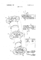
- FIG. 1 is a detached perspective view showing the versatility of the components by illustrating how the two different diameter barrels may be used in conjunction with a single head design;
- FIG. 2 is an end elevational view of one of the heads with the connecting hardware removed for clarity;
- FIG. 3 is a front elevational view illustrating one of the heads in section as taken along line 3-3 of FIG. 2 and showing the use of the smaller diameter barrel;
- FIG. 4 is a front elevational view illustrating one of the heads in section as taken along line 4-4 of FIG. 2 and showing the use of the larger diameter barrel;
- FIG. 5 is an enlarged sectional detail view taken along line 5-5 of FIG. 2 with the attaching hardware added to the view;
- FIG. 6 is an enlarged sectional detail view taken along line 6-6 of FIG. 2 with the attaching hardware added to the view;
- FIG. 7 is an enlarged sectional detail view of the mating portions of the smaller diameter barrel and one of the heads.
- the numeral 10 designates a uniquely designed head for a reel.
- the perspective view depicts how the same head 10 can be assemble with barrels of differing diameters.
- the barrel 12 might have a diameter of 10 inches and barrel 50 a diameter of 14 inches. It is to be realized that an assembled reel would look like the ones shown in FIGS. 3 or 4.
- FIGS. 2, 3 and 4 The structure of the head is best described by reference to FIGS. 2, 3 and 4.
- a hub 14 having inner annular shoulders 16 and 18 into which an optional center tube 20 may be inserted.
- the shoulders are on opposite sides of the hub such that the optional center tube can be used when using either the larger or smaller diameter barrel.
- the surface on one side of the head is flat and forms two sub stantially half moon portions 24 with axial drive slots 26 therebetween and on opposing sides of the hub.
- Ribs 28 connect the hub 14 to annular rib 30.
- spoke ribs 32 Extending outwardly from annular rib 30 are spoke ribs 32 connected to a second annular rib 34 and which are used to reinforce annular web 36.
- annular band Formed outwardly from the second annular rib 34 is an annular band consisting of alternatingly raised rib panels 38 and recessed rib panels 40.
- the circular heads may be formed from a suitable synthetic resin or other suitable plastic, as for instance foamed polystyrene or urethane.
- rib members act as the intermeshing fittings depending upon the diameter of the barrel used.
- the slots 42 as shown in FIG. 7 slide over ribs 28 to form a torque resistant connection.
- the slots 52 slip over spoke ribs 32 on the other side of the head to form an intermeshing fitting.
- FIGS. 5 and 6 illustrate the use of bolts and nuts to assemble the reels. As seen in FIG. 5 bolts threaded on both ends would extend through the inside of the barrel 50 and emerge through holes 44 in the heads where washers and nuts would be tightened in the recesses 45.
- a reel for winding wire or other stranded material comprising a pair of identically formed reel heads, a cylindrically shaped barrel having a plurality of intermeshing fittings along the outer periphery of each of its ends, said heads each having a plurality of first fittings on one of their sides positioned and formed in such a configuration as to intermeshingly mate with the plurality of fittings along the periphery of each end of said barrel, the other sides of said heads having a plurality of intermeshing second fittings placed at a second radial distance from the center of the head different from the radial distance of the first fittings on the reverse side of the head such that the second fittings can be used to connect a barrel of a second diameter therebetween, the second barrel having fittings to intermeshingly connect with said second fittings on said heads to form a reel having a different load capacity, said fittings on both sides of the heads being radial ribs that intermesh with mating slots along the peripheral ends of an intermediately positioned barrel.
- a reel head for use in combination with an identical head, each head to be attached to the opposite ends of a barrel, said reel head comprising a disc having a center hole, said disc having a plurality of first fittings on one side positioned and formed in such a configuration as to intermeshingly mate with a plurality of fittings along the periphery of the end of a barrel, the other side of said disc having a plurality of intermeshing second fittings placed at a second radial distance from the center of the disc different from the radial distance of the first fittings on the reverse side of the disc such that the second fittings may be used to connect a different barrel of a second diameter thereto, the different barrel having fittings to intermeshingly connect with said second fittings, said fittings on both sides of the discs being radial ribs that would intermesh with mating slots along the peripheral end of a barrel.
- a reel for winding wire or other stranded material comprising a pair of identically formed reel head members, a cylindrically shaped barrel member having a plurality of fittings along the outer periphery of each of its ends, said head members each having a plurality of first fittings on one of their sides positioned and formed in such a configuration as to intermeshingly mate with the plurality of fittings along the periphery of each end of said barrel member, the other sides of said heads having a plurality of intermeshing second fittings placed at a second radial distance from the center of the head different from the radial distance of the first fittings and on the reverse side of the head member such that the second fittings can be used to connect a barrel memb r of a second, dia eter therebetween, t e secon barre member having ittings to intermeshing y connect with said second fittings on said head member to form a reel having a different load capacity, said fittings on the barrel member and fittings on said head member comprising integral
- a reel head for use in combination with an identical head, each head to be attached to the opposite ends of a barrel, said reel head comprising a disc having a center hole, said disc having a plurality of first fittings on one side positioned and formed in such a configuration as to intermeshingly mate with a plurality of fittings along the periphery of the end of a barrel, the other side of said.
- the disc having a plurality of intermeshing second fittings placed at a second radial distance from the center of the disc different from the radial distance of the first fittings and on the reverse side of the disc such that the second fittings may be used to connect a different barrel of a second diameter thereto, the different barrel having fittings to intermeshingly connect with said second fittings, said fittings on said disc comprising integral fixed projections to enter recesses on the barrel ends.
Landscapes
- Engineering & Computer Science (AREA)
- Mechanical Engineering (AREA)
- Storage Of Web-Like Or Filamentary Materials (AREA)
Abstract
A wire reel having identical molded heads with intermeshing fittings formed on opposite sides of the heads, said fittings being positioned with respect to the center of the heads so that the fittings on one side intermesh with a barrel of one diameter and the fittings on the other side intermesh with a barrel of another diameter.
Description
United States Patent 118,61,242/l18.62,118.4,ll8.41,118,115, 77, 77.3, 77.4, 71.8, 73, 71.9, 110, 110.1
Blackmer et al. [4 Aug. 1, 1972 I541 REEL Q1 61 i V 1 fldk i ii Cit i. 8 [72] Inventors: Dwight W. Blackmer, Cumberland; UNITED STATES PATENTS Robert N. Bernie W k t, both of 6 3,160,362 12/1964 Weber ..242/110x 2,494,521 1 1950 h f ta]. ..242 118.8 [73] Assignee: Wanskuck Company P E l G Sc l I rimary xaminer eorge autz [22] Ffled' 1970 Attorney-Barlow and Barlow [21] Appi. No.: 660 [57] ABSTRACT 521 US. Cl. ..242/118.6 242/73 242/773 A Wire having identical mlded heads with inter 2,42 kn/118.7 meshing fittings formed on opposite sides of the heads, 51 1111. c1. ..B65h 75/14 said fittings being positioned with respect to the center [58] Field of Search ..242/1181. 9f he he ggisgo that the fittipgson one side intermesh with a barrel of one diameter and the'fittings on the other side intermesh with a barrel of another diameter.
4 Claims, 7 Drawing Figures PATENTEUAUE 1 I972 SHEET 1 [IF 2 ATTORNEYS REEL BACKGROUND OF THE INVENTION The invention relates to reels for receiving wire and other material in strip or strand form. These'reels also provide a shipping package for transporting their contents from one place to another.
In the past one of the problems confronting industry involved in winding wire or other strand material has been the number of different sized reels that had to be inventoried for winding different lengths or sizes of wire. Reels in the assembled ready to use state require bulkier packages resulting in increased shipping charges to the wire manufacturer. Also once the wire manufacturer receives the reels, the storing problem is compounded by all the different sizes of reels to be inventoried. A step in the right direction has been the shipping and storage of reels in a disassembled state with the reels being assembled as needed. This has reduced shipping charges. However, further savings in this, area will: be mostly confined to making the components of lighter materials of sufficient strength. Although this advance has been considerable and the amount of storage area required greatly reduced, a large area'is still required tohouse the reel components andthe wire winding industry has patiently awaited a solution to this problem.
SUMMARY OF THE INVENTION The reelof the present invention makes use of a uniquely designed head to further ease the problem of stocking unassembled reels. The head is designed with intermeshing fittings on both its sides. The fittings on one side being so positioned as to intermesh with a barrel of one diameter and the fittings on the other side so positioned as to intermesh with a barrel of another diameter. This interchangeability reduces the number of different heads to bestocked by one half, reduces the amount of space necessary to store the reel components, and results in less money being tied up in reel components.
In assembling the reels,,barrels of different lengths may be used to add another degree of versatility to the standardized head design. These drums have spaced slots along the periphery of each end which matewith the fittings on the heads. The nature of the intermeshing fittings is such that there is a built in torque resistance as between the barrel and heads. When placed in intermeshing position the components may be permanently secured by bonding or welding or the components may be detachably secured by hardware such that they may be disassembled after use.
The faces of the heads are so designed with an alternating ribbing that there are no annular grooves or ridges on the faces which would trap or snag the wire or other strand material while it is being wound or unwound. The result is one flush face height extending across each of the faces of the head. An addedbenefit of this alternating ribbing is the greater strength given to the heads.
DESCRIPTION OF THE DRAWINGS FIG. 1 is a detached perspective view showing the versatility of the components by illustrating how the two different diameter barrels may be used in conjunction with a single head design;
FIG. 2 is an end elevational view of one of the heads with the connecting hardware removed for clarity;
FIG. 3 is a front elevational view illustrating one of the heads in section as taken along line 3-3 of FIG. 2 and showing the use of the smaller diameter barrel;
FIG. 4 is a front elevational view illustrating one of the heads in section as taken along line 4-4 of FIG. 2 and showing the use of the larger diameter barrel;
FIG. 5 is an enlarged sectional detail view taken along line 5-5 of FIG. 2 with the attaching hardware added to the view;
FIG. 6 is an enlarged sectional detail view taken along line 6-6 of FIG. 2 with the attaching hardware added to the view; and
FIG. 7 is an enlarged sectional detail view of the mating portions of the smaller diameter barrel and one of the heads.
DESCRIPTION OF THE PREFERRED EMBODIMENT Referring to FIG. 1, the numeral 10 designates a uniquely designed head for a reel. The perspective view depicts how the same head 10 can be assemble with barrels of differing diameters. For example, the barrel 12 might have a diameter of 10 inches and barrel 50 a diameter of 14 inches. It is to be realized that an assembled reel would look like the ones shown in FIGS. 3 or 4.
The structure of the head is best described by reference to FIGS. 2, 3 and 4. At the center of the head is a hub 14 having inner annular shoulders 16 and 18 into which an optional center tube 20 may be inserted. The shoulders are on opposite sides of the hub such that the optional center tube can be used when using either the larger or smaller diameter barrel. Extending outwardly from the center hole 22 in the hub, the surface on one side of the head is flat and forms two sub stantially half moon portions 24 with axial drive slots 26 therebetween and on opposing sides of the hub. Ribs 28 connect the hub 14 to annular rib 30. Extending outwardly from annular rib 30 are spoke ribs 32 connected to a second annular rib 34 and which are used to reinforce annular web 36. Formed outwardly from the second annular rib 34 is an annular band consisting of alternatingly raised rib panels 38 and recessed rib panels 40. The circular heads may be formed from a suitable synthetic resin or other suitable plastic, as for instance foamed polystyrene or urethane.
When assembling a reel, different rib members act as the intermeshing fittings depending upon the diameter of the barrel used. For instance when using barrel 12, the slots 42 as shown in FIG. 7 slide over ribs 28 to form a torque resistant connection. When using a larger diameter barrel such as 50, the slots 52 slip over spoke ribs 32 on the other side of the head to form an intermeshing fitting. With the barrel and heads connected together, they may be secured by welding, bonding, or attached together with hardware. An advantage of using hardware is the fact that the reels may be easily disassembled after use for storage, return shipping, etc.
FIGS. 5 and 6 illustrate the use of bolts and nuts to assemble the reels. As seen in FIG. 5 bolts threaded on both ends would extend through the inside of the barrel 50 and emerge through holes 44 in the heads where washers and nuts would be tightened in the recesses 45.
Similarly in FIG. 6, bolts would be inserted through holes 48 of the recesses 49 when barrel 12 is being used.
It is to be understood that the above embodiments are illustrative of the invention and are by no means restrictive thereof. It is reasonably to be expected that persons skilled in the art can make numerous revisions and adaptations of the invention to suit individual design preferences, and it is intended that such revisions and adaptations which incorporate the herein disclosed principles will be included within the scope of the following claims as equivalents of the invention.
We claim:
1. A reel for winding wire or other stranded material comprising a pair of identically formed reel heads, a cylindrically shaped barrel having a plurality of intermeshing fittings along the outer periphery of each of its ends, said heads each having a plurality of first fittings on one of their sides positioned and formed in such a configuration as to intermeshingly mate with the plurality of fittings along the periphery of each end of said barrel, the other sides of said heads having a plurality of intermeshing second fittings placed at a second radial distance from the center of the head different from the radial distance of the first fittings on the reverse side of the head such that the second fittings can be used to connect a barrel of a second diameter therebetween, the second barrel having fittings to intermeshingly connect with said second fittings on said heads to form a reel having a different load capacity, said fittings on both sides of the heads being radial ribs that intermesh with mating slots along the peripheral ends of an intermediately positioned barrel.
2. A reel head for use in combination with an identical head, each head to be attached to the opposite ends of a barrel, said reel head comprising a disc having a center hole, said disc having a plurality of first fittings on one side positioned and formed in such a configuration as to intermeshingly mate with a plurality of fittings along the periphery of the end of a barrel, the other side of said disc having a plurality of intermeshing second fittings placed at a second radial distance from the center of the disc different from the radial distance of the first fittings on the reverse side of the disc such that the second fittings may be used to connect a different barrel of a second diameter thereto, the different barrel having fittings to intermeshingly connect with said second fittings, said fittings on both sides of the discs being radial ribs that would intermesh with mating slots along the peripheral end of a barrel.
3. A reel for winding wire or other stranded material comprising a pair of identically formed reel head members, a cylindrically shaped barrel member having a plurality of fittings along the outer periphery of each of its ends, said head members each having a plurality of first fittings on one of their sides positioned and formed in such a configuration as to intermeshingly mate with the plurality of fittings along the periphery of each end of said barrel member, the other sides of said heads having a plurality of intermeshing second fittings placed at a second radial distance from the center of the head different from the radial distance of the first fittings and on the reverse side of the head member such that the second fittings can be used to connect a barrel memb r of a second, dia eter therebetween, t e secon barre member having ittings to intermeshing y connect with said second fittings on said head member to form a reel having a different load capacity, said fittings on the barrel member and fittings on said head member comprising integral fixed projections on said head member and recesses on the barrel member to interfit with each other.
4. A reel head for use in combination with an identical head, each head to be attached to the opposite ends of a barrel, said reel head comprising a disc having a center hole, said disc having a plurality of first fittings on one side positioned and formed in such a configuration as to intermeshingly mate with a plurality of fittings along the periphery of the end of a barrel, the other side of said. disc having a plurality of intermeshing second fittings placed at a second radial distance from the center of the disc different from the radial distance of the first fittings and on the reverse side of the disc such that the second fittings may be used to connect a different barrel of a second diameter thereto, the different barrel having fittings to intermeshingly connect with said second fittings, said fittings on said disc comprising integral fixed projections to enter recesses on the barrel ends.
Claims (4)
1. A reel for winding wire or other stranded material comprising a pair of identically formed reel heads, a cylindrically shapEd barrel having a plurality of intermeshing fittings along the outer periphery of each of its ends, said heads each having a plurality of first fittings on one of their sides positioned and formed in such a configuration as to intermeshingly mate with the plurality of fittings along the periphery of each end of said barrel, the other sides of said heads having a plurality of intermeshing second fittings placed at a second radial distance from the center of the head different from the radial distance of the first fittings on the reverse side of the head such that the second fittings can be used to connect a barrel of a second diameter therebetween, the second barrel having fittings to intermeshingly connect with said second fittings on said heads to form a reel having a different load capacity, said fittings on both sides of the heads being radial ribs that intermesh with mating slots along the peripheral ends of an intermediately positioned barrel.
2. A reel head for use in combination with an identical head, each head to be attached to the opposite ends of a barrel, said reel head comprising a disc having a center hole, said disc having a plurality of first fittings on one side positioned and formed in such a configuration as to intermeshingly mate with a plurality of fittings along the periphery of the end of a barrel, the other side of said disc having a plurality of intermeshing second fittings placed at a second radial distance from the center of the disc different from the radial distance of the first fittings on the reverse side of the disc such that the second fittings may be used to connect a different barrel of a second diameter thereto, the different barrel having fittings to intermeshingly connect with said second fittings, said fittings on both sides of the discs being radial ribs that would intermesh with mating slots along the peripheral end of a barrel.
3. A reel for winding wire or other stranded material comprising a pair of identically formed reel head members, a cylindrically shaped barrel member having a plurality of fittings along the outer periphery of each of its ends, said head members each having a plurality of first fittings on one of their sides positioned and formed in such a configuration as to intermeshingly mate with the plurality of fittings along the periphery of each end of said barrel member, the other sides of said heads having a plurality of intermeshing second fittings placed at a second radial distance from the center of the head different from the radial distance of the first fittings and on the reverse side of the head member such that the second fittings can be used to connect a barrel member of a second diameter therebetween, the second barrel member having fittings to intermeshingly connect with said second fittings on said head member to form a reel having a different load capacity, said fittings on the barrel member and fittings on said head member comprising integral fixed projections on said head member and recesses on the barrel member to interfit with each other.
4. A reel head for use in combination with an identical head, each head to be attached to the opposite ends of a barrel, said reel head comprising a disc having a center hole, said disc having a plurality of first fittings on one side positioned and formed in such a configuration as to intermeshingly mate with a plurality of fittings along the periphery of the end of a barrel, the other side of said disc having a plurality of intermeshing second fittings placed at a second radial distance from the center of the disc different from the radial distance of the first fittings and on the reverse side of the disc such that the second fittings may be used to connect a different barrel of a second diameter thereto, the different barrel having fittings to intermeshingly connect with said second fittings, said fittings on said disc comprising integral fixed projections to enter recesses on the barrel ends.
Applications Claiming Priority (1)
| Application Number | Priority Date | Filing Date | Title |
|---|---|---|---|
| US66070A | 1970-01-05 | 1970-01-05 |
Publications (1)
| Publication Number | Publication Date |
|---|---|
| US3680809A true US3680809A (en) | 1972-08-01 |
Family
ID=21692479
Family Applications (1)
| Application Number | Title | Priority Date | Filing Date |
|---|---|---|---|
| US660A Expired - Lifetime US3680809A (en) | 1970-01-05 | 1970-01-05 | Reel |
Country Status (1)
| Country | Link |
|---|---|
| US (1) | US3680809A (en) |
Cited By (11)
| Publication number | Priority date | Publication date | Assignee | Title |
|---|---|---|---|---|
| GB2162493A (en) * | 1984-08-03 | 1986-02-05 | Peter John Drennan | Fishing line spools |
| USD301834S (en) | 1986-04-11 | 1989-06-27 | Soltes Isaac B | Cord retaining reel or similar article |
| GB2263099A (en) * | 1992-01-10 | 1993-07-14 | Young & Company Cases Limited | Securing spool flanges to spool core |
| USD341770S (en) | 1992-06-02 | 1993-11-30 | O. Ames Co. | Wall supported hose reel |
| US6179104B1 (en) * | 1998-06-16 | 2001-01-30 | Atlanta Kabel Steinmuller Gmbh + Co. Kg | Self-winding cable reel |
| US20060086863A1 (en) * | 2004-10-22 | 2006-04-27 | Couchey Brian P | Shipping spool |
| US20090152390A1 (en) * | 2007-12-14 | 2009-06-18 | The Boeing Company | Cable despooling and spooling |
| US8272591B2 (en) | 2011-01-24 | 2012-09-25 | Sonoco, Inc. | Breakdown spool |
| EP2794447A4 (en) * | 2011-12-22 | 2015-08-12 | Foretrek Systems Pty Ltd | Sleeve for a cable spool |
| USD948994S1 (en) * | 2019-09-24 | 2022-04-19 | Ralph Mugerdichian | Construction line reel |
| US11530109B2 (en) | 2018-03-29 | 2022-12-20 | Commscope Technologies Llc | Collapsible, re-useable spool |
Citations (2)
| Publication number | Priority date | Publication date | Assignee | Title |
|---|---|---|---|---|
| US2494521A (en) * | 1945-09-15 | 1950-01-10 | Republic Steel Corp | Cable reel |
| US3160362A (en) * | 1962-08-08 | 1964-12-08 | Gleason Reel Corp | Adjustable drum for automatic take-up reel |
-
1970
- 1970-01-05 US US660A patent/US3680809A/en not_active Expired - Lifetime
Patent Citations (2)
| Publication number | Priority date | Publication date | Assignee | Title |
|---|---|---|---|---|
| US2494521A (en) * | 1945-09-15 | 1950-01-10 | Republic Steel Corp | Cable reel |
| US3160362A (en) * | 1962-08-08 | 1964-12-08 | Gleason Reel Corp | Adjustable drum for automatic take-up reel |
Cited By (15)
| Publication number | Priority date | Publication date | Assignee | Title |
|---|---|---|---|---|
| GB2162493A (en) * | 1984-08-03 | 1986-02-05 | Peter John Drennan | Fishing line spools |
| USD301834S (en) | 1986-04-11 | 1989-06-27 | Soltes Isaac B | Cord retaining reel or similar article |
| GB2263099A (en) * | 1992-01-10 | 1993-07-14 | Young & Company Cases Limited | Securing spool flanges to spool core |
| GB2263099B (en) * | 1992-01-10 | 1995-06-14 | Young & Company Cases Limited | Spool |
| USD341770S (en) | 1992-06-02 | 1993-11-30 | O. Ames Co. | Wall supported hose reel |
| US6179104B1 (en) * | 1998-06-16 | 2001-01-30 | Atlanta Kabel Steinmuller Gmbh + Co. Kg | Self-winding cable reel |
| US20060086863A1 (en) * | 2004-10-22 | 2006-04-27 | Couchey Brian P | Shipping spool |
| US7222818B2 (en) | 2004-10-22 | 2007-05-29 | Sonoco Development, Inc. | Shipping spool |
| US20090152390A1 (en) * | 2007-12-14 | 2009-06-18 | The Boeing Company | Cable despooling and spooling |
| US8727262B2 (en) * | 2007-12-14 | 2014-05-20 | The Boeing Company | Cable despooling and spooling |
| US8272591B2 (en) | 2011-01-24 | 2012-09-25 | Sonoco, Inc. | Breakdown spool |
| EP2794447A4 (en) * | 2011-12-22 | 2015-08-12 | Foretrek Systems Pty Ltd | Sleeve for a cable spool |
| US9669990B2 (en) | 2011-12-22 | 2017-06-06 | Foretrek Systems Pty Ltd | Sleeve for a cable spool |
| US11530109B2 (en) | 2018-03-29 | 2022-12-20 | Commscope Technologies Llc | Collapsible, re-useable spool |
| USD948994S1 (en) * | 2019-09-24 | 2022-04-19 | Ralph Mugerdichian | Construction line reel |
Similar Documents
| Publication | Publication Date | Title |
|---|---|---|
| US3680809A (en) | Reel | |
| US4345724A (en) | Lightweight reel | |
| US3565363A (en) | Takedown reel | |
| US3334841A (en) | Plastic spool of complementary halves | |
| US3876073A (en) | Heavy duty paper board reel | |
| US20100025521A1 (en) | Reusable take-apart spool and methods | |
| US3661341A (en) | Collapsible reel | |
| US3150769A (en) | Wire packaging and handling device | |
| US3822841A (en) | Knockdown reel | |
| US3830445A (en) | Reel with spring thread | |
| JPH01294457A (en) | End wall made of moldable material for roll | |
| MX2012004991A (en) | Modular reel structure. | |
| US3235203A (en) | Collapsible reel | |
| US4976475A (en) | Knock down spool | |
| WO2002008107A1 (en) | Collapsible reel assembly | |
| DE4038011C2 (en) | ||
| US2881985A (en) | Reel for receiving a spool of film | |
| US4702429A (en) | Expandable reel assembly | |
| US5203516A (en) | Heavy duty spool | |
| US3743209A (en) | Knockdown reel | |
| US3278135A (en) | Reel construction | |
| US3780964A (en) | Dispenser housing for wire and the like | |
| US20100252672A1 (en) | Spool with drive feature | |
| PL238904B1 (en) | Cable drum and method for assembling thereof | |
| US8267346B2 (en) | Spool assembly with a sealing barrel |