US3689367A - Air-cooled condenser for head fractions in rectifying or distilling columns - Google Patents
Air-cooled condenser for head fractions in rectifying or distilling columns Download PDFInfo
- Publication number
- US3689367A US3689367A US59632A US3689367DA US3689367A US 3689367 A US3689367 A US 3689367A US 59632 A US59632 A US 59632A US 3689367D A US3689367D A US 3689367DA US 3689367 A US3689367 A US 3689367A
- Authority
- US
- United States
- Prior art keywords
- pipes
- air
- condenser
- condensing units
- groups
- Prior art date
- Legal status (The legal status is an assumption and is not a legal conclusion. Google has not performed a legal analysis and makes no representation as to the accuracy of the status listed.)
- Expired - Lifetime
Links
- 238000001556 precipitation Methods 0.000 abstract description 5
- 238000009827 uniform distribution Methods 0.000 abstract description 4
- 238000009833 condensation Methods 0.000 description 7
- 230000005494 condensation Effects 0.000 description 7
- 230000000694 effects Effects 0.000 description 5
- 230000007423 decrease Effects 0.000 description 4
- 230000002411 adverse Effects 0.000 description 2
- 238000010276 construction Methods 0.000 description 2
- 238000002156 mixing Methods 0.000 description 2
- 238000010992 reflux Methods 0.000 description 2
- 230000006978 adaptation Effects 0.000 description 1
- 239000010425 asbestos Substances 0.000 description 1
- 238000009835 boiling Methods 0.000 description 1
- 238000001816 cooling Methods 0.000 description 1
- 239000000945 filler Substances 0.000 description 1
- 239000000727 fraction Substances 0.000 description 1
- 238000007710 freezing Methods 0.000 description 1
- 230000008014 freezing Effects 0.000 description 1
- 230000005484 gravity Effects 0.000 description 1
- 239000000463 material Substances 0.000 description 1
- 239000002184 metal Substances 0.000 description 1
- 230000035515 penetration Effects 0.000 description 1
- 229910052895 riebeckite Inorganic materials 0.000 description 1
- 230000000630 rising effect Effects 0.000 description 1
- 239000000126 substance Substances 0.000 description 1
Images


Classifications
-
- B—PERFORMING OPERATIONS; TRANSPORTING
- B01—PHYSICAL OR CHEMICAL PROCESSES OR APPARATUS IN GENERAL
- B01D—SEPARATION
- B01D5/00—Condensation of vapours; Recovering volatile solvents by condensation
- B01D5/0078—Condensation of vapours; Recovering volatile solvents by condensation characterised by auxiliary systems or arrangements
- B01D5/0084—Feeding or collecting the cooling medium
-
- B—PERFORMING OPERATIONS; TRANSPORTING
- B01—PHYSICAL OR CHEMICAL PROCESSES OR APPARATUS IN GENERAL
- B01D—SEPARATION
- B01D5/00—Condensation of vapours; Recovering volatile solvents by condensation
- B01D5/0003—Condensation of vapours; Recovering volatile solvents by condensation by using heat-exchange surfaces for indirect contact between gases or vapours and the cooling medium
- B01D5/0012—Vertical tubes
-
- B—PERFORMING OPERATIONS; TRANSPORTING
- B01—PHYSICAL OR CHEMICAL PROCESSES OR APPARATUS IN GENERAL
- B01D—SEPARATION
- B01D5/00—Condensation of vapours; Recovering volatile solvents by condensation
- B01D5/0057—Condensation of vapours; Recovering volatile solvents by condensation in combination with other processes
- B01D5/006—Condensation of vapours; Recovering volatile solvents by condensation in combination with other processes with evaporation or distillation
- B01D5/0063—Reflux condensation
-
- Y—GENERAL TAGGING OF NEW TECHNOLOGICAL DEVELOPMENTS; GENERAL TAGGING OF CROSS-SECTIONAL TECHNOLOGIES SPANNING OVER SEVERAL SECTIONS OF THE IPC; TECHNICAL SUBJECTS COVERED BY FORMER USPC CROSS-REFERENCE ART COLLECTIONS [XRACs] AND DIGESTS
- Y10—TECHNICAL SUBJECTS COVERED BY FORMER USPC
- Y10S—TECHNICAL SUBJECTS COVERED BY FORMER USPC CROSS-REFERENCE ART COLLECTIONS [XRACs] AND DIGESTS
- Y10S261/00—Gas and liquid contact apparatus
- Y10S261/11—Cooling towers
Definitions
- a distilling or rectifying column wherein the upper end portion of the shell carries an air-cooled condenser for the head fraction.
- the condenser has several discrete condensing units whose heat-exchanging pipes communicate with the shell to receive the head fraction and discharge condensate into collecting chambers.
- Each condensing unit is surrounded by an enclosure which has an inlet below the pipes and shields the outer sides of the pipes from wind, sun and precipitation.
- the air is drawn through the inlets by one or more fans which are mounted in a dome located above a compartment which is surrounded by the condensing units.
- the spaces defined by the enclosures at the outer sides of pipes in the condensing units taper upwardly from the inlets to insure uniform distribution of air pressure.
- the enclosures can be united into a single annular enclosure which completely surrounds the condensing units.
- the condenser of the present invention belongs to the class of condensers as disclosed in the copending application Ser. No. 58,418, filed July 27, 1970 by Harry Kassat et al., and owned by the assignee of the present application.
- the present invention relates to improvements in aircooled condensers for head fractions or low boiling fractions in rectifying or distilling columns. More particularly, the invention relates to improvements in air-cooled condensers which are designed to be mounted on top of the shells of rectifying or distilling columns.
- An object of the invention is to provide a novel and improved air-cooled condenser which, even though mounted on top of the shell in a distilling or rectifying column, is capable of yielding condensate whose temperature can be maintained within a desired range.
- Another object of the invention is to provide a condenser whose operation is not unduly influenced by rain, snow, sleet, wind, sun or other atmospheric conditions.
- a further object of the invention is to provide a condenser which can be readily installed in presently known distilling or rectifying columns.
- An additional object of the invention is to provide a condenser which is more eflicient than presently known condensers for use on the shells of distilling or rectifying columns.
- the invention is embodied in a distilling or rectifying column which comprises an upright shell wherein the hot head fraction rises toward and into the upper end portion of the shell, a condenser mounted on the upper end portion of the shell and comprising a plurality of preferably independent condensing units each having at least one group of elongated heat-exchanging pipes communicating with the upper end portion (for example, by way of one or more vertical risers which communicate with the upper end portion of the shell and can also serve to carry at least a portion of the weight of the condenser) to receive the head product.
- the pipes are preferably provided with uneven (finned, ribbed or similarly configurated) external surfaces to promote the exchange of heat with surrounding air and the groups of pipes preferably extend substantially tangentially of the shell and define a compartment at a level above the upper end portion of the shell.
- the condenser further comprises a housing having a bottom wall below and a cover or dome above the compartment, enclosures each of which is outwardly adjacent to one of the groups of pipes and has in its lower end a preferably slot-shaped inlet for the admission of atmospheric air, and air circulating means including one or more fans mounted in the cover of the housing to draw air through the inlets whereby such air flows across the pipes to effect condensation of the head fraction and is evacuated by way of the cover.
- the column further comprises collecting means for receiving the condensate from the heat-exchanging pipes.
- the aforementioned enclosures may form a circumferentially complete enclosure around the groups of pipes, and the inlets may form a single annular inlet in the lower end of such enclosure.
- the cross-sectional area of the space within each enclosure preferably decreases in a direction upwardly from the inlet to insure that each pipe is traversed by currents of air at the same pressure.
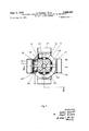
- FIG. 1 is a plan view of a distilling or rectifying column having a condenser which embodies one form of the invention, a portion of the condenser being broken away;
- FIG. 2 is a partly side elevational and partly vertical sectional view as seen in the direction of arrows from the line IIII of FIG. 1;
- FIG. 3 is a plan view of a second column having a modified condenser a portion of which is broken away;
- FIG. 4 is a partly side elevational and partly vertical sectional view as seen in the direction of arrows from the line IVIV of FIG. 3;
- FIG. 5 is a plan view of a third column having still another condenser a portion of which is broken away;
- FIG. 6 is a partly side elevational and partly vertical sectional view as seen in the direction of arrows from the line VIVI of FIG. 5;
- FIG. 7 is a plan view of a fourth column having a different condenser a portion of which is broken away.
- FIG. 8 is a partly elevational and partly vertical sectional view as seen in the direction of arrows from the line VIII-VIII of FIG. 7.
- the distilling or rectifying column of FIGS. 1 and 2 comprises an upright shell 2 Whose upper end portion includes a cap 3.
- the hot head fraction rises in the column toward and into the interior of the cap 3 which carries a centrally located upwardly extending vertical tubular riser 4 for the head fraction.
- the parts of the improved air-cooled condenser 1 are mounted on the riser 4 and on the cap 3.
- the upper end portion of the riser 4 carries and communicates with radially outwardly extending supply conduits 5 each of which delivers the head fraction to the heat-exchanging pipes in one of six discrete condensing sections or units 6.
- each condensing unit 6 extend vertically downwardly and receive the head fraction by way of distributing chambers 7 which communicate with the outer ends of the respective supply conduits 5.
- the pipes in the condensing units 6 are round and are grouped or bunched together to form flat packages which extend substantially tangentially of the shell 2 and enclose a centrally located hexagonal compartment 8.
- This compartment is surrounded by a housing having a bottom wall 9 below the compartment and a cover or dome 13.
- the bottom Wall 9 is of annular shape and has a central opening which sealingly receives the riser 4.
- the reference numbers 10a, 10b respectively indicate the outer and inner sides of the groups of heat-exchanging pipes in the condensing units 6.
- the upper ends of the groups of pipes are indicated at 16 and their lower ends at 12.
- the marginal portions of the bottom wall 9 are welded or otherwise sealingly secured to the lower ends 12 of the pipes in the units 6 so that the compartment 8 is completely sealed from below.
- the marginal portions of the cover 13 are welded to the distributing chambers 7 for the head fraction.
- the pipes in the groups of the condensing units 6 have uneven external surfaces to promote the exchange of heat between the atmospheric air and the head fraction. This is achieved by providing the pipes with fins, ribs or like projections.
- the lower ends of the pipes are in communication with collecting chambers 11 which discharge the condensate into a conduit 20.
- the latter returns some condensate as a reflux into the shell 2 and the remainder into a collecting vessel, not shown.
- the condensate is caused to enter the shell 2 and the collecting vessel by gravity flow; this saves the expenses for pumps and reduces the energy requirements of the condenser.
- the central portion of the cover 13 supports a shielding ring 14 which surrounds a fan 15 or another suitable air circulating device. If desired, the cover 13 can carry two or more fans.
- the fan 15 draws air from the compartment 8 (see the arrows y) and the compartment 8 receives atmospheric air which flows across the pipes in the groups of the condensing units 6 (arrows x). Such air causes the condensation of head fraction which enters the pipes by way of the respective distributing chambers 7.
- the condenser 1 further comprises an enclosure 17a which shields the outer sides 10a of pipes in the groups of the condensing units 6 from rain, snow, sun, wind and other atmospheric influences.
- the enclosure 17a comprises a circumferentially complete outer panel 19a which slopes downwardly and outwardly from a ring-shaped horizontal top panel 18a and is sealingly connected thereto.
- the top panel 18a is welded to the upper ends 16 of the groups of pipes in the condensing units 6.
- the lower end portion of the enclosure 17a is provided with an annular inlet 23a which admits atmospheric air in the directions indicated by the arrows x.
- the enclosure 17a can be said to comprise six interconnected discrete enclosures, one for each condensing unit 6 and each having a slot-shaped inlet for admission of atmospheric air against the outer sides 10a of the respective groups of pipes.
- the lower end portion of the outer panel 1% extends at least to the level of the lower ends 12 of pipes in the condensing units 6.
- Mixing of cool atmospheric air which enters the enclosure 17a by way of the inlet 23a (arrows x) with heated air which is drawn from the compartment 8 by the fan 15 (arrows y) is highly unlikely because the heated air tends to rise.
- Such absence of mixing of hot and cool air enhances the efiiciency of the condenser 1.
- the cool air flows across the pipes in the groups of the condensing units 6 and is thereby heated while simultaneously causing uniform condensation of the head fraction in all sections of the condenser 1. This is attributed to the fact that cool air which is drawn upwardly through the inlet 23a is not influenced by winds, sun, rain, snow or the like.
- the outer panel 19a of the enclosure 17a slopes outwardly and downwardly from the marginal portion of the top panel 18a. Consequently, the width of the annular space 117a in the enclosure 17a decreases in a direction from the annular inlet 23a toward the underside of the top panel 18a.
- Such uniform pressure of atmospheric air at the outer sides of the heat-exchanging pipes promotes uniform condensation-of the head fraction in each section of the condenser.
- the condenser 1 of FIGS. 1-2 may comprise more than six condensing units 6 or that the number of such units can be five or less.
- the circumferentially complete enclosure 17a is particularly suited for use in large condensers which comprise a substantial number of polygonally arranged condensing units.
- the condenser 1 of FIGS. 1 and 2 is condensatorically connected with the shell 2, i.e., in such a way that the head fraction ascends from the cap 3 into the riser 4, thereupon flows in the horizontal supply condiuts 5 to enter the distributing chambers 7, and flows downwardly in the pipes of the condensing units 6.
- the flow of the head fraction is concurrent with the flow of the condensate.
- the reflux from the conduit 20 is returned into the uppermost exchangeable trays (not shown) in the shell 2.
- the basic design of the condenser 101 shown in FIGS. 3 and 4 is quite similar to that of the condenser 1.
- the main difference is that the condenser 101 comprises only four condensing units 106 wherein the heat-exchanging pipes are inclined downwardly and inwardly toward the cap 103 of the shell 102, and that the condenser 101 comprises a modified enclosure for the condensing units 106.
- the enclosure comprises four discrete enclosures or envelopes 17b, one for each condensing unit 106, and the housing intermediate walls which seal the compartment 108 in the regions between the lateral edge portions of the condensing units.
- Each enclosure 17b has a substantially horizontal rectangular top panel 18b which is sealingly secured to the upper ends 116 of the group of pipes in the respective unit 106, a vertical rectangular outer panel 19b which extends downwardly from the outermost portion of the respective top panel 18b, and two lateral panels 24 which connect the vertical edges of the outer panel 1% with the corresponding edge portions of the associated condensing unit 106. Since the heat exchanging pipes are inclined downwardly and inwardly whereas the outer panels 1% of the enclosures 17b are vertical, the width of the space 117b between the outer side 110a of each group of pipes and the corresponding outer panel 19b decreases from the slot-shaped inlet 23b toward the upper end 116 of the associated group. This is advantageous for reasons which were explained in connection with FIGS. 1 and 2. Thus, a tapering space at the outer side of each group of pipes can be obtained by employing a vertical outer panel in association with inclined pipes or vice versa.
- the aforementioned intermediate walls of the housing are shown at 22. These walls extend upwardly from the bottom wall 109 of the housing for the compartment 108 and diverge at the rate determined by the inclination of condensing units 106.
- the upper end portions of the intermediate walls 22 are welded to the cover 113 which carries a ring 114 extending around a fan 115.
- the compartment 108 can receive air only by way of inlets 23b (arrow x) and gaps between the pipes in the four condensing units 106 whereby the air is heated and enters the compartment 108 to be evacuated by the fan 115 through the cover 113 (arrows y).
- the inlets 23b are elongated slots of rectangular outline and are provided at the general level of the lower ends 112 of pipes in the groups of the condensing units 106.
- FIGS. 3-4 The remaining parts of the structure shown in FIGS. 3-4 are analogous to the parts shown in FIGS. 1-2 and are denoted by similar reference characters plus 100.
- Discrete inclosures for the condensing units of a column-head condenser are particularly suited for use in condensers wherein the number of condensing units is relatively small. This saves the expenditure for a circumferentially complete enclosure.
- condensers wherein the condensing units comprise inclined heat-exchanging pipes are more elfective than the condensers with vertically extending pipes.
- the vertically extending heat-exchanging pipes can be accommodated in a small area; therefore, they normally find use in large condensers with a substantial number of condensing units.
- the condenser 201 of FIGS and 6 is dephlegmatorically connected with the shell 202.
- the collecting chambers 211 at the lower ends 212 of the groups of heat-exchanging pipes in the condensing units 206 receive vapors from the cap 203 of the shell 202.
- Such vapors rise in the pipes all the way to the distributing chambers 207 and/or undergo condensation While they rise in such pipes. Consequently, the descending condensate flows countercurrent to the rising head fraction.
- conduits 21 which also serve to deliver the head fraction to the condensing units 206.
- the distributing chambers 207 can be connected to each other by a ring-shaped pipe which, when the column is a vacuum column, are connected to a suction generating device (not shown).
- the construction of the enclosure 217a is the same as that of the enclosure 17a shown in FIGS. 1 and 2. The same applies for the housing which encloses the compartment 208. With the exception of the conduit 21, all parts of the structure shown in FIGS. 5 and 6 are denoted by reference numerals similar to those employed in FIGS. 1-2 plus 200.
- FIGS. 7 and 8 illustrate a condenser 301 which is dephlegmatically connected with the shell 302 and is analogous to the condenser 101 of FIGS. 3-4 excepting that it comprises only two condensing units 306 which are disposed diametrically opposite each other with reference to the axis of the shell.
- the heat-exchanging pipes in the condensing units 306 are inclined downwardly and inwardly toward the cap 303 of the shell 203.
- the compartment 308 below the cover 313 is enclosed in part by intermediate walls 322. All other parts of the condenser 301 are denoted by reference numerals similar to those used in FIGS. 3-4 plus 200.
- each condenser can employ two or more discrete fans all of which can be mounted in the cover of the housing.
- a combination comprising an upright tubular shell wherein the hot head fraction rises, said shell having a vertical axis and an upper end portion, a condenser mounted on said upper end portion and comprising a plurality of condensing units each having a group of elongated heat exchanging pipes communicating with said upper end portion to receive the head fraction, said pipes having extended external surfaces and said groups being substantially normal to radial planes including the axis of said shell and defining an inner compartment above said shell, a housing including a bottom wall below and a cover above said compartment, a substantially imperforate enclosure outwardly spaced from said groups and protecting said groups from the influence of adverse atmospheric conditions and having a lower part provided with air inlet means, and air circulating means mounted in said cover and arranged to draw atmospheric air through said air inlet means into said enclosure whereby such air flows transversely across said pipes into said compartment to effect condensation of the head fraction in the pipes, said air being evacuated from said compartment by said circulating means in said cover
- said housing further comprises intermediate walls extending between said bottom wall and said cover intermediate said groups.
- said air inlet means comprises discrete slots extending lengthwise of the respective groups.
- said enclosure defines at least one space which tapers upwardly from said air inlet means to effect uniform distribution and pressure of air along the outer sides of said groups.
- said enclosure defines a plurality of discrete spaces each outwardly spaced from one of said groups and each tapering upwardly from the air inlet means to effect uniform distribution and pressure of air at the outer sides of the respective groups.
- said groups of pipes are disposed in substantially vertical planes and said enclosure includes outer panel means outwardly spaced from said groups and being inclined with reference to the outer sides of such groups so as to form therewith at least one space whose cross-sectional area decreases upwardly from said air inlet means.
- a combination as defined in claim 1 further comprising vertical riser means communicating with and extending upwardly from said upper end portion into said compartment, said riser means being supportingly connected with said units and communicating with said pipes to admit the head fraction thereto.
- a combination as defined in claim 12, wherein said enclosure comprises a top panel sealingly secured to the uppermost portions of said groups and a circumferential outer panel extending downwardly from said top panel at least to the level of the lowermost portions of said groups.
- said enclosure comprises a plurality of discrete sections each outwardly spaced from one of said groups and said air inlet means comprises discrete inlets in said sections.
- each section of said enclosure comprises a substantially horizontal top panel sealingly secured to the uppermost portion of the respective group, an outer panel extending downwardly from the top panel at least to the level of the lowermost portion of the respective group, and lateral panels extending between said outer panel and the lateral edge portions of the respective group.
Landscapes
- Chemical & Material Sciences (AREA)
- Chemical Kinetics & Catalysis (AREA)
- Heat-Exchange Devices With Radiators And Conduit Assemblies (AREA)
- Vaporization, Distillation, Condensation, Sublimation, And Cold Traps (AREA)
Abstract
A distilling or rectifying column wherein the upper end portion of the shell carries an air-cooled condenser for the head fraction. The condenser has several discrete condensing units whose heat-exchanging pipes communicate with the shell to receive the head fraction and discharge condensate into collecting chambers. Each condensing unit is surrounded by an enclosure which has an inlet below the pipes and shields the outer sides of the pipes from wind, sun and precipitation. The air is drawn through the inlets by one or more fans which are mounted in a dome located above a compartment which is surrounded by the condensing units. The spaces defined by the enclosures at the outer sides of pipes in the condensing units taper upwardly from the inlets to insure uniform distribution of air pressure. The enclosures can be united into a single annular enclosure which completely surrounds the condensing units.
Description
Sept. 5, 1972 ss ETAL 3,689,367
AIR-COOLED CONDENSER FOR HEAD FRACTIONS IN RECTIFYING OR DISTILLING COLUMNS 7 Sheets-Sheet 1 Filed July 30, 1970 Fig.1
INVEN TORS HARRY knsfl" BY sear msseo 4-444! filler) Sept. 5, 1972 H. KASSAT ETAL 3,689,367
AIR-COOLED CONDENSER FOR HEAD FRACTIONS IN RECTIFYING on DISTILLINGV cowmns Filed July 30, 1970 7 Sheets-Sheet 2 VAPORS CONDENSATE Fig.2
IN VEN roRs man; #4507 BY Ennr H15 Sept. 5, 1972 H. KASSAT ETAL 3,689,367
AIR-COOLED CONDENSER FOR HEAD FRACTIQNS IN RECTIFYING on DISTILLING COLUMNS Filed July 30, 1970 .7 Sheets-Sheet 5 11Gb 22 v 104 Fig. 3
INVENTOR9 v (4 (L-ll" A M") Sept. 5, 1972 ss -r EI'AL 3,689,367
AIR-(300L131) CONDENSER FOR HEAD FRACTIONS IN RECTIFYING 0R DISTILLING COLUMNS Filed July so, 1970 .7 sheets-sheet 4 Fig. 4
/N VEN TORS BY 62/1137" 1059 E0 Sept. 5, 1972 H. KASSAT AL 3,689,367 AIR-COOLED CONDENSER FOR HEAD FRACTIONS IN RECTIFYING OR DISTILLING COLUMNS Filed July so, 1970 7 Sheets-Sheet 5 I o d o x v o Y 0 214 O 206 215 VI I O! v i 217a o L J 0 210m 0 o o Fig.5
Sept. 5, 1972 H. KASSAT I- 3,689,367 AIR-COOLED CONDENSER FOR HEAD FRACTIONS IN RECTIFYING OR DISTILLING COLUMNS Filed July so, 1970 7 Sheets-Sheet 6 321. 31s 3d] 322 l 321 l v T F|g.7 VIII INVENTORS may hear Eta Jr kl: SE6
Sept. 5, 1972 ss -r E.TAL 3,689,367
AIR-COOLED CONDENSER FOR HEAD FRACTIONS IN RECTIFYING 0R DISTILLING COLUMNS Filed July 30, 1970 -7 Sheets-Sheet 7 A I I -v vi 313 310a an 321 324 Fig.8
INVENTORS Patented Sept. 5, 1972 3,689,367 AIR-COOLED CONDENSER FOR HEAD FRAC- TIONS IN RECTIFYING OR DISTILLING COLUMNS Harry Kassat, Bochum, and Ernst Kissel, Ludwigshafen, Germany, assignors to 'Gea Luftkuhlergesellschaft Happel G.m.b.H. & Co. K.G., Bochum, Germany Filed July 30, 1970, Ser. No. 59,632 Claims priority, application Germany, Sept. 17, 1969, P 19 46 915.9 Int. Cl. F24h 3/06; F28b; F24f 13/12; B01d 3/00 U.S. Cl. 202-185 B 15 Claims ABSTRACT OF THE DISCLOSURE A distilling or rectifying column wherein the upper end portion of the shell carries an air-cooled condenser for the head fraction. The condenser has several discrete condensing units whose heat-exchanging pipes communicate with the shell to receive the head fraction and discharge condensate into collecting chambers. Each condensing unit is surrounded by an enclosure which has an inlet below the pipes and shields the outer sides of the pipes from wind, sun and precipitation. The air is drawn through the inlets by one or more fans which are mounted in a dome located above a compartment which is surrounded by the condensing units. The spaces defined by the enclosures at the outer sides of pipes in the condensing units taper upwardly from the inlets to insure uniform distribution of air pressure. The enclosures can be united into a single annular enclosure which completely surrounds the condensing units.
CROSS-REFERENCE TO RELATED APPLICATION The condenser of the present invention belongs to the class of condensers as disclosed in the copending application Ser. No. 58,418, filed July 27, 1970 by Harry Kassat et al., and owned by the assignee of the present application.
BACKGROUND OF THE INVENTION The present invention relates to improvements in aircooled condensers for head fractions or low boiling fractions in rectifying or distilling columns. More particularly, the invention relates to improvements in air-cooled condensers which are designed to be mounted on top of the shells of rectifying or distilling columns.
Various types of air-cooled condensers (so-called column-head condensers) have found widespread acceptance in distilling and rectifying plants. An advantage of such condensers in that they need not be provided with separate frames or supports because they can be convenientlyinstalled on top of the shell of a distilling or rectifying column. Moreover, such condensers occupy space which is otherwise unused and the head fraction can enter the heat-exchanging pipes of such condensers by way of short conduits to thus reduce pressure losses.
On the other hand, presently known condensers for use on the shell of a distilling or rectifying column exhibit a number of serious drawbacks. For example, wind, rain, snow or other precipitation is likely to exert undue influence on the cooling action and on the temperature of condensate. This is due to the fact that the heat-exchanging pipes of such condensers are normally disposed in groups which are located in vertical planes and form the Sides of a polygon whose center is located on the axis of the shell. The outer sides of the groups (i.e., of the pipes in such groups) are fully exposed so that a hot sun, a strong wind or a driving rain is quite likely to affect the condensation of head fractions. Since the condensers are mounted at a substantial distance above the ground, the influence of wind, sun and/or precipitation is even more pronounced. The situation is the same with certain other types of condensers which comprise only two parallel groups of heat-exchanging pipes and vertical walls which extend between the vertical edges of the groups to form therewith a compartment into which the atmospheric air is drawn by a fan so that the air flows across the pipes and effects condensation of the head fraction. It was found that, when such conventional condensers are to be operated in strong wind, cold rain or snow, one or more groups of pipes will be cooled much more intensively than the remaining group or groups of pipes and that this can result in excessive undercooling and eventual freezing of condensate. The remaining groups of pipes then deliver a greatly reduced quantity of condensate or the temperature of condensate in the pipes which are protected from adverse atmospheric conditions exceeds a desirable temperature. Therefore, the above described conventional condensers cannot be used for treatment of certain head fractions, particularly those whose temperature must be maintained within a rather narrow range.
SUMMARY OF THE INVENTION An object of the invention is to provide a novel and improved air-cooled condenser which, even though mounted on top of the shell in a distilling or rectifying column, is capable of yielding condensate whose temperature can be maintained within a desired range.
Another object of the invention is to provide a condenser whose operation is not unduly influenced by rain, snow, sleet, wind, sun or other atmospheric conditions.
A further object of the invention is to provide a condenser which can be readily installed in presently known distilling or rectifying columns.
An additional object of the invention is to provide a condenser which is more eflicient than presently known condensers for use on the shells of distilling or rectifying columns.
The invention is embodied in a distilling or rectifying column which comprises an upright shell wherein the hot head fraction rises toward and into the upper end portion of the shell, a condenser mounted on the upper end portion of the shell and comprising a plurality of preferably independent condensing units each having at least one group of elongated heat-exchanging pipes communicating with the upper end portion (for example, by way of one or more vertical risers which communicate with the upper end portion of the shell and can also serve to carry at least a portion of the weight of the condenser) to receive the head product. The pipes are preferably provided with uneven (finned, ribbed or similarly configurated) external surfaces to promote the exchange of heat with surrounding air and the groups of pipes preferably extend substantially tangentially of the shell and define a compartment at a level above the upper end portion of the shell. The condenser further comprises a housing having a bottom wall below and a cover or dome above the compartment, enclosures each of which is outwardly adjacent to one of the groups of pipes and has in its lower end a preferably slot-shaped inlet for the admission of atmospheric air, and air circulating means including one or more fans mounted in the cover of the housing to draw air through the inlets whereby such air flows across the pipes to effect condensation of the head fraction and is evacuated by way of the cover. The column further comprises collecting means for receiving the condensate from the heat-exchanging pipes.
The aforementioned enclosures may form a circumferentially complete enclosure around the groups of pipes, and the inlets may form a single annular inlet in the lower end of such enclosure. The cross-sectional area of the space within each enclosure preferably decreases in a direction upwardly from the inlet to insure that each pipe is traversed by currents of air at the same pressure.
The novel features which are considered as characteristic of the invention are set forth in particular in the appended claims. The improved condenser itself, however, both as to its construction and its mode of operation, together with additional features and advantages thereof, will be best understood upon perusal of the following detailed description of certain specific embodiments with reference to the accompanying drawing.
BRIEF DESCRIPTION OF THE DMWING FIG. 1 is a plan view of a distilling or rectifying column having a condenser which embodies one form of the invention, a portion of the condenser being broken away;
FIG. 2 is a partly side elevational and partly vertical sectional view as seen in the direction of arrows from the line IIII of FIG. 1;
FIG. 3 is a plan view of a second column having a modified condenser a portion of which is broken away;
FIG. 4 is a partly side elevational and partly vertical sectional view as seen in the direction of arrows from the line IVIV of FIG. 3;
FIG. 5 is a plan view of a third column having still another condenser a portion of which is broken away;
FIG. 6 is a partly side elevational and partly vertical sectional view as seen in the direction of arrows from the line VIVI of FIG. 5;
FIG. 7 is a plan view of a fourth column having a different condenser a portion of which is broken away; and
FIG. 8 is a partly elevational and partly vertical sectional view as seen in the direction of arrows from the line VIII-VIII of FIG. 7.
DESCRIPTION OF THE PREFERRED EMBODIMENTS The distilling or rectifying column of FIGS. 1 and 2 comprises an upright shell 2 Whose upper end portion includes a cap 3. The hot head fraction rises in the column toward and into the interior of the cap 3 which carries a centrally located upwardly extending vertical tubular riser 4 for the head fraction. The parts of the improved air-cooled condenser 1 are mounted on the riser 4 and on the cap 3. The upper end portion of the riser 4 carries and communicates with radially outwardly extending supply conduits 5 each of which delivers the head fraction to the heat-exchanging pipes in one of six discrete condensing sections or units 6. The heat-exchanging pipes of each condensing unit 6 extend vertically downwardly and receive the head fraction by way of distributing chambers 7 which communicate with the outer ends of the respective supply conduits 5. The pipes in the condensing units 6 are round and are grouped or bunched together to form flat packages which extend substantially tangentially of the shell 2 and enclose a centrally located hexagonal compartment 8. This compartment is surrounded by a housing having a bottom wall 9 below the compartment and a cover or dome 13. The bottom Wall 9 is of annular shape and has a central opening which sealingly receives the riser 4.
The reference numbers 10a, 10b respectively indicate the outer and inner sides of the groups of heat-exchanging pipes in the condensing units 6. The upper ends of the groups of pipes are indicated at 16 and their lower ends at 12. The marginal portions of the bottom wall 9 are welded or otherwise sealingly secured to the lower ends 12 of the pipes in the units 6 so that the compartment 8 is completely sealed from below. The marginal portions of the cover 13 are welded to the distributing chambers 7 for the head fraction. The pipes in the groups of the condensing units 6 have uneven external surfaces to promote the exchange of heat between the atmospheric air and the head fraction. This is achieved by providing the pipes with fins, ribs or like projections. The lower ends of the pipes are in communication with collecting chambers 11 which discharge the condensate into a conduit 20. The latter returns some condensate as a reflux into the shell 2 and the remainder into a collecting vessel, not shown. The condensate is caused to enter the shell 2 and the collecting vessel by gravity flow; this saves the expenses for pumps and reduces the energy requirements of the condenser.
The central portion of the cover 13 supports a shielding ring 14 which surrounds a fan 15 or another suitable air circulating device. If desired, the cover 13 can carry two or more fans. The fan 15 draws air from the compartment 8 (see the arrows y) and the compartment 8 receives atmospheric air which flows across the pipes in the groups of the condensing units 6 (arrows x). Such air causes the condensation of head fraction which enters the pipes by way of the respective distributing chambers 7.
In accordance with a feature of the invention, the condenser 1 further comprises an enclosure 17a which shields the outer sides 10a of pipes in the groups of the condensing units 6 from rain, snow, sun, wind and other atmospheric influences. The enclosure 17a comprises a circumferentially complete outer panel 19a which slopes downwardly and outwardly from a ring-shaped horizontal top panel 18a and is sealingly connected thereto. The top panel 18a is welded to the upper ends 16 of the groups of pipes in the condensing units 6. The lower end portion of the enclosure 17a is provided with an annular inlet 23a which admits atmospheric air in the directions indicated by the arrows x. The enclosure 17a can be said to comprise six interconnected discrete enclosures, one for each condensing unit 6 and each having a slot-shaped inlet for admission of atmospheric air against the outer sides 10a of the respective groups of pipes.
The lower end portion of the outer panel 1% extends at least to the level of the lower ends 12 of pipes in the condensing units 6. Mixing of cool atmospheric air which enters the enclosure 17a by way of the inlet 23a (arrows x) with heated air which is drawn from the compartment 8 by the fan 15 (arrows y) is highly unlikely because the heated air tends to rise. Such absence of mixing of hot and cool air enhances the efiiciency of the condenser 1. The cool air flows across the pipes in the groups of the condensing units 6 and is thereby heated while simultaneously causing uniform condensation of the head fraction in all sections of the condenser 1. This is attributed to the fact that cool air which is drawn upwardly through the inlet 23a is not influenced by winds, sun, rain, snow or the like.
As stated before, the outer panel 19a of the enclosure 17a slopes outwardly and downwardly from the marginal portion of the top panel 18a. Consequently, the width of the annular space 117a in the enclosure 17a decreases in a direction from the annular inlet 23a toward the underside of the top panel 18a. This is desirable because such inclination of the panel 19a with reference to the outer sides 10:: of pipes in the condensing units 6 insures that the air pressure in each region of each outer side 10a is constant all the way from the lower end 12. to the upper end 16 of the respective group. Such uniform pressure of atmospheric air at the outer sides of the heat-exchanging pipes promotes uniform condensation-of the head fraction in each section of the condenser.
Hot air which is forced by the fan 15 to flow upwardly through the central opening of the cover 13 normally prevents penetration of rain, snow or other precipitation into the compartment 8. It is clear that the condenser 1 of FIGS. 1-2 may comprise more than six condensing units 6 or that the number of such units can be five or less. The circumferentially complete enclosure 17a is particularly suited for use in large condensers which comprise a substantial number of polygonally arranged condensing units.
The condenser 1 of FIGS. 1 and 2 is condensatorically connected with the shell 2, i.e., in such a way that the head fraction ascends from the cap 3 into the riser 4, thereupon flows in the horizontal supply condiuts 5 to enter the distributing chambers 7, and flows downwardly in the pipes of the condensing units 6. Thus, the flow of the head fraction is concurrent with the flow of the condensate. The reflux from the conduit 20 is returned into the uppermost exchangeable trays (not shown) in the shell 2.
The basic design of the condenser 101 shown in FIGS. 3 and 4 is quite similar to that of the condenser 1. The main difference is that the condenser 101 comprises only four condensing units 106 wherein the heat-exchanging pipes are inclined downwardly and inwardly toward the cap 103 of the shell 102, and that the condenser 101 comprises a modified enclosure for the condensing units 106. The enclosure comprises four discrete enclosures or envelopes 17b, one for each condensing unit 106, and the housing intermediate walls which seal the compartment 108 in the regions between the lateral edge portions of the condensing units. Each enclosure 17b has a substantially horizontal rectangular top panel 18b which is sealingly secured to the upper ends 116 of the group of pipes in the respective unit 106, a vertical rectangular outer panel 19b which extends downwardly from the outermost portion of the respective top panel 18b, and two lateral panels 24 which connect the vertical edges of the outer panel 1% with the corresponding edge portions of the associated condensing unit 106. Since the heat exchanging pipes are inclined downwardly and inwardly whereas the outer panels 1% of the enclosures 17b are vertical, the width of the space 117b between the outer side 110a of each group of pipes and the corresponding outer panel 19b decreases from the slot-shaped inlet 23b toward the upper end 116 of the associated group. This is advantageous for reasons which were explained in connection with FIGS. 1 and 2. Thus, a tapering space at the outer side of each group of pipes can be obtained by employing a vertical outer panel in association with inclined pipes or vice versa.
The aforementioned intermediate walls of the housing are shown at 22. These walls extend upwardly from the bottom wall 109 of the housing for the compartment 108 and diverge at the rate determined by the inclination of condensing units 106. The upper end portions of the intermediate walls 22 are welded to the cover 113 which carries a ring 114 extending around a fan 115. The compartment 108 can receive air only by way of inlets 23b (arrow x) and gaps between the pipes in the four condensing units 106 whereby the air is heated and enters the compartment 108 to be evacuated by the fan 115 through the cover 113 (arrows y). The inlets 23b are elongated slots of rectangular outline and are provided at the general level of the lower ends 112 of pipes in the groups of the condensing units 106.
The remaining parts of the structure shown in FIGS. 3-4 are analogous to the parts shown in FIGS. 1-2 and are denoted by similar reference characters plus 100.
Discrete inclosures for the condensing units of a column-head condenser are particularly suited for use in condensers wherein the number of condensing units is relatively small. This saves the expenditure for a circumferentially complete enclosure.
As a rule, condensers wherein the condensing units comprise inclined heat-exchanging pipes are more elfective than the condensers with vertically extending pipes. However, the vertically extending heat-exchanging pipes can be accommodated in a small area; therefore, they normally find use in large condensers with a substantial number of condensing units.
The condenser 201 of FIGS and 6 is dephlegmatorically connected with the shell 202. Thus, the collecting chambers 211 at the lower ends 212 of the groups of heat-exchanging pipes in the condensing units 206 receive vapors from the cap 203 of the shell 202. Such vapors rise in the pipes all the way to the distributing chambers 207 and/or undergo condensation While they rise in such pipes. Consequently, the descending condensate flows countercurrent to the rising head fraction. The
condensate is withdrawn by way of conduits 21 which also serve to deliver the head fraction to the condensing units 206. The distributing chambers 207 can be connected to each other by a ring-shaped pipe which, when the column is a vacuum column, are connected to a suction generating device (not shown).
The construction of the enclosure 217a is the same as that of the enclosure 17a shown in FIGS. 1 and 2. The same applies for the housing which encloses the compartment 208. With the exception of the conduit 21, all parts of the structure shown in FIGS. 5 and 6 are denoted by reference numerals similar to those employed in FIGS. 1-2 plus 200.
FIGS. 7 and 8 illustrate a condenser 301 which is dephlegmatically connected with the shell 302 and is analogous to the condenser 101 of FIGS. 3-4 excepting that it comprises only two condensing units 306 which are disposed diametrically opposite each other with reference to the axis of the shell. The heat-exchanging pipes in the condensing units 306 are inclined downwardly and inwardly toward the cap 303 of the shell 203. The compartment 308 below the cover 313 is enclosed in part by intermediate walls 322. All other parts of the condenser 301 are denoted by reference numerals similar to those used in FIGS. 3-4 plus 200.
The enclosures are preferably made of thin sheet metal; however, we also contemplate using enclosures consisting at least in part of synthetic plastic material, asbestos or any other suitable substance. Moreover, and as mentioned above, each condenser can employ two or more discrete fans all of which can be mounted in the cover of the housing.
Without further analysis, the foregoing will so fully reveal the gist of the present invention that others can, by applying current knowledge, readily adapt it for various applications without omitting features which fairly constitute essential characteristics of the eneric and specific aspects of our contribution to the art and, therefore, such adaptations should and are intended to be comprehended within the meaning and range of equivalence of the claims.
What is claimed as new and desired to be protected by Letters Patent is set forth in the appended claims:
1. In a distilling or rectifying column, a combination comprising an upright tubular shell wherein the hot head fraction rises, said shell having a vertical axis and an upper end portion, a condenser mounted on said upper end portion and comprising a plurality of condensing units each having a group of elongated heat exchanging pipes communicating with said upper end portion to receive the head fraction, said pipes having extended external surfaces and said groups being substantially normal to radial planes including the axis of said shell and defining an inner compartment above said shell, a housing including a bottom wall below and a cover above said compartment, a substantially imperforate enclosure outwardly spaced from said groups and protecting said groups from the influence of adverse atmospheric conditions and having a lower part provided with air inlet means, and air circulating means mounted in said cover and arranged to draw atmospheric air through said air inlet means into said enclosure whereby such air flows transversely across said pipes into said compartment to effect condensation of the head fraction in the pipes, said air being evacuated from said compartment by said circulating means in said cover, said cover being sufiiciently close to said groups of pipes to confine at least the major part of the air to flow from said inner compartment into the range of said circulating means; and collecting means for receiving the condensate from said pipes.
2. A combination as defined in claim 1, wherein said groups of pipes are located in substantially vertical planes.
3. A combination as defined in claim 1, wherein said groups of pipes are located in inclined planes.
4. A combination as defined in claim 1, wherein said housing further comprises intermediate walls extending between said bottom wall and said cover intermediate said groups.
5. A combination as defined in claim 1, wherein said air inlet means comprises discrete slots extending lengthwise of the respective groups.
6. A combination as defined in claim 1, wherein said enclosure defines at least one space which tapers upwardly from said air inlet means to effect uniform distribution and pressure of air along the outer sides of said groups.
7. A combination as defined in claim 1, wherein said enclosure defines a plurality of discrete spaces each outwardly spaced from one of said groups and each tapering upwardly from the air inlet means to effect uniform distribution and pressure of air at the outer sides of the respective groups.
8. A combination as defined in claim 1, wherein said groups of pipes are disposed in substantially vertical planes and said enclosure includes outer panel means outwardly spaced from said groups and being inclined with reference to the outer sides of such groups so as to form therewith at least one space whose cross-sectional area decreases upwardly from said air inlet means.
9. A combination as defined in claim 1, wherein said groups of pipes are disposed in planes which diverge upwardly with reference to said shell and said enclosure comprises outer panel means defining with said groups of pipes at least one space whose cross-sectional area de creases upwardly from said air inlet means.
10. A combination as defined in claim 1, wherein the number of said condensing units exceeds two and each of said groups comprises at least one bundle of interconnected pipes.
11. A combination as defined in claim 1, further comprising vertical riser means communicating with and extending upwardly from said upper end portion into said compartment, said riser means being supportingly connected with said units and communicating with said pipes to admit the head fraction thereto.
12. A combination as defined in claim 1, wherein said enclosure forms a circumferentially complete annulus around said groups and said air inlet means is a circumferentially complete slot provided in the lower end of said enclosure.
13. A combination as defined in claim 12, wherein said enclosure comprises a top panel sealingly secured to the uppermost portions of said groups and a circumferential outer panel extending downwardly from said top panel at least to the level of the lowermost portions of said groups.
14. A combination as defined in claim 1, wherein said enclosure comprises a plurality of discrete sections each outwardly spaced from one of said groups and said air inlet means comprises discrete inlets in said sections.
15. A combination as defined in claim 14, wherein each section of said enclosure comprises a substantially horizontal top panel sealingly secured to the uppermost portion of the respective group, an outer panel extending downwardly from the top panel at least to the level of the lowermost portion of the respective group, and lateral panels extending between said outer panel and the lateral edge portions of the respective group.
References Cited UNITED STATES PATENTS 3,165,455 1/1965 Rose et a1 202-189 3,175,960 3/1965 Kassat 202-189 3,280,900 10/1966 Wartenberg -122 FOREIGN PATENTS 677,166 12/1963 Canada 202- B NORMAN YUDKOFF, Primary Examiner J. SOFER, Assistant Examiner US. Cl. X.R.
Applications Claiming Priority (1)
| Application Number | Priority Date | Filing Date | Title |
|---|---|---|---|
| DE19691946915 DE1946915B2 (en) | 1969-09-17 | 1969-09-17 | AIR-COOLED CONDENSER FOR THE HEAD PRODUCT OF A DISTILLATION OR RECTIFICATION COLUMN |
Publications (1)
| Publication Number | Publication Date |
|---|---|
| US3689367A true US3689367A (en) | 1972-09-05 |
Family
ID=5745660
Family Applications (1)
| Application Number | Title | Priority Date | Filing Date |
|---|---|---|---|
| US59632A Expired - Lifetime US3689367A (en) | 1969-09-17 | 1970-07-30 | Air-cooled condenser for head fractions in rectifying or distilling columns |
Country Status (4)
| Country | Link |
|---|---|
| US (1) | US3689367A (en) |
| BE (1) | BE755737A (en) |
| DE (1) | DE1946915B2 (en) |
| GB (1) | GB1317766A (en) |
Cited By (11)
| Publication number | Priority date | Publication date | Assignee | Title |
|---|---|---|---|---|
| US3925523A (en) * | 1973-11-12 | 1975-12-09 | Marley Co | Opposed air path wet-dry cooling tower and method |
| US3935077A (en) * | 1974-04-29 | 1976-01-27 | Dennison Clifford C | Automatic water distiller |
| US3939906A (en) * | 1973-12-28 | 1976-02-24 | The Lummus Company | Air cooled exchanger |
| US4159738A (en) * | 1976-03-08 | 1979-07-03 | Societe Des Condenseurs Delas S.A. | Fan-assisted forced flow air-cooling heat exchanger system |
| US5762762A (en) * | 1996-03-19 | 1998-06-09 | The Breithaupt Family Trust | Distillation apparatus |
| US6548225B1 (en) * | 1997-02-14 | 2003-04-15 | Jds Uniphase Pty Limited | Method and apparatus for writing gratings |
| US20060243430A1 (en) * | 2005-04-04 | 2006-11-02 | Michel Vouche | Air-cooled condenser |
| US20080210403A1 (en) * | 2005-05-23 | 2008-09-04 | Gea Energietechnil Gmbh | Condensation Plant |
| US20110226450A1 (en) * | 2010-03-22 | 2011-09-22 | Spx Cooling Technologies, Inc. | Apparatus and method for a natural draft air cooled condenser cooling tower |
| US20120048716A1 (en) * | 2010-08-26 | 2012-03-01 | Integroenergy Group, Inc. | Method of removing heat during ethanol production |
| US20120160464A1 (en) * | 2009-09-01 | 2012-06-28 | Gea Energietechnik Gmbh | Air condenser |
Families Citing this family (1)
| Publication number | Priority date | Publication date | Assignee | Title |
|---|---|---|---|---|
| RU2126287C1 (en) * | 1996-12-30 | 1999-02-20 | Научно-производственное предприятие "ЭНЕК" (ТОО) | Air-cooled condenser |
-
1969
- 1969-09-17 DE DE19691946915 patent/DE1946915B2/en not_active Ceased
-
1970
- 1970-07-30 US US59632A patent/US3689367A/en not_active Expired - Lifetime
- 1970-08-04 GB GB3761270A patent/GB1317766A/en not_active Expired
- 1970-09-04 BE BE755737D patent/BE755737A/en unknown
Cited By (14)
| Publication number | Priority date | Publication date | Assignee | Title |
|---|---|---|---|---|
| US3925523A (en) * | 1973-11-12 | 1975-12-09 | Marley Co | Opposed air path wet-dry cooling tower and method |
| US3939906A (en) * | 1973-12-28 | 1976-02-24 | The Lummus Company | Air cooled exchanger |
| US3935077A (en) * | 1974-04-29 | 1976-01-27 | Dennison Clifford C | Automatic water distiller |
| US4159738A (en) * | 1976-03-08 | 1979-07-03 | Societe Des Condenseurs Delas S.A. | Fan-assisted forced flow air-cooling heat exchanger system |
| US5762762A (en) * | 1996-03-19 | 1998-06-09 | The Breithaupt Family Trust | Distillation apparatus |
| US6548225B1 (en) * | 1997-02-14 | 2003-04-15 | Jds Uniphase Pty Limited | Method and apparatus for writing gratings |
| US20060243430A1 (en) * | 2005-04-04 | 2006-11-02 | Michel Vouche | Air-cooled condenser |
| US20080210403A1 (en) * | 2005-05-23 | 2008-09-04 | Gea Energietechnil Gmbh | Condensation Plant |
| US20120160464A1 (en) * | 2009-09-01 | 2012-06-28 | Gea Energietechnik Gmbh | Air condenser |
| US20110226450A1 (en) * | 2010-03-22 | 2011-09-22 | Spx Cooling Technologies, Inc. | Apparatus and method for a natural draft air cooled condenser cooling tower |
| US8707699B2 (en) * | 2010-03-22 | 2014-04-29 | Spx Cooling Technologies, Inc. | Apparatus and method for a natural draft air cooled condenser cooling tower |
| US20120048716A1 (en) * | 2010-08-26 | 2012-03-01 | Integroenergy Group, Inc. | Method of removing heat during ethanol production |
| US9221735B2 (en) * | 2010-08-26 | 2015-12-29 | Daniel W. Sonnek | Process of distilling ethanol using an air-cooled condenser |
| US20160074771A1 (en) * | 2010-08-26 | 2016-03-17 | Daniel W. Sonnek | System for distilling ethanol using an air-cooled condenser |
Also Published As
| Publication number | Publication date |
|---|---|
| DE1946915B2 (en) | 1977-09-08 |
| GB1317766A (en) | 1973-05-23 |
| BE755737A (en) | 1971-03-03 |
| DE1946915A1 (en) | 1971-03-25 |
Similar Documents
| Publication | Publication Date | Title |
|---|---|---|
| US3689367A (en) | Air-cooled condenser for head fractions in rectifying or distilling columns | |
| US3834133A (en) | Direct contact condenser having an air removal system | |
| US3844344A (en) | Cooling tower | |
| US3743257A (en) | Circular mechanical draft cooling tower | |
| US4446914A (en) | Dry cooling tower | |
| US2907554A (en) | Cooling tower | |
| ES441258A1 (en) | Installation for changing the temperature of fluid media, particularly for cooling liquids and condensing vapors with air | |
| US4020899A (en) | Atmospheric cooling tower with dry-type heat exchangers | |
| US4690207A (en) | Natural-draft cooling tower with forced-draft flow over reflux condensers | |
| US3942588A (en) | Cooling tower | |
| AU610358B2 (en) | Heat exchanger for condensing vapor containing non- condensable gases | |
| US3575387A (en) | Air control damper for evaporative heat exchangers | |
| US5028356A (en) | Multi-level film fill assembly cooling tower | |
| US3749379A (en) | System for thermal exhaust | |
| GB1382685A (en) | Apparatus for cooling or condensing fluid | |
| CN214991453U (en) | Condenser and wine brewing distillation equipment | |
| US3703592A (en) | Condenser for low boiling fractions in rectifying or distilling columns | |
| US3385352A (en) | Evaporative heat exchanger | |
| CN104833261A (en) | Air rectifying system for high-level water-collecting cooling tower | |
| CN210689338U (en) | Jacket gas-equalizing structure, supporting plate assembly and heat exchange device | |
| IT8224596A1 (en) | EQUIPMENT FOR LIQUID GAS CONTACT | |
| US2484542A (en) | Anode cooling system | |
| US2376505A (en) | Heat exchange apparatus | |
| GB1220884A (en) | Evaporative heat exchange apparatus | |
| US1399037A (en) | Cooling-tower |