US3698519A - Articulated disc brake configurations - Google Patents
Articulated disc brake configurations Download PDFInfo
- Publication number
- US3698519A US3698519A US101033A US3698519DA US3698519A US 3698519 A US3698519 A US 3698519A US 101033 A US101033 A US 101033A US 3698519D A US3698519D A US 3698519DA US 3698519 A US3698519 A US 3698519A
- Authority
- US
- United States
- Prior art keywords
- disks
- disk
- segments
- brake
- links
- Prior art date
- Legal status (The legal status is an assumption and is not a legal conclusion. Google has not performed a legal analysis and makes no representation as to the accuracy of the status listed.)
- Expired - Lifetime
Links
Images


Classifications
-
- F—MECHANICAL ENGINEERING; LIGHTING; HEATING; WEAPONS; BLASTING
- F16—ENGINEERING ELEMENTS AND UNITS; GENERAL MEASURES FOR PRODUCING AND MAINTAINING EFFECTIVE FUNCTIONING OF MACHINES OR INSTALLATIONS; THERMAL INSULATION IN GENERAL
- F16D—COUPLINGS FOR TRANSMITTING ROTATION; CLUTCHES; BRAKES
- F16D65/00—Parts or details
- F16D65/02—Braking members; Mounting thereof
- F16D65/12—Discs; Drums for disc brakes
- F16D65/121—Discs; Drums for disc brakes consisting of at least three circumferentially arranged segments
-
- F—MECHANICAL ENGINEERING; LIGHTING; HEATING; WEAPONS; BLASTING
- F16—ENGINEERING ELEMENTS AND UNITS; GENERAL MEASURES FOR PRODUCING AND MAINTAINING EFFECTIVE FUNCTIONING OF MACHINES OR INSTALLATIONS; THERMAL INSULATION IN GENERAL
- F16D—COUPLINGS FOR TRANSMITTING ROTATION; CLUTCHES; BRAKES
- F16D65/00—Parts or details
- F16D65/02—Braking members; Mounting thereof
- F16D65/12—Discs; Drums for disc brakes
- F16D65/122—Discs; Drums for disc brakes adapted for mounting of friction pads
Definitions
- the rotating disks of a multiple disk brake assembly are each formed of individual segments which are held 521 U.S. c1. ..188/73.2, 188/218 XL, 192/702, together by clips and rivets- The clips also serve to 7 192/107 R provide the drive slots for the rotating disks.
- the present invention relates to a disk brake as sembly of the type having a number of alternate rotating and stationary disks carried between and axially movable between a backing plate and a pressure plate. More particularly, the invention relates to an improved disk construction for such a brake assembly.
- Another object of the invention is to provide a segmented brake disk for use in a multiple disk brake assembly which reduces the amount of noise and vibration produced during a braking operation.
- a further object of the invention is to provide a brake disk assembly which may be more economically.
- a brake disk for use as a rotating disk in a multiple disk brake assembly which is formed of individual segments held together by clips and rivets, with the segment ends being V-shaped to interlock with the adjacent segments.
- the clips are riveted to ears which are integrally formed at the corners of each segment.
- the clips also serve to provide drive slots for the disk.
- the stationary disks and the pressure and backing plates of the brake assembly are provided with steel cores and friction pads on the wear faces.
- the stationary disks may also be of segmented construction, employing links and rivets to join the segments together.
- the pads are formed of a sintered friction material and are riveted or otherwise secured to the cores.
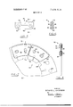
- FIG. 1 is an elevational view of a rotating disk of the brake assembly
- FIG. 2 is a sectional view taken along the line22 of FIG. 1;
- FIG. 3 is a side elevational view of one of the segments making up the disk of FIG. I;
- FIG. 4 is a sectional view taken along the line 4-4 of FIG. 3;
- FIG. 5 is a side elevational view of one of the clips employed to secure the segments of the disk of. FIG. 1;
- FIG. 6 is a sectional view taken along the line 6-6of FIG. 5;
- FIG. 7 is a fragmentary side elevationalview of one of the stationary disks of the brake assembly, with one of the sintered friction pads removed toshow the construction of the disk core; a
- FIG. 8 is a sectional view taken along the line 8-8 of FIG. 7;
- FIG. 9 is a fragmentary sectional view of the brake assembly employing the disks of the present invention.
- FIG. 10 is a fragmentary elevational view of a segmented stationary disk.
- FIG. 11 is a sectional view taken along the line 1 1- l 1 of FIG. 10.
- the rotating disk designated generally by the reference numeral 10, is formed of a number of identical segments 12.
- Clips 14 span the adjacent ends of each of the segments l2 and secure the-segments together by means of rivets 16.
- Each of the segments 12 is formed of a friction material and has parallel opposite wear faces 18. It is contemplated that the segments may be formed by a precision punching operation to reduce the amount of machining of each segment and to reduce the production costs.
- the radially outer and inner edges 20 and 22, respectively, of each segment 12 are of concentric configuration.
- the ends of the segments are of V- shaped configurations. A typical end configuration is illustrated in FIG. 3 when the right end of the segment 12 has a radial inner straight portion 24 which is curved edge 22 of the segment 12 atthe point of intersection of the straight portion 24 and the inner edge 22.
- the radially outer straight portion 26 of the segment end extends at a 75 angle to the inner portion 24.
- the opposite end of the segment is provided with complementary portions 28 and 30.
- At the radially outer ends of the segment there are provided ears 32 and 34 which, as can be seen from FIG. 4, are of reduced thickness and which project above the outer edge 20 of the segment 12.
- Holes 36 and 38 are provided in the cars 32 and 34, respectively. It should be noted that this arrangement permits the main portion of the segment 12 to be formed as a single mass of uniform thickness. This contributes to the strength of the segment, giving it greater resistance to distortion.
- the solid main portion of the segment also possesses a high heat sink capability.
- Each clip has spaced parallel side portions 40 which are joined by end portions 42 to provide a slot 44 in which the ears 32 or 34 of the disk segments 12 are received.
- the side portions 40 of the clips or links 14 are notched at 46 to provide drive notches for the disk assembly.
- Counter sunk holes 48 are provided at opposite ends of the side members 40 to receive the rivets 16 which secure the clips 14 to the ears 32 and 34 of the disks 12.
- the clips or links 14 hold the adjacent ends of the disk segments 12 a short distance from one another. This arrangement allows for thermal expansion of the disks without distortion.
- the complementary edges 24, 28 and 26, 30 of the adjacent ends of the segments 12 serve to properly align the adjacent segments and to prevent the segments from twisting out of the true concentric position, thus eliminating the undesirable saw toothing condition.
- FIGS. 7 and 8 The construction of a stationary disk of the brake assembly is shown in FIGS. 7 and 8.
- the stationary disk designated generally by the reference numeral 50, has a steel backing plate 52 in the form of an annular ring with notches 54 on its inner circumference for engaging the splines of the housing.
- Friction wear pads 56 are carried in cup-like members 58 which are secured by rivets 60 passing through holes 62 in the backing plates 52.
- the construction of the backing and pressure plates of the brake assembly is similar, wear pads being riveted to only one face of each of these plates, however.
- each segment 86 has a steel core plate 88 and friction pads 90 bonded to the opposite faces thereof.
- the core plate 90 extends radially inwardly beyond the pads 90, as indicated at 92, and is provided with a notch 94 for engaging a spline of the fixed brake housing.
- the ends of each segment 86 are of a generally V-shaped configuration. This can be seen in FIG. 10 where the radially inner portion 95 of one end of the segment 86 is parallel to the radius from the center of the disk 84 to the radially inner end of the portion 92 of the core 88.
- the intermediate portion 96 of this end of the segment 86 which is the radially inner portion of the friction pad 90, is inclined at a 1 75 angle to the inner portion 95.
- the radially outer portion 98 of this end extends at a angle to the intermediate portion 96.
- the corresponding portions 99,100, and 102 of the opposite end of each segment 86 are of com plementary configuration so as to be parallel to the portions 95, 96, and 98, respectively, of the end of the adjacent segment. It should be noted that the V-shaped ends of the segments 86 of the stationary disk 84 face in the opposite direction relative to the ends of the segments 12 of the rotating disk 10. This assures a smooth transition of the segments 12 across the segments 86 to reduce vibration, noise, and wear of the brake disks.
- the individual segments 86 are joined to one another to form the stationary disk 84 by means of links 104.
- These short links 104 span the ends of adjacent disk segments 86 on either side of the segments and are held in place by rivets 106 which pass through holes 108 in the links 104 and, through holes 110 in the inner portions 92 of the segment core plates 88.
- Bushings or sleeves 112 are provided in the holes 110.
- the brake assembly is shown somewhat schematically in FIG. 9.
- a housing 64 is secured to a fixed axle 66.
- This housing has an end plate 68 at one end, a second end plate 70 at the opposite end, and a series of splines 72 extending axially between the end plates.
- a rotating wheel assembly 74 is carried on the fixed axle 66 by suitable bearings, not shown.
- a series of axially extending splines 76 are provided on the inner circumference of the wheel assembly 74.
- the housing end v70 is provided with a piston arrangement 78.
- Alternate ones of the rotating disks 10 and stationary disks 50 or 84 are carried between the housing ends 68 and 70 with the drive notches of the rotating disks l0 engaging the splines 76 of the rotating wheel while the drive notches of the stationary disks 50 or 84 engage the splines 72 of the fixed housing.
- a pressure plate 80 is provided between the pistons 78 and the first disk of the series. This plate 80 is axially movable between the housing ends 68 and 70 and is provided with notches which engage the spline 72 of the fixed housing 64.
- a backing plate 82 is provided on the rear end 68 of the housing 64. Braking action is achieved by forcing the pressure plate 80 axially toward the second end 68 of the housing 64 to apply clamping pressure to the series of rotating and stationary disks.
- the brake assembly may be of conventional construction.
- the improved disks of the present invention may readily be retrofitted to existing brake units to improve the capability and durability of such units.
- a brake disk for use in a brake assembly of the type having a number of alternate rotating and stationary disks carried between and axially movable between a backing plate and a pressure plate, comprisa plurality of identical arcuate segments formed of a friction material and together forming an annular disk, each segment having circumferentially spaced ends and radially spaced sides with substantially the entire faces of the adjacent ends of the segments being of complementary V-shaped configuration;
- links being arranged on one circumference of the disk and outside the rubbing area of the disk, each link spanning the ends of adjacent disks;
- each segment has a radially inner portion which extends at a 60 angle to the tangent to the inner curved edge of the segment at the point of intersection of the inner curved edge and the radially inner portion of the first end and a radially outer portion extending at a 75 angle to the inner portion.
- each segment has ear portions at its first and second ends, the ear portions being of lesser thickness than the remainder of the segment and extending beyond one of the arcuate edges of the segment each link extending over and secured to the ear portions of adjacent ends of adjacent segments.
- each link has a pair of parallel side members spaced from one another by the thickness of the ear portions of the segments, the combined thicknesses of the side members and the ear portion being substantially equal to the thickness of the body portion of the segment.
- a brake assembly comprising an axle, a housing secured to the axle, a first set of disks keyed to the housing for axial movement a wheel rotatably mounted on the axle, a second set of annular disks keyed to the wheel for axial movement, the disks of the first and second sets being in an interleaved arrangement, a backing plate secured to the housing at one end of the sets of disks, a pressure plate at the opposite end of the sets of disks keyed to the housing for axial movement, and means to apply 'an axially directed force to the pressure plate to effect axial movement thereof toward the disks; the assembly being characterized in.
- each disk of one of the sets of disks is comprised of:
- each segment having circumferentially spaced ends and radially spaced sides with substantially the entire faces of the adjacent ends of the segments being of complementary V-shaped configuration;
- each link being arranged on one circumference of the disk and outside the rubbing surface of the disk, each link connecting two adjacent segments across their ends to form an annular disk and incorporating means for keying the disk to the respective one of the wheel and axle.
- each disk of the other set of disks comprises an annular core plate and a plurality of wear faces secured to each side of the core plate.
- the one set of disks comprise the second set of disks, the clips being located at the outer circumference of the disks and including notches for engaging the keys of the wheel, and the other set of disks comprise the first set of disks, the core plates being provided with notches on their inner circumferences to engage the keys of the housing.
- each disk of the other set of disks is comprised of a plurality of identical arcuate segments, each segment having a steel core plate and friction pads secured to the opposite faces of the core plate, a plurality of links spanning adjacent segments, and means securing the links to the segments.
- the other set of disks comprises the first set of disks, the core plates of the segments extending radially inward beyond the friction pads, and the core plates having notches on the inner circumferences thereof for engaging the keys of the housing.
Landscapes
- Engineering & Computer Science (AREA)
- General Engineering & Computer Science (AREA)
- Mechanical Engineering (AREA)
- Braking Arrangements (AREA)
Applications Claiming Priority (1)
| Application Number | Priority Date | Filing Date | Title |
|---|---|---|---|
| US10103370A | 1970-12-23 | 1970-12-23 |
Publications (1)
| Publication Number | Publication Date |
|---|---|
| US3698519A true US3698519A (en) | 1972-10-17 |
Family
ID=22282783
Family Applications (1)
| Application Number | Title | Priority Date | Filing Date |
|---|---|---|---|
| US101033A Expired - Lifetime US3698519A (en) | 1970-12-23 | 1970-12-23 | Articulated disc brake configurations |
Country Status (12)
| Country | Link |
|---|---|
| US (1) | US3698519A (fr) |
| JP (1) | JPS5417386B1 (fr) |
| AU (1) | AU441960B2 (fr) |
| BE (1) | BE776743A (fr) |
| CA (1) | CA949466A (fr) |
| CH (1) | CH543686A (fr) |
| DE (1) | DE2164418C3 (fr) |
| FR (1) | FR2119410A5 (fr) |
| GB (1) | GB1344119A (fr) |
| IT (1) | IT945391B (fr) |
| NL (1) | NL7117300A (fr) |
| SE (1) | SE374181B (fr) |
Cited By (13)
| Publication number | Priority date | Publication date | Assignee | Title |
|---|---|---|---|---|
| US3804213A (en) * | 1971-07-02 | 1974-04-16 | Messier Hispano Sa | Disc-brake with heat-sink using graphite |
| US3885659A (en) * | 1973-09-24 | 1975-05-27 | Goodrich Co B F | Segmental friction member for brake or clutch |
| US3902578A (en) * | 1973-10-05 | 1975-09-02 | Goodyear Aerospace Corp | Segmented friction disk for brake or clutch |
| US3904000A (en) * | 1974-01-16 | 1975-09-09 | Goodyear Aerospace Corp | Segmented brake disk |
| US3907076A (en) * | 1971-05-24 | 1975-09-23 | Goodyear Aerospace Corp | Key slot segments for driving brake discs |
| US4155432A (en) * | 1977-08-24 | 1979-05-22 | Goodyear Aerospace Corporation | Rigid segmented brake disk |
| US4747473A (en) * | 1986-06-19 | 1988-05-31 | The B. F. Goodrich Company | Segmented friction brake or clutch disc assembly |
| US5620063A (en) * | 1994-11-02 | 1997-04-15 | Alcon Components Limited | Three section pad in caliper disc brakes |
| US6062348A (en) * | 1997-12-04 | 2000-05-16 | Atkinson, Jr.; John H. | Rapidly-deployable vehicle snow chain system having individually-replaceable interlocking chain attachment plates |
| US20060185945A1 (en) * | 2005-02-23 | 2006-08-24 | Bruno Greppi | Brake for vehicle wheels that is provided with a braking disc in sectors |
| US7159698B2 (en) | 2004-07-22 | 2007-01-09 | Bendix Spicer Foundation Brake, Llc | Disc brake rotor assembly with replaceable wear surfaces |
| US20080135359A1 (en) * | 2006-12-11 | 2008-06-12 | Basirico John T | Brake rotor with ceramic matrix composite friction surface plates |
| CN116281708A (zh) * | 2023-03-28 | 2023-06-23 | 广西壮族自治区特种设备检验研究院 | 一种微椭圆弹性变形的曳引式电梯制动器 |
Families Citing this family (2)
| Publication number | Priority date | Publication date | Assignee | Title |
|---|---|---|---|---|
| DE202009013476U1 (de) * | 2009-10-06 | 2011-02-17 | Faiveley Transport Witten Gmbh | Bremsscheibe |
| DE102015224263A1 (de) * | 2015-12-04 | 2017-06-08 | Schaeffler Technologies AG & Co. KG | Stahllamelle für eine Lamellenkupplung |
Citations (6)
| Publication number | Priority date | Publication date | Assignee | Title |
|---|---|---|---|---|
| US2247298A (en) * | 1937-09-29 | 1941-06-24 | Kattwinkel Hans | Multiple disk brake, coupling, and the like |
| US2423882A (en) * | 1942-08-06 | 1947-07-15 | Bendix Aviat Corp | Disk brake |
| US3422936A (en) * | 1966-05-05 | 1969-01-21 | Hispano Suiza Lallemant Soc | Sector type friction brake disc |
| US3452844A (en) * | 1966-10-06 | 1969-07-01 | Hispano Suiza Lallemant Soc | Segmented brake disc |
| US3456768A (en) * | 1967-11-20 | 1969-07-22 | Bendix Corp | Disc element construction for disc brake |
| US3550740A (en) * | 1968-05-03 | 1970-12-29 | Goodrich Co B F | Segmented friction member for brake or clutch |
Family Cites Families (4)
| Publication number | Priority date | Publication date | Assignee | Title |
|---|---|---|---|---|
| DE674759C (de) * | 1937-09-30 | 1939-04-21 | Hans Kattwinkel | Blechlamelle fuer Mehrscheibenbremsen und -kupplungen |
| FR895135A (fr) * | 1941-02-27 | 1945-01-16 | Kattwinkel | Lamelles de friction pour freins et embrayages à lames |
| GB579172A (en) * | 1942-07-04 | 1946-07-25 | Bendix Aviat Corp | Improvements in or relating to disk brakes |
| GB1246158A (en) * | 1968-06-25 | 1971-09-15 | Goodyear Tire & Rubber | Improvements in multi-disc brakes |
-
1970
- 1970-12-23 US US101033A patent/US3698519A/en not_active Expired - Lifetime
-
1971
- 1971-11-22 GB GB5442171A patent/GB1344119A/en not_active Expired
- 1971-11-26 AU AU36190/71A patent/AU441960B2/en not_active Expired
- 1971-11-26 CA CA128,617A patent/CA949466A/en not_active Expired
- 1971-12-11 IT IT54685/71A patent/IT945391B/it active
- 1971-12-14 FR FR7144871A patent/FR2119410A5/fr not_active Expired
- 1971-12-14 JP JP10073471A patent/JPS5417386B1/ja active Pending
- 1971-12-15 BE BE776743A patent/BE776743A/fr unknown
- 1971-12-16 NL NL7117300A patent/NL7117300A/xx unknown
- 1971-12-20 SE SE7116325A patent/SE374181B/xx unknown
- 1971-12-20 CH CH1857271A patent/CH543686A/fr not_active IP Right Cessation
- 1971-12-22 DE DE2164418A patent/DE2164418C3/de not_active Expired
Patent Citations (6)
| Publication number | Priority date | Publication date | Assignee | Title |
|---|---|---|---|---|
| US2247298A (en) * | 1937-09-29 | 1941-06-24 | Kattwinkel Hans | Multiple disk brake, coupling, and the like |
| US2423882A (en) * | 1942-08-06 | 1947-07-15 | Bendix Aviat Corp | Disk brake |
| US3422936A (en) * | 1966-05-05 | 1969-01-21 | Hispano Suiza Lallemant Soc | Sector type friction brake disc |
| US3452844A (en) * | 1966-10-06 | 1969-07-01 | Hispano Suiza Lallemant Soc | Segmented brake disc |
| US3456768A (en) * | 1967-11-20 | 1969-07-22 | Bendix Corp | Disc element construction for disc brake |
| US3550740A (en) * | 1968-05-03 | 1970-12-29 | Goodrich Co B F | Segmented friction member for brake or clutch |
Cited By (14)
| Publication number | Priority date | Publication date | Assignee | Title |
|---|---|---|---|---|
| US3907076A (en) * | 1971-05-24 | 1975-09-23 | Goodyear Aerospace Corp | Key slot segments for driving brake discs |
| US3804213A (en) * | 1971-07-02 | 1974-04-16 | Messier Hispano Sa | Disc-brake with heat-sink using graphite |
| US3885659A (en) * | 1973-09-24 | 1975-05-27 | Goodrich Co B F | Segmental friction member for brake or clutch |
| US3902578A (en) * | 1973-10-05 | 1975-09-02 | Goodyear Aerospace Corp | Segmented friction disk for brake or clutch |
| US3904000A (en) * | 1974-01-16 | 1975-09-09 | Goodyear Aerospace Corp | Segmented brake disk |
| US4155432A (en) * | 1977-08-24 | 1979-05-22 | Goodyear Aerospace Corporation | Rigid segmented brake disk |
| US4747473A (en) * | 1986-06-19 | 1988-05-31 | The B. F. Goodrich Company | Segmented friction brake or clutch disc assembly |
| US5620063A (en) * | 1994-11-02 | 1997-04-15 | Alcon Components Limited | Three section pad in caliper disc brakes |
| US6062348A (en) * | 1997-12-04 | 2000-05-16 | Atkinson, Jr.; John H. | Rapidly-deployable vehicle snow chain system having individually-replaceable interlocking chain attachment plates |
| US7159698B2 (en) | 2004-07-22 | 2007-01-09 | Bendix Spicer Foundation Brake, Llc | Disc brake rotor assembly with replaceable wear surfaces |
| US20060185945A1 (en) * | 2005-02-23 | 2006-08-24 | Bruno Greppi | Brake for vehicle wheels that is provided with a braking disc in sectors |
| US20080135359A1 (en) * | 2006-12-11 | 2008-06-12 | Basirico John T | Brake rotor with ceramic matrix composite friction surface plates |
| CN116281708A (zh) * | 2023-03-28 | 2023-06-23 | 广西壮族自治区特种设备检验研究院 | 一种微椭圆弹性变形的曳引式电梯制动器 |
| CN116281708B (zh) * | 2023-03-28 | 2023-12-05 | 广西壮族自治区特种设备检验研究院 | 一种微椭圆弹性变形的曳引式电梯制动器 |
Also Published As
| Publication number | Publication date |
|---|---|
| SE374181B (fr) | 1975-02-24 |
| GB1344119A (en) | 1974-01-16 |
| BE776743A (fr) | 1972-04-04 |
| CA949466A (en) | 1974-06-18 |
| DE2164418C3 (de) | 1982-01-07 |
| FR2119410A5 (fr) | 1972-08-04 |
| DE2164418B2 (de) | 1981-05-07 |
| DE2164418A1 (de) | 1972-07-13 |
| AU441960B2 (en) | 1973-11-08 |
| IT945391B (it) | 1973-05-10 |
| JPS5417386B1 (fr) | 1979-06-29 |
| NL7117300A (fr) | 1972-06-27 |
| AU3619071A (en) | 1973-05-31 |
| CH543686A (fr) | 1973-10-31 |
Similar Documents
| Publication | Publication Date | Title |
|---|---|---|
| US3698519A (en) | Articulated disc brake configurations | |
| US3757907A (en) | Key slot segments for driving brake discs | |
| US4865160A (en) | Dual disk brake | |
| US3623579A (en) | Fabricated rotor for a disk brake assembly | |
| US4177883A (en) | Discs for disc brakes | |
| US3613851A (en) | Segmented friction member for brake or clutch | |
| US3907076A (en) | Key slot segments for driving brake discs | |
| US8336682B2 (en) | Ventilated brake disk and method | |
| US3425524A (en) | Brake disc structure | |
| US3750788A (en) | Clutch or brake | |
| US3904000A (en) | Segmented brake disk | |
| US3895693A (en) | Disc-brakes with graphite friction linings | |
| WO2020103282A1 (fr) | Disque de frein monté sur essieu entièrement en carbone-céramique | |
| US3605968A (en) | Segmented friction member for brake or clutch | |
| US2794526A (en) | Clutch device | |
| US3917043A (en) | Friction disc member for brake or clutch | |
| US3759354A (en) | Brake disc structure | |
| US6340075B1 (en) | Three run disk brake stack and method of assembly | |
| US3885659A (en) | Segmental friction member for brake or clutch | |
| US3483953A (en) | Disc element construction for disc brake | |
| US3498418A (en) | Multi-plate disc brake and disc spacing means | |
| US3599766A (en) | Segmented friction member for brake or clutch | |
| US3726374A (en) | Circular segmented friction member for brake or clutch | |
| US2255023A (en) | Brake disk assembly | |
| US3746139A (en) | Friction disc member for brake or clutch |
Legal Events
| Date | Code | Title | Description |
|---|---|---|---|
| AS | Assignment |
Owner name: LORAL CORPORATION, 600 THIRD AVENUE, NEW YORK, NEW Free format text: ASSIGNMENT OF ASSIGNORS INTEREST.;ASSIGNOR:GOODYEAR TIRE & RUBBER COMPANY, THE;REEL/FRAME:004869/0150 Effective date: 19880209 Owner name: LORAL CORPORATION,NEW YORK Free format text: ASSIGNMENT OF ASSIGNORS INTEREST;ASSIGNOR:GOODYEAR TIRE & RUBBER COMPANY, THE;REEL/FRAME:004869/0150 Effective date: 19880209 |
|
| AS | Assignment |
Owner name: MANUFACTURERS HANOVER TRUST COMPANY, AS AGENT Free format text: SECURITY INTEREST;ASSIGNOR:AIRCRAFT BRAKING CORPORATION;REEL/FRAME:005164/0047 Effective date: 19890427 |
|
| AS | Assignment |
Owner name: MANUFACTURERS HANOVER TRUST COMPANY, AS AGENT Free format text: SECURITY INTEREST;ASSIGNOR:AIRCRAFT BRAKING CORPORATION, A CORP. OF DE;REEL/FRAME:005249/0786 Effective date: 19890427 |