US3700910A - Bragg angle optical matched filter system with coded glass transmission plate - Google Patents
Bragg angle optical matched filter system with coded glass transmission plate Download PDFInfo
- Publication number
- US3700910A US3700910A US64908A US3700910DA US3700910A US 3700910 A US3700910 A US 3700910A US 64908 A US64908 A US 64908A US 3700910D A US3700910D A US 3700910DA US 3700910 A US3700910 A US 3700910A
- Authority
- US
- United States
- Prior art keywords
- light
- matched filter
- phase front
- order
- coded
- Prior art date
- Legal status (The legal status is an assumption and is not a legal conclusion. Google has not performed a legal analysis and makes no representation as to the accuracy of the status listed.)
- Expired - Lifetime
Links
Images
Classifications
-
- G—PHYSICS
- G02—OPTICS
- G02F—OPTICAL DEVICES OR ARRANGEMENTS FOR THE CONTROL OF LIGHT BY MODIFICATION OF THE OPTICAL PROPERTIES OF THE MEDIA OF THE ELEMENTS INVOLVED THEREIN; NON-LINEAR OPTICS; FREQUENCY-CHANGING OF LIGHT; OPTICAL LOGIC ELEMENTS; OPTICAL ANALOGUE/DIGITAL CONVERTERS
- G02F1/00—Devices or arrangements for the control of the intensity, colour, phase, polarisation or direction of light arriving from an independent light source, e.g. switching, gating or modulating; Non-linear optics
- G02F1/01—Devices or arrangements for the control of the intensity, colour, phase, polarisation or direction of light arriving from an independent light source, e.g. switching, gating or modulating; Non-linear optics for the control of the intensity, phase, polarisation or colour
- G02F1/11—Devices or arrangements for the control of the intensity, colour, phase, polarisation or direction of light arriving from an independent light source, e.g. switching, gating or modulating; Non-linear optics for the control of the intensity, phase, polarisation or colour based on acousto-optical elements, e.g. using variable diffraction by sound or like mechanical waves
-
- G—PHYSICS
- G01—MEASURING; TESTING
- G01S—RADIO DIRECTION-FINDING; RADIO NAVIGATION; DETERMINING DISTANCE OR VELOCITY BY USE OF RADIO WAVES; LOCATING OR PRESENCE-DETECTING BY USE OF THE REFLECTION OR RERADIATION OF RADIO WAVES; ANALOGOUS ARRANGEMENTS USING OTHER WAVES
- G01S13/00—Systems using the reflection or reradiation of radio waves, e.g. radar systems; Analogous systems using reflection or reradiation of waves whose nature or wavelength is irrelevant or unspecified
- G01S13/02—Systems using reflection of radio waves, e.g. primary radar systems; Analogous systems
- G01S13/06—Systems determining position data of a target
- G01S13/08—Systems for measuring distance only
- G01S13/10—Systems for measuring distance only using transmission of interrupted, pulse modulated waves
- G01S13/26—Systems for measuring distance only using transmission of interrupted, pulse modulated waves wherein the transmitted pulses use a frequency- or phase-modulated carrier wave
- G01S13/28—Systems for measuring distance only using transmission of interrupted, pulse modulated waves wherein the transmitted pulses use a frequency- or phase-modulated carrier wave with time compression of received pulses
- G01S13/284—Systems for measuring distance only using transmission of interrupted, pulse modulated waves wherein the transmitted pulses use a frequency- or phase-modulated carrier wave with time compression of received pulses using coded pulses
- G01S13/288—Systems for measuring distance only using transmission of interrupted, pulse modulated waves wherein the transmitted pulses use a frequency- or phase-modulated carrier wave with time compression of received pulses using coded pulses phase modulated
Definitions
- first order 34245l2 1/1969 gi 6/71X plane phase from is produced.
- An analyzer blocks 3585392 6/1971 2 "5 X most of the zero order light to reduce the bias on a 3435244 3/1969 356/71 X photomultiplier.
- the first order plane phase front is 3365579 1/1968 r s g 8 5 X focused to a spot by a transform lens and the light is 3395960 8/1968 Chan et a! 350/150 passed through an optimized aperture or slit to the g photomultiplier where the optical output is converted to an electrical output.
- the present invention relates generally to improvements in pulse radar, and more particularly it pertains to a new and improved Bragg Angle optical matched filter with a coded glass transmission plate.
- the matched filter which is designed for a specific signal, is not designed to give an output that faithfully reproduces the input signal. The matched filter, however, optimizes detection, providing the best peak signal-to-noise ratio.
- optical materials currently being used in Bragg Angle matched filters used at high frequencies is such that the zero order and first order frequency components can be easily separated. However, at lower frequencies there is smaller angular separation between the zero and first orders and the high frequency techniques are not as useful.
- the zero order creates an undesired bias on the light detector.
- Complicated schemes utilizing lenses and stops have been used to reduce or eliminate the zero order at lower frequencies.
- Another object is to provide an optical matched filter system which is simpler, requires less space and is cheaper to manufacture.
- a further object of the invention is to increase the range when the filter is used in a peak-power-limited radar using a phase-coded pulse instead of a convention rectangular pulse.
- Still another object is to optimize detection and to increase the signal-to-noise ratio of a signal.
- a still further object is to provide a simple in-line system compared to the more complex folded system where a coded mirror is used.
- the general purpose of this invention is to improve and extend radar range performance through pulse coding.
- the Bragg Angle optical matched filter system of the present invention was developed having a pulse compression of 100:1 (l0 microsecond pulse compressed to 0.1 microsecond pulse) when a binary phase coded electrical pulse is put into the system. Pulse compression allows a wider pulse and, thus, more energy can be transmitted for a given range resolution which results in an increase in the signal-to-noise ratio.
- the matched filter of the present invention replaces the detector in a radar system and can be tailored to provide radar target parameters by optimizing the signal form.
- the drawing is a schematic, partially in block dia- DESCRIPTION OF THE PREFERRED EMBODIMENT
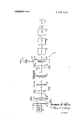
- the drawing which illustrates a preferred embodiment of the present invention, shows the optical matched filter system 10 and its various components now to be described.
- the light source used in this system is a Spectra- Physics model 124 helium-neon gas laser 12 which produces a 1.1MM diameter zero order light beam at a wave length of 6328 A.
- a collimating lens 14 is used with a spatial filter 16 to produce a spatial filtered collimated beam from the output of laser 12. Spatial filtering is accomplished by focusing of the beam through an exit aperture of laser 12 which is close to the diffraction-limited spot size for the focusing lens. Collimation of the filtered light is accomplished by placing the focused spot at the focal point of the collimating lens 14. Beam expansion is dependent on the ratio of the equivalent focal lengths of the two lens systems used in the collimating lens 14 and the spatial filter 16. For the values used, the input laser beam of diameter 1.1MM is expanded to 12.1MM. The laser beam is expanded for more efficient use of the prism expanding beam optics to be described.
- a beam spreading prism system 18 is used to spread out the laser light beam in one dimension so that it can interact over the entire length of an acoustic signal in the ultrasonic light modulator 20 to be described (approximately 15 inches).
- the laser beam which impinges the prism system 18 is spread to about 30 times the original width.
- the beam is spread so that the flatter portion of the intensity profile illuminates a coded signal in the ultrasonic or acoustic modulator 20.
- the output beam width is limited by a stop (not shown) to correspond to the signal length in the modulator 20.
- the prisms are 8MM thick. On one side they have an anti-reflection coating for an angle of incidence of from the normal. Reflection is less than 1% for light polarized parallel to the plane of incidence. The exit side of the prisms have an anti-reflection coating for normal incidence.
- a M2 wave plate attached to the collimating lens 14 is used to rotate the polarization of light for minimum reflection.
- the fused Silica acoustic or ultrasonic light modulator and amplifier shown in the drawing operates in the shear mode producing first order light polarized orthogonal to the zero order light from the laser 12 in either a Debye-Sears or Bragg diffraction mode.
- An electrical phase coded pulse 22 is converted by appropriate'transducers 24 into an acoustic shear wave signal 26 which is propagated through the acoustic modulator 20 and modulates the laser light beam.
- the acoustic beam is either oriented perpendicular or at the Bragg angle to interact with the light beam to produce beam directions related to the angular frequencies of the light and acoustic waves.
- the acoustic energy generates first order light containing a coded phase from 28 polarized orthogonal to the zero order light which contains a plane phase front 30.
- the type of diffraction mode is dependent on the orientation of the modulator 20 to the laser light beam and on the frequency of the acoustical signal 26.
- a binary coded transmission phase plate 32 is constructed using the glass on glass method.
- the plate 32 may be provided with several codes which can be selected by moving the coded phase plate 32 relative to the light beam to match the code placed on the light beam by the acoustic modulator 20. If the two are matched when the light beam or first order coded phase front impinges on the coded transmission plate, a first order plane phase front 34 emerges having maximum light.
- An analyzer 36 is used in the system to block most of the zero order light and thus reduce the bias on a photomultiplier 42.
- the analyzer is a polarized absorption type with unknown flatness. The amount that linear polarized light beam is attenuated depends on the orientation of the analyzer 36 to the light beam. When oriented properly the analyzer 36 discriminates between the first order optical signal 28 and the orthogonally polarized zero order signal 30. it discriminates between the two polarizations and attenuates the undesired zero order signal 30.
- the only lens system used in this matched filter is the transforming lens 38 used to provide the transform of a spatial signal.
- the first order plane phase front 34 is focused to a spot by the transform lens 38.
- a stop with a photomultiplier slit 40 is also used in the in-line system of the present invention and has a variable width slit which is generated through photographic reduction, resulting in a negative on a high resolution Kodak plate.
- the glass plate is then cut to fit into a cartridge.
- Cartridges with different slit designs can be easily fitted to the face of a photomultiplier 42. This makes possible easy introduction of different slits into the optical system.
- the light from the transform lens 38 is passed through slit 40 to the photomultiplier 42.
- the ten-stage head-on type RCA photomultiplier and amplifier 42 converts the systems optical output to an electrical output.
- the photomultipliers output signal is then fed into a high impedance unity gain Textronics probe (not shown).
- the probe converts the high impedance signal into a signal matched to a 50 ohm line without loss of gain. This enables the signal to be handled in a 50 ohm system.
- the ultrasonic light modulator 20 operates in the Debye-Sears or Bragg mode depends on the parameters of the transducer 24 and the frequency range of the acoustic signals 26.
- the acoustic modulator 20 used in this system can operate in either mode.
- the acoustic waves are of the shear type.
- the linearly polarized incident light is oriented to produce firstorder polarized light rotated from the incident.
- phase coded mirror could be used instead of the phase coded transmission plate 32.
- optical code generator could be used instead of the electrical code generator to provide for an overall more simplified system.
- An optical matched filter system comprising:
- a coded glass transmission plate means for producing a first order plane phase front from said first order coded front
- polarized absorption type analyzer means to substantially block the passage of said zero order light
- a transform lens means to focus only said first order plane phase front through an aperture and onto a photomultiplier.
- ultrasonic light modulator means comprises a transducer to produce an acoustic shear wave signal which is propogated through fused silica.
- An optical matched filter system for use in a pulse radar system comprising:
- third means situated along said axis for intercepting said zero order light and generating a first order coded phase front polarized orthogonal to said zero order light;
Landscapes
- Physics & Mathematics (AREA)
- Engineering & Computer Science (AREA)
- Radar, Positioning & Navigation (AREA)
- Remote Sensing (AREA)
- Nonlinear Science (AREA)
- General Physics & Mathematics (AREA)
- Optics & Photonics (AREA)
- Computer Networks & Wireless Communication (AREA)
- Investigating Or Analysing Materials By Optical Means (AREA)
Abstract
The optical matched filter system provides a means of achieving pulse compression for pulse radar with an improved range resolution. The system separates zero and first order light at low frequencies (30-60MC region) by making use of the polarization properties of shear mode acoustic waves in quartz. Linear polarized collimated zero order light from a laser illuminates an acoustic modulator. An electrical signal is converted by transducers into an acoustic shear wave signal which is propagated through the acoustic modulator and modulates the laser light beam to generate first order light containing a coded phase front polarized orthogonal to the zero order light from the laser containing a plane phase front. When the first order coded phase front and a coded glass transmission plate are matched at the moment of correlation a first order plane phase front is produced. An analyzer blocks most of the zero order light to reduce the bias on a photomultiplier. The first order plane phase front is focused to a spot by a transform lens and the light is passed through an optimized aperture or slit to the photomultiplier where the optical output is converted to an electrical output.
Description
0 United States 1 3,700,910 Smith Oct. 24, 1972 [54] BRAGG ANGLE OPTICAL MATCI-IED OTHER PUBLICATIONS FILTER SYSTEM WITH CODED GLASS Geng et al: IEEE Proceedings; Vol. 52; No. 12; Dec. TRANSMISSION PLATE 1964; p. 1753. [72] Inventor: Richard M. Smith, China Lake,
Calif. Primary Examiner-Walter Stolwein [73] Assignee The United States of flea as Attorney-R. S. Sciascia and Thomas 0. Watson, Jr. rNegar-yesented by the Secretary of the [57] ABSTRACT [22] Filed Jul 23 1970 The optical matched filter system provides a means of y achieving pulse compression for pulse radar with an [21] Appl. No.: 64,908 improved range resolution. The system separates zero and first order light at low frequencies (30-60MC region) by making use of the polarization properties of [52] [1.8. CI. ..250/225, 250/216, 23355518419, Shear mode acoustic waves in quartz Linear polarized [51] Int Cl Gozf 1/18 collimated zero order light from a laser illuminates an [58] Fieid 356/71 acoustic modulator. An electrical signal is converted by transducers into an acoustic shear wave signal 356/149 350/150 324/77 235/181 which is propagated through the acoustic modulator and modulates the laser light beam to generate first [56] References Cited order light containing a coded phase front polarized UNITED STATES PATENTS orthogonal to the zero order light from the laser containing a plane phase front. When the first order i zg f jl g coded phase front and a coded glass transmission plate 3483386 12/1969 J gu 250/216 are matched at the moment of correlation a first order 34245l2 1/1969 gi 6/71X plane phase from is produced. An analyzer blocks 3585392 6/1971 2 "5 X most of the zero order light to reduce the bias on a 3435244 3/1969 356/71 X photomultiplier. The first order plane phase front is 3365579 1/1968 r s g 8 5 X focused to a spot by a transform lens and the light is 3395960 8/1968 Chan et a! 350/150 passed through an optimized aperture or slit to the g photomultiplier where the optical output is converted to an electrical output.
9 Claims, 1 Drawing Figure SIGNAL IN 51% FIRST ORDER 24 STOP WITH c0050 GLASS SLIT LENS FIRST ANALYZER TRANSMISSION FIRST 20 ORDER PLATE ORDER arr 1 P IER 9 I; w I PRISM -4I- FILTER 4 LENS LASER 42 I E3 l /2 40 32 3o 26 /8 l6 /4 ZERO ERO ZERO ORDER ORDER ORDER PATENTEDncI 24 I972 SIGNAL STOP WITH IRST ANALYZER O INVENTOR. RICHARD M. SM/ TH JAM 9. 005
ATTORNEY BRAGG ANGLE OPTICAL MATCHED FILTER SYSTEM WITH CODED GLASS TRANSMISSION PLATE STATEMENT OF GOVERNMENT INTEREST The invention described herein may be manufactured and used by or for the Government of the United States of America for governmental purposes without the payment of any royalities thereon or therefor.
BACKGROUND OF THE INVENTION The present invention relates generally to improvements in pulse radar, and more particularly it pertains to a new and improved Bragg Angle optical matched filter with a coded glass transmission plate.
A filter is considered to be a matched filter if the impulse function h(t) of the filter is the time inverse of the signal f(t). That is, if h(t)=f(-t). The matched filter, which is designed for a specific signal, is not designed to give an output that faithfully reproduces the input signal. The matched filter, however, optimizes detection, providing the best peak signal-to-noise ratio.
In the field of optical matched filters, it has been the general practice to employ electrical delay lines for achieving pulse compression, using biphase pulse coding, which is expensive and is subject to drift with changes in temperature. Also such devices have been unsatisfactory in that they are bulky and inconvenient. Recently other optical matched filters have been used, but they have several disadvantages. If the matched filters are to operate at a desirable low frequency (3060MC region) the required system is complex or uses expensive optics. Although some simpler matched filters have been developed they do not operate in the 3060MC region.
The nature of optical materials currently being used in Bragg Angle matched filters used at high frequencies is such that the zero order and first order frequency components can be easily separated. However, at lower frequencies there is smaller angular separation between the zero and first orders and the high frequency techniques are not as useful.
Also, the zero order creates an undesired bias on the light detector. Complicated schemes utilizing lenses and stops have been used to reduce or eliminate the zero order at lower frequencies.
OBJECTS OF THE INVENTION Accordingly, it is an object of the present invention to separate zero and first order light at low frequencies.
Another object is to provide an optical matched filter system which is simpler, requires less space and is cheaper to manufacture.
A further object of the invention is to increase the range when the filter is used in a peak-power-limited radar using a phase-coded pulse instead of a convention rectangular pulse.
Still another object is to optimize detection and to increase the signal-to-noise ratio of a signal.
A still further object is to provide a simple in-line system compared to the more complex folded system where a coded mirror is used.
Other objects, advantages and novel features of the invention will become apparent from the following detailed description of the invention when considered in conjunction with the accompanying drawings.
2 SUMMARY OF THE INVENTION The general purpose of this invention is to improve and extend radar range performance through pulse coding. To accomplish this the Bragg Angle optical matched filter system of the present invention was developed having a pulse compression of 100:1 (l0 microsecond pulse compressed to 0.1 microsecond pulse) when a binary phase coded electrical pulse is put into the system. Pulse compression allows a wider pulse and, thus, more energy can be transmitted for a given range resolution which results in an increase in the signal-to-noise ratio. The matched filter of the present invention replaces the detector in a radar system and can be tailored to provide radar target parameters by optimizing the signal form.
BRIEF DESCRIPTION OF THE DRAWING The drawing is a schematic, partially in block dia- DESCRIPTION OF THE PREFERRED EMBODIMENT The drawing, which illustrates a preferred embodiment of the present invention, shows the optical matched filter system 10 and its various components now to be described.
The light source used in this system is a Spectra- Physics model 124 helium-neon gas laser 12 which produces a 1.1MM diameter zero order light beam at a wave length of 6328 A. A collimating lens 14 is used with a spatial filter 16 to produce a spatial filtered collimated beam from the output of laser 12. Spatial filtering is accomplished by focusing of the beam through an exit aperture of laser 12 which is close to the diffraction-limited spot size for the focusing lens. Collimation of the filtered light is accomplished by placing the focused spot at the focal point of the collimating lens 14. Beam expansion is dependent on the ratio of the equivalent focal lengths of the two lens systems used in the collimating lens 14 and the spatial filter 16. For the values used, the input laser beam of diameter 1.1MM is expanded to 12.1MM. The laser beam is expanded for more efficient use of the prism expanding beam optics to be described.
A beam spreading prism system 18 is used to spread out the laser light beam in one dimension so that it can interact over the entire length of an acoustic signal in the ultrasonic light modulator 20 to be described (approximately 15 inches). The laser beam which impinges the prism system 18 is spread to about 30 times the original width. The beam is spread so that the flatter portion of the intensity profile illuminates a coded signal in the ultrasonic or acoustic modulator 20. The output beam width is limited by a stop (not shown) to correspond to the signal length in the modulator 20. The prisms are 8MM thick. On one side they have an anti-reflection coating for an angle of incidence of from the normal. Reflection is less than 1% for light polarized parallel to the plane of incidence. The exit side of the prisms have an anti-reflection coating for normal incidence. A M2 wave plate attached to the collimating lens 14 is used to rotate the polarization of light for minimum reflection.
The fused Silica acoustic or ultrasonic light modulator and amplifier shown in the drawing operates in the shear mode producing first order light polarized orthogonal to the zero order light from the laser 12 in either a Debye-Sears or Bragg diffraction mode. An electrical phase coded pulse 22 is converted by appropriate'transducers 24 into an acoustic shear wave signal 26 which is propagated through the acoustic modulator 20 and modulates the laser light beam. The acoustic beam is either oriented perpendicular or at the Bragg angle to interact with the light beam to produce beam directions related to the angular frequencies of the light and acoustic waves. The acoustic energy generates first order light containing a coded phase from 28 polarized orthogonal to the zero order light which contains a plane phase front 30. The type of diffraction mode is dependent on the orientation of the modulator 20 to the laser light beam and on the frequency of the acoustical signal 26.
A binary coded transmission phase plate 32 is constructed using the glass on glass method. The plate 32 may be provided with several codes which can be selected by moving the coded phase plate 32 relative to the light beam to match the code placed on the light beam by the acoustic modulator 20. If the two are matched when the light beam or first order coded phase front impinges on the coded transmission plate, a first order plane phase front 34 emerges having maximum light.
An analyzer 36 is used in the system to block most of the zero order light and thus reduce the bias on a photomultiplier 42. The analyzer is a polarized absorption type with unknown flatness. The amount that linear polarized light beam is attenuated depends on the orientation of the analyzer 36 to the light beam. When oriented properly the analyzer 36 discriminates between the first order optical signal 28 and the orthogonally polarized zero order signal 30. it discriminates between the two polarizations and attenuates the undesired zero order signal 30.
Aside from the collimating lens system 14, the only lens system used in this matched filter is the transforming lens 38 used to provide the transform of a spatial signal. The first order plane phase front 34 is focused to a spot by the transform lens 38.
A stop with a photomultiplier slit 40 is also used in the in-line system of the present invention and has a variable width slit which is generated through photographic reduction, resulting in a negative on a high resolution Kodak plate. The glass plate is then cut to fit into a cartridge. Cartridges with different slit designs can be easily fitted to the face of a photomultiplier 42. This makes possible easy introduction of different slits into the optical system. The light from the transform lens 38 is passed through slit 40 to the photomultiplier 42.
The ten-stage head-on type RCA photomultiplier and amplifier 42 converts the systems optical output to an electrical output. The photomultipliers output signal is then fed into a high impedance unity gain Textronics probe (not shown). The probe converts the high impedance signal into a signal matched to a 50 ohm line without loss of gain. This enables the signal to be handled in a 50 ohm system.
Whether the ultrasonic light modulator 20 operates in the Debye-Sears or Bragg mode depends on the parameters of the transducer 24 and the frequency range of the acoustic signals 26. The acoustic modulator 20 used in this system can operate in either mode. The acoustic waves are of the shear type. As used in the optical system of the present invention, the linearly polarized incident light is oriented to produce firstorder polarized light rotated from the incident.
Obviously many other modifications and variations of the present invention are possible. For example, a binary phase coded mirror could be used instead of the phase coded transmission plate 32. Also, an optical code generator could be used instead of the electrical code generator to provide for an overall more simplified system.
Obviously many modifications and variations of the present invention are possible in the light of the above teachings.
What is claimed is:
1. An optical matched filter system comprising:
a source of linear polarized collimated zero order light having a frequency in the range of 30-60 mc.;
a first means for generating a first order coded phase front polarized orthogonal to said zero order light when said zero order light impinges on said first means;
a coded glass transmission plate means for producing a first order plane phase front from said first order coded front;
polarized absorption type analyzer means to substantially block the passage of said zero order light, and;
a transform lens means to focus only said first order plane phase front through an aperture and onto a photomultiplier.
2. An optical matched filter system as recited in claim 6, wherein said first means is comprised of an ultrasonic light modulator means for producing an acoustic shear wave signal.
3. An optical matched filter system as recited in claim 2, wherein said ultrasonic light modulator means comprises a transducer to produce an acoustic shear wave signal which is propogated through fused silica.
4. An optical matched filter system as recited in claim 3 wherein a beam spreading prism means spreads out said zero order light in one dimension so it can interact over the entire length of said ultrasonic light modulator means.
5. An optical matched filter system as recited in claim 4, wherein a collimating lens is used with a spatial filter to produce said collimated zero order light.
6. An optical matched filter system for use in a pulse radar system comprising:
first means for generating a linear polarized collimated zero order light having a frequency in the range of 30-60 mc. along a longitudinal axis;
second means situated along said axis to spread said zero order light in one dimension;
third means situated along said axis for intercepting said zero order light and generating a first order coded phase front polarized orthogonal to said zero order light;
fourth means to produce a first order plane phase front from said first order coded phase front;
6 fifth means to remove substantially all of said zero 8. The matched filter system of claim 7 wherein said order light from said first order plane phase front; fifth means Comprises;
and,
I a polarized absorption type analyzer. sixth means to focus said first order plane phase front 9 The matched filter System of claim 8 wherein Said through an aperture and onto a photomultiplier. 5
7. The matched filter system of claim 6 wherein said 'igg means compnses a coded glass transmlsslon third means comprises: p
' a shear mode ultrasonic modulator.
Claims (9)
1. An optical matched filter system comprising: a source of linear polarized collimated zero order light having a frequency in the range of 30-60 mc.; a first means for generating a first order coded phase front polarized orthogonal to said zero order light when said zero order light impinges on said first means; a coded glass transmission plate means for producing a first order plane phase front from said first order coded front; polarized absorption type analyzer means to substantially block the passage of said zero order light, and; a transform lens means to focus only said first order plane phase front through an aperture and onto a photomultiplier.
2. An optical matched filter system as recited in claim 6, wherein said first means is comprised of an ultrasonic light modulator means for producing an acoustic shear wave signal.
3. An optical matched filter system as recited in claim 2, wherein said ultrasonic light modulator means comprises a transducer to produce an acoustic shear wave signal which is propogated through fused silica.
4. An optical matched filter system as recited in claim 3 wherein a beam spreading prism means spreads out said zero order light in one dimension so it can interact over the entire length of said ultrasonic light modulator means.
5. An optical matched filter system as recited in claim 4, wherein a collimating lens is used with a spatial filter to produce said collimated zero order light.
6. An optical matched filter system for use in a pulse radar system comprising: first means for generating a linear polarized collimated zero order light having a frequency in the range of 30-60 mc. along a longitudinal axis; second means situated along said axis to spread said zero order light in one dimension; third means situated along said axis for intercepting said zero order light and generating a first order coded phase front polarized orthogonal to said zero order light; fourth means to produce a first order plane phase front from said first order coded phase front; fifth means to remove substantially all of said zero order light from said first order plane phase front; and, sixth means to focus said first order plane phase front through an aperture and onto a photomultiplier.
7. The matched filter system of claim 6 wherein said third means comprises: a shear mode ultrasonic modulator.
8. The matched filter system of claim 7 wherein said fifth means comprises: a polarized absorption type analyzer.
9. The matched filter system of claim 8 wherein said fourth means comprises a coded glass transmission plate.
Applications Claiming Priority (1)
| Application Number | Priority Date | Filing Date | Title |
|---|---|---|---|
| US6490870A | 1970-07-23 | 1970-07-23 |
Publications (1)
| Publication Number | Publication Date |
|---|---|
| US3700910A true US3700910A (en) | 1972-10-24 |
Family
ID=22059046
Family Applications (1)
| Application Number | Title | Priority Date | Filing Date |
|---|---|---|---|
| US64908A Expired - Lifetime US3700910A (en) | 1970-07-23 | 1970-07-23 | Bragg angle optical matched filter system with coded glass transmission plate |
Country Status (1)
| Country | Link |
|---|---|
| US (1) | US3700910A (en) |
Cited By (3)
| Publication number | Priority date | Publication date | Assignee | Title |
|---|---|---|---|---|
| US3934153A (en) * | 1975-01-10 | 1976-01-20 | Itek Corporation | Electro-optic system with expanded power range |
| US3943464A (en) * | 1972-04-29 | 1976-03-09 | United Technologies Corporation | Modulator for electrical signals processed in a laser-acoustic delay line |
| US20080155922A1 (en) * | 2006-12-29 | 2008-07-03 | Wolf David H | Panelized veneer with backer-to-backer locators |
Citations (8)
| Publication number | Priority date | Publication date | Assignee | Title |
|---|---|---|---|---|
| US3189746A (en) * | 1961-11-03 | 1965-06-15 | Lockheed Aircraft Corp | Expansion and compression of electronic pulses by optical correlation |
| US3220003A (en) * | 1962-09-25 | 1965-11-23 | Scope Inc | Detector for varying carrier frequency signals |
| US3365579A (en) * | 1965-04-01 | 1968-01-23 | Bell Telephone Labor Inc | Optical wave correlator with acoustical modulation |
| US3395960A (en) * | 1964-05-28 | 1968-08-06 | Ibm | Light modulator |
| US3424512A (en) * | 1964-04-27 | 1969-01-28 | Conductron Corp | Optical spatial filtering with enlarged frequency spectrum plane |
| US3435244A (en) * | 1966-05-05 | 1969-03-25 | Bell Telephone Labor Inc | Pattern recognition apparatus utilizing complex spatial filtering |
| US3483386A (en) * | 1967-12-04 | 1969-12-09 | Us Navy | Bragg angle matched filter for producing and recognizing coded pulses |
| US3585392A (en) * | 1968-03-25 | 1971-06-15 | Zenith Radio Corp | Phase-modulated light detection |
-
1970
- 1970-07-23 US US64908A patent/US3700910A/en not_active Expired - Lifetime
Patent Citations (8)
| Publication number | Priority date | Publication date | Assignee | Title |
|---|---|---|---|---|
| US3189746A (en) * | 1961-11-03 | 1965-06-15 | Lockheed Aircraft Corp | Expansion and compression of electronic pulses by optical correlation |
| US3220003A (en) * | 1962-09-25 | 1965-11-23 | Scope Inc | Detector for varying carrier frequency signals |
| US3424512A (en) * | 1964-04-27 | 1969-01-28 | Conductron Corp | Optical spatial filtering with enlarged frequency spectrum plane |
| US3395960A (en) * | 1964-05-28 | 1968-08-06 | Ibm | Light modulator |
| US3365579A (en) * | 1965-04-01 | 1968-01-23 | Bell Telephone Labor Inc | Optical wave correlator with acoustical modulation |
| US3435244A (en) * | 1966-05-05 | 1969-03-25 | Bell Telephone Labor Inc | Pattern recognition apparatus utilizing complex spatial filtering |
| US3483386A (en) * | 1967-12-04 | 1969-12-09 | Us Navy | Bragg angle matched filter for producing and recognizing coded pulses |
| US3585392A (en) * | 1968-03-25 | 1971-06-15 | Zenith Radio Corp | Phase-modulated light detection |
Non-Patent Citations (1)
| Title |
|---|
| Gerig et al: IEEE Proceedings; Vol. 52; No. 12; Dec. 1964; p. 1753. * |
Cited By (3)
| Publication number | Priority date | Publication date | Assignee | Title |
|---|---|---|---|---|
| US3943464A (en) * | 1972-04-29 | 1976-03-09 | United Technologies Corporation | Modulator for electrical signals processed in a laser-acoustic delay line |
| US3934153A (en) * | 1975-01-10 | 1976-01-20 | Itek Corporation | Electro-optic system with expanded power range |
| US20080155922A1 (en) * | 2006-12-29 | 2008-07-03 | Wolf David H | Panelized veneer with backer-to-backer locators |
Similar Documents
| Publication | Publication Date | Title |
|---|---|---|
| US5602677A (en) | Dispersive optical delay line and use thereof for the compression/expansion of laser pulses | |
| US3549239A (en) | Optical signal processor | |
| Donley et al. | Double-pass acousto-optic modulator system | |
| EP0170158B1 (en) | Fourier plane recursive optical filter | |
| US3189746A (en) | Expansion and compression of electronic pulses by optical correlation | |
| US5148323A (en) | Local reference beam generator | |
| JPH03505494A (en) | Multi-channel filter system | |
| CN109375230B (en) | High-precision laser echo frequency modulation system and method | |
| JPH0237565B2 (en) | ||
| US4390247A (en) | Continuously variable delay line | |
| US3719906A (en) | Dispersive delay lines operating in the shear mode | |
| US3247467A (en) | Diffraction limited optical maser | |
| US4344675A (en) | Optical signal processing device | |
| US3483387A (en) | Ultrasonic optical modulator for time compression of chirp signals | |
| EP0243130A1 (en) | Phase conjugate reflecting media | |
| US3746866A (en) | Acousto-optical systems | |
| US4566760A (en) | Multi-product acousto-optic time integrating correlator | |
| US5641954A (en) | Programmable delay line using laser diode taps | |
| US3220003A (en) | Detector for varying carrier frequency signals | |
| US4510605A (en) | Dual frequency optical cavity | |
| US3509489A (en) | Laser deflection | |
| US3805196A (en) | Acousto-optical systems | |
| RU2622243C1 (en) | Acousto-optic electronic-controlled soft laser diaphragm (versions) | |
| RU2093877C1 (en) | Method which decreases angular divergence of laser beam and device which implements said method | |
| CN120274895B (en) | Ultrashort optical pulse transverse second harmonic measurement system for suppressing backlight |