US3722826A - Unwinding device for yarn spools - Google Patents
Unwinding device for yarn spools Download PDFInfo
- Publication number
- US3722826A US3722826A US00132766A US3722826DA US3722826A US 3722826 A US3722826 A US 3722826A US 00132766 A US00132766 A US 00132766A US 3722826D A US3722826D A US 3722826DA US 3722826 A US3722826 A US 3722826A
- Authority
- US
- United States
- Prior art keywords
- spindle
- spool
- mounting
- resilient
- axis
- Prior art date
- Legal status (The legal status is an assumption and is not a legal conclusion. Google has not performed a legal analysis and makes no representation as to the accuracy of the status listed.)
- Expired - Lifetime
Links
- 230000005484 gravity Effects 0.000 claims abstract description 33
- 230000020347 spindle assembly Effects 0.000 abstract description 10
- 230000000694 effects Effects 0.000 abstract description 4
- 238000004804 winding Methods 0.000 description 8
- 229920001971 elastomer Polymers 0.000 description 7
- 230000007423 decrease Effects 0.000 description 3
- 238000006073 displacement reaction Methods 0.000 description 3
- 239000013013 elastic material Substances 0.000 description 3
- 239000000463 material Substances 0.000 description 3
- 230000001413 cellular effect Effects 0.000 description 2
- 239000006260 foam Substances 0.000 description 2
- 239000004033 plastic Substances 0.000 description 2
- 229920003023 plastic Polymers 0.000 description 2
- 239000012858 resilient material Substances 0.000 description 2
- 239000007787 solid Substances 0.000 description 2
- 239000000725 suspension Substances 0.000 description 2
- RYGMFSIKBFXOCR-UHFFFAOYSA-N Copper Chemical compound [Cu] RYGMFSIKBFXOCR-UHFFFAOYSA-N 0.000 description 1
- 229910000831 Steel Inorganic materials 0.000 description 1
- 239000000853 adhesive Substances 0.000 description 1
- 230000001070 adhesive effect Effects 0.000 description 1
- 230000000712 assembly Effects 0.000 description 1
- 238000000429 assembly Methods 0.000 description 1
- 238000004061 bleaching Methods 0.000 description 1
- 238000010276 construction Methods 0.000 description 1
- 229910052802 copper Inorganic materials 0.000 description 1
- 239000010949 copper Substances 0.000 description 1
- 239000000428 dust Substances 0.000 description 1
- 238000004043 dyeing Methods 0.000 description 1
- 239000002184 metal Substances 0.000 description 1
- 229910052751 metal Inorganic materials 0.000 description 1
- 238000000034 method Methods 0.000 description 1
- 229920002635 polyurethane Polymers 0.000 description 1
- 239000004814 polyurethane Substances 0.000 description 1
- 230000000717 retained effect Effects 0.000 description 1
- 239000010959 steel Substances 0.000 description 1
- 239000004753 textile Substances 0.000 description 1
- 238000004073 vulcanization Methods 0.000 description 1
Images


Classifications
-
- B—PERFORMING OPERATIONS; TRANSPORTING
- B65—CONVEYING; PACKING; STORING; HANDLING THIN OR FILAMENTARY MATERIAL
- B65H—HANDLING THIN OR FILAMENTARY MATERIAL, e.g. SHEETS, WEBS, CABLES
- B65H49/00—Unwinding or paying-out filamentary material; Supporting, storing or transporting packages from which filamentary material is to be withdrawn or paid-out
- B65H49/18—Methods or apparatus in which packages rotate
- B65H49/20—Package-supporting devices
- B65H49/26—Axial shafts or spigots
-
- B—PERFORMING OPERATIONS; TRANSPORTING
- B65—CONVEYING; PACKING; STORING; HANDLING THIN OR FILAMENTARY MATERIAL
- B65H—HANDLING THIN OR FILAMENTARY MATERIAL, e.g. SHEETS, WEBS, CABLES
- B65H2601/00—Problem to be solved or advantage achieved
- B65H2601/50—Diminishing, minimizing or reducing
- B65H2601/52—Diminishing, minimizing or reducing entities relating to handling machine
- B65H2601/524—Vibration
-
- B—PERFORMING OPERATIONS; TRANSPORTING
- B65—CONVEYING; PACKING; STORING; HANDLING THIN OR FILAMENTARY MATERIAL
- B65H—HANDLING THIN OR FILAMENTARY MATERIAL, e.g. SHEETS, WEBS, CABLES
- B65H2701/00—Handled material; Storage means
- B65H2701/30—Handled filamentary material
- B65H2701/31—Textiles threads or artificial strands of filaments
Definitions
- the device includes a spindle assembly resiliently mounted to enable the assembly and a spool of thread thereon to rotate about the center of gravity of the assembly.
- the spindle within the spool takes the form of a heavy cylindrical weight with the result that the center of gravity of the assembly shifts only slightly relative to the geometric center, during rapid rotation of the spool and spindle during unwinding.
- the spindle shaft is supported for rotation by spaced apart bearings at a location spaced from the spindle, and the supports for the bearings are resiliently mounted so the shaft can tilt or move radially to allow the spool and spindle to rotate about their common center of gravity.
- This invention relates to a device which permits rapid unwinding of yarn from a spool.
- the yarn is drawn off the spool axially over one end of the spool and is wound onto another spool.
- the spool is fixed and does not usually rotate. While this device is satisfactory for unwinding some types of yarn, problems are encountered with set yarns and dyed yarns since these yarns do not unwind properly in an axial direction.
- auxiliary unwinding apparatus is required such as release plates.
- the yarn can be drawn from the spool tangentially in which case the spool is fixed to a spindle and the spool rotates with the spindle as the yarn is unwound.
- the spindle for the spool is usually supported by bearings for rotation about a horizontal axis. Thread tension forces can be maintained at the necessary low value only if the bearings are quite efficient and have low friction characteristics. Even with efficient bearings, however, it has been found that the maximum attainable thread speeds are on the order of only 700 meters per minute. The reason for this speed limitation is not because of the friction in the bearings but'because of rotational unbalance of the spool and the yarn wound thereon. Although the magnitude of the unbalance decreases as the thickness of the yarn on the spool decreases during unwinding, the speed of revolution of the spool increases with the result that bearing friction and vibration raise the tension in the thread to an unacceptable level.
- An object of this invention is to provide an apparatus in which yarn can be withdrawn from a spool at a very rapid rate while maintaining the withdrawal tension in the yarn at an acceptably low level so the yarn can be rewound at a relatively high speed.
- the unwinding device includes a rotatable spindle on which the yarn spool is readily mounted for rotation with the spindle, and the spindle is so mounted that the spool and spindle can rotate about the common center of gravity of these bodies, at the high unwinding speeds, rather than about the geometric center of the spindle.
- the spindle is so mounted that it can tilt gyroscopically to permit rotation about the center of gravity of the combined mass of the spindle and spool.
- the unwinding spindle and and spool mounted thereon have a common center of gravity axis which is frequently not the same as the axis of rotation of the spindle.
- the spool and spindle rotate at high speeds during unwinding the rotating parts attempt to rotate about this common center of gravity axis.
- the mounting of the spindle is such that the spindle can move to permit rotation about this common center of gravity
- the spool and spindle become gy'roscopically balanced.
- no jamming occurs and the spool can be unwound at far higher thread withdrawal speeds than were possible with the previous spindle arrangements while maintaining the thread withdrawal tension within acceptable low limits.
- this arrangement it is no longer necessary to use the auxiliary devices required in the past and the stresses on the bearings of the unwinding spindle as well as vibrations transmitted to the machine frame are vastly reduced.
- the spindle is elastically supported for movement in a radial direction.
- such elastic suspension includes a deformable elastic component such as rubber or plastic.
- the unbalance of the spool and spindle occurs primarily as a result of unbalance in the spool and the thread wound on the spool.
- the spindle itselfcan be precisely constructed so its center of gravity precisely corresponds to its axis of rotation.
- the unwinding spindle is as large and as heavy as is possible in relation to the spool mounted thereon.
- the common center of gravity will be quite close to the geometrical axis of the spindle.
- at least that portion of the spindle which extends into the spool is of substantial mass.
- the effect of the unbalance forces can vbe maintained at a minimum by maintaining the tilting axis of the spindle at a substantial distance from the spool. If the distance between the tilting axis of the spindle and the spool were very small, the angle of tilt would correspondingly be greater. However, as this distance is increased, the angle of tilt of the spool decreases with the result that the displacement of the center of gravity from the axis of rotation of the spindle becomes progressively smaller as the distance between the center of gravity of the spool and spindle and the tilting axis of the spindle increases. Correspondingly, the extent of tilt of the mounting for the spindle becomes smaller as this distance is increased.
- the unwinding spindle is mounted on two spaced apart bearings for example, roller bearings, which are mounted in a common sleeve.
- the sleeve is pivotally mounted elastically at a location between its ends.
- the elastic mounting can take the form of a readily deformable ring of elastic material, or alternatively, the bearings themselves can be elastically mounted for radial movement.
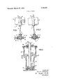
- FIG. 1 is a diagrammatic view of the device of this invention for unwinding yarn spools
- FIG. 2 is a view corresponding to FIG. 1 and showing the displacement of the axis of rotation of the spindle and spool when the unwinding device is in operation;
- FIG. 3 is an enlarged view in partial section showing a first embodiment of an elastic mounting for the spindle
- FIG. 4 is an enlarged partial view in section showing a second embodiment of the elastic mounting for the spindle; v
- FIG. 5 is a partial view in section showing a third embodiment of the elastic mounting for the spindle.
- FIG. 6 shows the unwinding spindle arrangement of this invention in use with a rewinding device of the transverse winding frame type.
- Unwinding device 1 includes an elongated spindle assembly including a shaft 2 which is mounted for rotation in spaced apart bearings 3 and 4 mounted within a hollow cylindrical sleeve 5.
- Sleeve 5 has spaced apart exterior flanges 6 and 7 which are disposed respectively on opposite sides of a support plate 8.
- Interposed between flange 6 and support plate 8 is an elastic element in the form of a rubber ring 9.
- Interposed between the upper surface of flange 7 and the lower surface of support plate 8 is a second elastic element in the form of a rubber ring 10.
- a yarn spool 11, full of thread, is mounted on a spindle or mandrel 13 which is secured to the upper end of shaft 2 for rotation with the shaft.
- Shaft 2 and spindle 13 have an axis of rotation 12 which is along the center of gravity of these elements.
- the center of gravity 12a of the spool is usually not along the axis of the spool 11, but is, for example, offset to one side of the axis.
- the common center of gravity S of the spool 11 and spindle 13 is offset from the axis 12 of the spindle by a distance c.
- the weight of the spindle assembly is relatively great in relation to the weight of the mounted spool.
- such weight is provided by using a spindle 13 of substantial mass such as a solid bar of heavy material like steel, copper or even lead.
- the spindle I3 and shaft 2 are each carefully balanced so their centers of gravity lie along the axis 12.
- the weight of the spindle 13 is at least several times that of the filled spool 11.
- spindle 13 is mounted on the upper end of shaft 2 and the lower end of shaft 2 is supported in the bearings 3 and 4 so the spindle assembly can swing around the center of tilt 13b which is substantially co-planar with plate 8.
- the spool 11 is a substantial distance from the tilt point 13b of the spindle assembly. It has been found that a distance between the center of gravity of the spool and the center of tilt 13b which is at least equal to 1 8: times the height of the spool works satisfactorily whereas in some instances this distance can be substantially greater for example, more than twice the height of the spool, as shown at FIGS. 1 and 2.
- the spindle 13 is seen to be of solid metal construction and'is mounted on the upper end of shaft 2 for rotation with the shaft by a keyed or splined connection 14.
- a supporting sleeve 15a for the lower end of shaft 2 is hollow and elongated and includes an integral outwardly projecting flange 16 which is vertically above the mid-point of the sleeve.
- the lower portion of sleeve 15a is provided with external threads 18 to receive a nut 17 which, when it is tightened, axially clamps against the resilient element 15.
- annular portion 16a and 16b which project between the upper surface of plate 8 and the lower surface of flange 16 and the lower surface of plate 8 and the lower surface of flange 16 and the lower surface of plate 8 and the upper surface of washer 17a, respectively.
- the annular portions are joined by a tubular body 17b.
- the respective ends of the sleeve 15a are recessed. to receive the bearings 3 and 4 and suitable dust covers or end caps 3a and 4a are mounted on the ends of the sleeve to minimize the entry of foreign matter into the bearings.
- the lower end 18a of shaft 2 is turned to a reduced diameter so shoulder 18b of the shaft seats on the top surface of bearing 4.
- Shaft 2 and bearing 4 are held in position against axial movementrelative toth'e sleeve by a retaining clip 18b, which engages suitable grooves in the inside of the sleeve and the outside of the lower end 18a of the shaft.
- FIG. 4 shows a second embodiment of the mounting arrangement for the spindle assembly.
- the bearings 3 and 4 and the configuration of the lower end of the shaft are the same as in the embodiment of FIG. 3.
- the sleeve 15b only has one radially extending circular flange 19 which is integral with the sleeve.
- Sleeve 15a is resiliently connected to support plate 20a by resilient assemblies including a resilient cylindrical element 20 bonded at its opposite ends to the securing elements 21a and 21b.
- the elements 21a and 21b each have a threaded stud 21 secured to same -and projecting therefrom. Suitable nuts 23 are threaded on the several stud portions 21 to mount support sleeve 15b on support plate 20d.
- the bearings 3 and 4 are each resiliently mounted for radial movement.
- shaft 2 extends through bearing 3 and has its lower end seated in bearing 4 in the manner explained for the embodiment of FIG. 3.
- bearing 4 extends into a suitable recess in the lower end of a flanged collar 24a.
- Collar 24a is resiliently mounted in a hollow cylindrical resilient element 24 which surrounds the body 24!) of the 'collar and on which the lower surface of flange 24c of the collar seats.
- the resilient element 24 is so dimensioned that collar 24a is free floating and is spaced from the bottom 25a of a cylindrical sleeve 25 which is secured to the plate 8.
- the bearing assembly including the bearing 4 and collar 24a are resiliently mounted for movement in a radial direction.
- Bearing 3 is positioned in a collar 27 and is retained against axial displacement by an inwardly projecting flange 27a of the collar and a snap ring 275.
- diaphragm 26 is formed from soft rubber and is connected to collar 27 and the upper end of cup 28 by vulcanization or by a suitable adhesive.
- the hollow resilient element 24, while elastic, is more rigid than the diaphragm 26 so shaft 2 can tilt at a location offset toward the lower end of the shaft.
- collars 27 and 240 have a mass which is substantially less than the mass or weight of the sleeves and flanges of the embodiments of FIG. 1-4.
- the cup shaped element 28 which forms a support for upper bearing 3 is secured to support plate 8a and has an opening 28a through which the shaft 2 extends. Both the opening 28a in the cup and the opening through plate 8a are sufflciently large that shaft 2 can tilt or oscillate without engaging the sides of these openings during-an unspooling operation.
- FIG. 6 shows the unwinding device mounted on a transverse winding frame 29, which represents one form of rewinder with which the unwinding device of this invention can be used.
- the transverse winding frame 29 includes a thread guide 30 in the form of an eye through which thread 36 from spool 11 extends.
- there are a plurality of spaced-apart pins which form a thread braking and tensioning device 31 through which thread 36 travels prior to being rewound on the spool 33 which rotates about a horizontal axis.
- the braking and tensioning device 31 are mounted on a suitable arm 35 secured to the base 34 of the transverse winding frame.
- the arrangement includes a guide 32 for insuring that thread is wound on spool 33 in the desired predetermined pattern.
- the shaft 2 and spindle 13 are arranged to rotate about a vertical axis and thread 36 is drawn tangentially from spool 11.
- the transverse winding frame 29 is only exemplary of a rewinding apparatus with which the unwinding device 1 of this invention can be used.
- the respective resilient elements 15, 20, 24 and 26 are formed from elastic or resilient material such as rubber or a resilient plastic material.
- these elements can be formed from a foam or cellular rubber, or a soft foam cellular material such as a polyurethane.
- the spindle 13 is so dimensioned that the spool 11 is merely thrust onto the spindle and is frictionally held thereon for rotation with the spindle during the thread unwinding operation.
- Apparatus for rapidly unwinding yarn from a spool comprising, in combination,
- a spindle having an axis and including means to mount a spool of yarn thereon for rotation with the spindle, and
- mounting means mounting said spindle for rotation, said mounting means comprising bearing means and means mounting said bearing means for movement in a direction transversely of the axis of the spindle to allow said spindle and spool to rotate about an axis passing through the common center of gravity of the spindle and spool.
- said bearing means includes a first bearing, and a second bearing spaced from said first bearing and in a direction along the axis of the spindle;
- said means mounting said bearing means for transverse movement includes resilient means.
- said resilient means comprises first resilient means mounting said first bearing for transverse movement, and second resilient means mounting said second hearing for transverse movement.
- one of said resilient means is a resilient diaphragm secured between a bearing and a fixed support.
- said resilient means mounts said sleeve for limited transverse movement.
- said resilient means comprises an annular resilient element surrounding said sleeve and mounting the sleeve on a rigid support.
- said resilient means comprises a plurality of elongated resilientelements in circumferentially spaced relation around the sleeve and connected between the sleeve and a rigid support.
- a fixed support plate has an opening therethrough
- said sleeve extends through said opening
- said resilient means has a portion thereof engaging one face of said plate and another portion engaging the other face of said plate;
- clamp means on said sleeve in spaced relation to said flange and clamping said first resilient portion between said flange and plate and said second resilient portion between said clamp means and said plate.
- Apparatus for rapidly unwinding yarn from a spool comprising, in combination a. a shaft,
- a spindle connected to said shaft for rotation with the shaft and including means to mount a spool of yarn thereon for rotation with the spindle, and
- Apparatus for rapidly unwinding yarn from a spool comprising, in combination a. a spindle having an axis and including means to mount a spool of yarn thereon for rotation with the spindle, said spindle including a weight having its center of gravity along the axis of the spindle, said weight having a mass several times the mass of the spool and thread on said spindle,and b. mounting means mounting said spindle for rotation, said mounting means includingmeans for al-' lowing said spindle and spool to rotate about an axis passing through the common center of gravity of the spindle and spool.
- Apparatus for rapidly unwinding yarn from a spool comprising, in combination a. a spindle having a longitudinal axis,
Landscapes
- Storage Of Web-Like Or Filamentary Materials (AREA)
- Winding Filamentary Materials (AREA)
- Unwinding Of Filamentary Materials (AREA)
- Tension Adjustment In Filamentary Materials (AREA)
Applications Claiming Priority (1)
| Application Number | Priority Date | Filing Date | Title |
|---|---|---|---|
| DE2102696A DE2102696C3 (de) | 1971-01-21 | 1971-01-21 | Vorrichtung zum Abziehen eines Fadens von einer Spule |
Publications (1)
| Publication Number | Publication Date |
|---|---|
| US3722826A true US3722826A (en) | 1973-03-27 |
Family
ID=5796487
Family Applications (1)
| Application Number | Title | Priority Date | Filing Date |
|---|---|---|---|
| US00132766A Expired - Lifetime US3722826A (en) | 1971-01-21 | 1971-04-09 | Unwinding device for yarn spools |
Country Status (6)
| Country | Link |
|---|---|
| US (1) | US3722826A (2) |
| JP (1) | JPS5522389B1 (2) |
| CH (1) | CH528434A (2) |
| DE (1) | DE2102696C3 (2) |
| ES (1) | ES399041A1 (2) |
| FR (1) | FR2122980A5 (2) |
Cited By (1)
| Publication number | Priority date | Publication date | Assignee | Title |
|---|---|---|---|---|
| US3865330A (en) * | 1972-07-10 | 1975-02-11 | Uster Spindel Motoren Maschf | Bobbin spindle |
-
1971
- 1971-01-21 DE DE2102696A patent/DE2102696C3/de not_active Expired
- 1971-04-09 US US00132766A patent/US3722826A/en not_active Expired - Lifetime
-
1972
- 1972-01-14 CH CH50472A patent/CH528434A/de not_active IP Right Cessation
- 1972-01-20 FR FR7201850A patent/FR2122980A5/fr not_active Expired
- 1972-01-20 ES ES399041A patent/ES399041A1/es not_active Expired
- 1972-01-21 JP JP820972A patent/JPS5522389B1/ja active Pending
Cited By (1)
| Publication number | Priority date | Publication date | Assignee | Title |
|---|---|---|---|---|
| US3865330A (en) * | 1972-07-10 | 1975-02-11 | Uster Spindel Motoren Maschf | Bobbin spindle |
Also Published As
| Publication number | Publication date |
|---|---|
| CH528434A (de) | 1972-09-30 |
| DE2102696A1 (de) | 1972-08-03 |
| DE2102696C3 (de) | 1979-03-22 |
| DE2102696B2 (de) | 1978-07-20 |
| ES399041A1 (es) | 1974-10-16 |
| FR2122980A5 (2) | 1972-09-01 |
| JPS5522389B1 (2) | 1980-06-17 |
Similar Documents
| Publication | Publication Date | Title |
|---|---|---|
| CN104364550B (zh) | 用于将纱线按压至纱管的装置 | |
| US3917182A (en) | Winding machine | |
| US2576254A (en) | Yarn package support | |
| US3177643A (en) | Double-twist spindle | |
| US3284024A (en) | Means for withdrawing yarn from yarn packages | |
| US4114819A (en) | Apparatus for supporting a bobbin holder shaft in a high speed winder | |
| US4047676A (en) | Winder vibration dampener | |
| US3923261A (en) | Spindle for a winding machine | |
| US3596845A (en) | Textile machine | |
| US3722826A (en) | Unwinding device for yarn spools | |
| US1233064A (en) | Bobbin-holder. | |
| US3703263A (en) | Cord tensioning device | |
| US2170764A (en) | Yarn swift | |
| US4280668A (en) | Thread-storage and delivery device for textile machines | |
| US3831869A (en) | Holding means for yarn winding carrier which is to rotate at high speeds | |
| US2610806A (en) | Constant tension winding | |
| US2173762A (en) | Apparatus for twisting filaments, threads, bands, and the like | |
| US2755027A (en) | Textile bobbin drive | |
| US2865577A (en) | Spool holding arrangement | |
| US4013238A (en) | Device for controlling the balloon and tension in the thread from a thread storing and distributing apparatus to an operating machine | |
| US1917914A (en) | Machine for spinning, doubling, twisting, and the like, yarns, fibers, and the like | |
| US3861606A (en) | Yoke apparatus for yarn carriers | |
| US2546301A (en) | Cone holder for creels | |
| US3276718A (en) | Non-rotating windup chuck | |
| US5004170A (en) | Apparatus for compensating sag of the mandrel of a winding machine |