US3768101A - Trimming apparatus - Google Patents
Trimming apparatus Download PDFInfo
- Publication number
- US3768101A US3768101A US00227348A US3768101DA US3768101A US 3768101 A US3768101 A US 3768101A US 00227348 A US00227348 A US 00227348A US 3768101D A US3768101D A US 3768101DA US 3768101 A US3768101 A US 3768101A
- Authority
- US
- United States
- Prior art keywords
- guide
- panels
- center line
- guide means
- longitudinal center
- Prior art date
- Legal status (The legal status is an assumption and is not a legal conclusion. Google has not performed a legal analysis and makes no representation as to the accuracy of the status listed.)
- Expired - Lifetime
Links
- 238000009966 trimming Methods 0.000 title claims abstract description 56
- 239000000463 material Substances 0.000 claims abstract description 12
- 241000283690 Bos taurus Species 0.000 claims description 10
- 239000013536 elastomeric material Substances 0.000 claims description 7
- 230000003111 delayed effect Effects 0.000 claims description 3
- 230000004048 modification Effects 0.000 description 2
- 238000012986 modification Methods 0.000 description 2
- 241000153282 Theope Species 0.000 description 1
- 230000001143 conditioned effect Effects 0.000 description 1
- 238000004519 manufacturing process Methods 0.000 description 1
- 238000005096 rolling process Methods 0.000 description 1
- 239000004576 sand Substances 0.000 description 1
Images


Classifications
-
- B—PERFORMING OPERATIONS; TRANSPORTING
- B26—HAND CUTTING TOOLS; CUTTING; SEVERING
- B26D—CUTTING; DETAILS COMMON TO MACHINES FOR PERFORATING, PUNCHING, CUTTING-OUT, STAMPING-OUT OR SEVERING
- B26D3/00—Cutting work characterised by the nature of the cut made; Apparatus therefor
- B26D3/006—Cutting work characterised by the nature of the cut made; Apparatus therefor specially adapted for cutting blocs of plastic material
-
- Y—GENERAL TAGGING OF NEW TECHNOLOGICAL DEVELOPMENTS; GENERAL TAGGING OF CROSS-SECTIONAL TECHNOLOGIES SPANNING OVER SEVERAL SECTIONS OF THE IPC; TECHNICAL SUBJECTS COVERED BY FORMER USPC CROSS-REFERENCE ART COLLECTIONS [XRACs] AND DIGESTS
- Y10—TECHNICAL SUBJECTS COVERED BY FORMER USPC
- Y10T—TECHNICAL SUBJECTS COVERED BY FORMER US CLASSIFICATION
- Y10T83/00—Cutting
- Y10T83/647—With means to convey work relative to tool station
- Y10T83/6476—Including means to move work from one tool station to another
- Y10T83/6489—Slitter station
- Y10T83/6491—And transverse cutter station
-
- Y—GENERAL TAGGING OF NEW TECHNOLOGICAL DEVELOPMENTS; GENERAL TAGGING OF CROSS-SECTIONAL TECHNOLOGIES SPANNING OVER SEVERAL SECTIONS OF THE IPC; TECHNICAL SUBJECTS COVERED BY FORMER USPC CROSS-REFERENCE ART COLLECTIONS [XRACs] AND DIGESTS
- Y10—TECHNICAL SUBJECTS COVERED BY FORMER USPC
- Y10T—TECHNICAL SUBJECTS COVERED BY FORMER US CLASSIFICATION
- Y10T83/00—Cutting
- Y10T83/647—With means to convey work relative to tool station
- Y10T83/6572—With additional mans to engage work and orient it relative to tool station
- Y10T83/6576—By opposed lateral guide means
-
- Y—GENERAL TAGGING OF NEW TECHNOLOGICAL DEVELOPMENTS; GENERAL TAGGING OF CROSS-SECTIONAL TECHNOLOGIES SPANNING OVER SEVERAL SECTIONS OF THE IPC; TECHNICAL SUBJECTS COVERED BY FORMER USPC CROSS-REFERENCE ART COLLECTIONS [XRACs] AND DIGESTS
- Y10—TECHNICAL SUBJECTS COVERED BY FORMER USPC
- Y10T—TECHNICAL SUBJECTS COVERED BY FORMER US CLASSIFICATION
- Y10T83/00—Cutting
- Y10T83/647—With means to convey work relative to tool station
- Y10T83/6579—With means to press work to work-carrier
-
- Y—GENERAL TAGGING OF NEW TECHNOLOGICAL DEVELOPMENTS; GENERAL TAGGING OF CROSS-SECTIONAL TECHNOLOGIES SPANNING OVER SEVERAL SECTIONS OF THE IPC; TECHNICAL SUBJECTS COVERED BY FORMER USPC CROSS-REFERENCE ART COLLECTIONS [XRACs] AND DIGESTS
- Y10—TECHNICAL SUBJECTS COVERED BY FORMER USPC
- Y10T—TECHNICAL SUBJECTS COVERED BY FORMER US CLASSIFICATION
- Y10T83/00—Cutting
- Y10T83/647—With means to convey work relative to tool station
- Y10T83/6584—Cut made parallel to direction of and during work movement
- Y10T83/6603—Tool shiftable relative to work-conveying means
-
- Y—GENERAL TAGGING OF NEW TECHNOLOGICAL DEVELOPMENTS; GENERAL TAGGING OF CROSS-SECTIONAL TECHNOLOGIES SPANNING OVER SEVERAL SECTIONS OF THE IPC; TECHNICAL SUBJECTS COVERED BY FORMER USPC CROSS-REFERENCE ART COLLECTIONS [XRACs] AND DIGESTS
- Y10—TECHNICAL SUBJECTS COVERED BY FORMER USPC
- Y10T—TECHNICAL SUBJECTS COVERED BY FORMER US CLASSIFICATION
- Y10T83/00—Cutting
- Y10T83/727—With means to guide moving work
- Y10T83/734—With attachment or operative connection to tool carrier
-
- Y—GENERAL TAGGING OF NEW TECHNOLOGICAL DEVELOPMENTS; GENERAL TAGGING OF CROSS-SECTIONAL TECHNOLOGIES SPANNING OVER SEVERAL SECTIONS OF THE IPC; TECHNICAL SUBJECTS COVERED BY FORMER USPC CROSS-REFERENCE ART COLLECTIONS [XRACs] AND DIGESTS
- Y10—TECHNICAL SUBJECTS COVERED BY FORMER USPC
- Y10T—TECHNICAL SUBJECTS COVERED BY FORMER US CLASSIFICATION
- Y10T83/00—Cutting
- Y10T83/727—With means to guide moving work
- Y10T83/741—With movable or yieldable guide element
- Y10T83/743—Opposed to work-supporting surface
-
- Y—GENERAL TAGGING OF NEW TECHNOLOGICAL DEVELOPMENTS; GENERAL TAGGING OF CROSS-SECTIONAL TECHNOLOGIES SPANNING OVER SEVERAL SECTIONS OF THE IPC; TECHNICAL SUBJECTS COVERED BY FORMER USPC CROSS-REFERENCE ART COLLECTIONS [XRACs] AND DIGESTS
- Y10—TECHNICAL SUBJECTS COVERED BY FORMER USPC
- Y10T—TECHNICAL SUBJECTS COVERED BY FORMER US CLASSIFICATION
- Y10T83/00—Cutting
- Y10T83/727—With means to guide moving work
- Y10T83/744—Plural guide elements
- Y10T83/745—Opposed
Definitions
- ABSTRACT [52] US. Cl 83/408, 83/420, 83/422,
- the apparatus includes a Pair [58] Field of Search 83/372 408 367 0f trim Swim interconnected by a transfer 83,441 446 447 449 450 4 wherein the respective trimming machines trim at 1 Q least a pair of sides.
- Each of the trimming machines are adjustable automatically to compensate for varia- [56] References Cited tions in width as well as height of the panels of mate- UNITED STATES PATENTS "1 1,235,006 7/1917 Butler et a1.
- This invention relates generally to an apparatus for trimming panels of elastomeric material on its four sides which handles panels of elastomeric material of variant sizes with rind or flashing on the respective sides and trims the rind therefrom automatically.
- FIG. 1 is a side elevational'view of the first trimming machine of the present invention
- FIG. 2 is a plan view of the first trimming machine shown in FIG. 1;
- FIG. 3 is a cross-sectional view of the first trimming machine directed towards the trimming knives with the guide means inoperative position; i I
- FIG. 4 is a cross-sectional view of the forward portion of the first trimming machine similar to FIG. 3 except showing the guide means in nonoperative position;
- FIG. 5 is a fragmentary cross-sectional view of a modified form of the apparatus shown in FIG. 4;
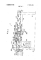
- FIG. 6 is a plan view of the entiretrimming apparatus
- FIG. 7 is a plan view of the transfer means between the first and second trimming machines of the trimming apparatus.
- FIG. 8 is an end elevational view of the transfer-apparatus
- FIG. 9- is a side elevational view of the transfer apparatus in the receiving position
- FIG. 10 is a side elevational view of the transfer apparatus showing one set of rollers in the conveying posi- DETAILED DESCRIPTION
- the first trimming machine 1 has suitable framework for supporting vertically extending pairs of support legs 4 and Sand longitudinally extending side brackets 6 and 7 (FIGS. 3 and 4). Such framework supports at the respective end portions thereof, a pair of spaced shafts 8 and 9 with rollers 11 and 12 respectively.
- An endless conveyor belt having a conveying run 10 and a return run 14 is trained about the respective rollers 11 and 12.
- a motor 15 is suitably mounted between a pair of support legs 55 having its output shaft connected by a pulley belt 16 to a drive shaft 9 and roller 12 which, in turn, moves the endless conveyor belt in its orbital movement about rollers 11 and 12.
- a cross brace 20 (FIG. 1) mounted on the one end portion of the framework pivotally supports two pairs of lever arms 21 which have their outboard ends journaling for rotation rollers 22, which rollers 22 are adapted to rollingly engage the panels of elastomeric material to be described.
- Mounted on the respective brackets 23 are guide blocks 30. Each guide block is similarly constructed and only one will be described. 4
- Guide block 30 has a pair of vertically and horizontally disposed recesses which rotatably receive rollers 31.
- each guide block 30 has a longitudinally extended recess which is in alignment with one rolling surface of each roller 31 such that a guide bar 32 received by a pair of transversely aligned guide blocks 30 rollingly engages the respective rollers 31 of both guide blocks,thereby accurately guiding the reciprocal movement of the guide bars 32
- a .pair of brackets (FIG. 1) 33 are mounted on side bracket 6 to rotatably secure a pulley 34.
- a laterally extendingbar 35- is secured to' the respective one end portions of guide bars 32 with the intermediate portion of bar 35 supporting an eye hook 36.
- a wire 37 trained about pulley 34 has its one end connected to a weight 38 and its other end secured to eye hook 36 thereby biasing the respective guide bars 32 in a leftward direction as viewed in FIG. 4.
- Guide plate member 40 Pivotally secured to the one end of table 27 is a guide plate member 40.
- Guide plate member 40 has a plurality of recesses which receive rollers 41 journaled therein which, as shown in FIG. 1, has vertically disposing axes.
- a pair of spaced brackets 43' and 44 (FIG. 1)
- each rod 45 are secured close to the respective end portions of guide plate member 40 and each guide plate member 40 supports for movement thereon arod 45.
- the respective lower ends of each rod 45 are suitably connected to a longitudinally extended pressure plate member 46 which, as shown in FIG. 1, has an inclined portion at the forwardly most portion to facilitate the movement of the panels of elastomeric stock thereunder.
- the other end portion of each rod 45 has a nut 48 suitably threaded thereon.
- a spring 49 Encompassing each rod 45 between pressure plate member 46 and brackets 43 and 44 is a spring 49 which biases pressure plate member 46 downwardly for engagement with a panel memher in a manner to be described.
- a panel member 50 as shown in FIG. 6 is substantially square in plan view having rind or flashing 51, 52, on the respective side portions and rind or flashing 53,54 on the respective end portions. As seen in FIG. 3, the panel 50 is held in position by the pressure plate members 46 whereas in FIG. '44 such panel 50 is in a position to be engaged by the pressure plate members and centered thereby in a manner to be described.
- the guide plate member 40 has its intermediate portion suitably connected to a pair of lever members (FIGS. 3 and 1) which, in turn, are pivotally connected to the piston rod 56 of a pneumatic cylinder 57.
- Pneumatic cylinder 57 is journaled for pivotal movement on the framework by a pair of brackets which, as shown in plan view in FIG. 2, facilitate the pivotal movement of the guide plate 40 along with the pressure plate member 46.
- guide plate member 60 (FIGS. 3 and 4) which pivotally supports guide plate member 61 similar in all respects to the previously described guide plate member 40.
- Guide plate member 61 has a plurality of recesses which journal for rotation rollers 63 whose forwardly most disposed portion is tangent to each other to facilitate the movement of a panel of elastomeric material therethrough.
- Guide plate member 61 has secured to the upper most end portion a pair of space end brackets 65,66 (FIG. 2) which journal for vertical movement a pair of guide rods 67 whose respective end portions are secured to a guide plate 68 and whose upper end receives a threaded nut 69.
- springs 70 having one end portion in abutting engagement with the pressure plate 68 and whose upper end is in abutting contact with the brackets 65 and 66, respectively.
- a longitudinally extending plate member 72 Mounted closely adjacent to longitudinally extending bracket member 60, on the underside of bars 32, is a longitudinally extending plate member 72 to which is secureda pair of brackets 73 (FIG. 2) which pivotally support cylinder 75.
- Cylinder-.75 has its piston rod suitably connected toa pair of lever members 76 which, in turn, are secured to guide plate member 61 to facilitate the pivotal movement of the guide plate member 61 along with the pressure plate 68.
- motors 80 and 81 (FIG. 2) having their output end suitably connected to rotary cutters 82 and 83 which are adapted to trim the rind from the respective side portions of the panels 50.
- Motor 81 and cutter 83 are mounted on plate member 72 for movement laterally with the guide bars 32 in response to the biasing action of weight 38.
- projections 85 on the guide bars 32 are operative to engage adjustable stops 86 in support legs 5.
- the guide plate members 40, 61 and pressure plate members 46 and 68 cooperate to act as guide means for the positioning of a panel as it moves past the cutters 82 and 83.
- Transfer apparatus 2 has suitable framework including upwardly extending legs 90 and a horizontally extending table 91.
- the respective legs 90 are interconnected by braces and supports 92-92, which supports 92-92 have a plurality of bushings 93 which guide rods 94 in their reciprocal movement therethrough.
- the one end of the respective rods 94 are connected to a plate member 95 which supports a motor 96.
- the other end portions of rods 94 are connected to horizontally disposed plate members 97.
- Another plate member 38 extendsin the same direction as plate members 97 having secured to it the piston rod of a pneumatic cylinder 100. The energization of the head end of cylinder moves plate member 98 upwardly whereas pressurization of the rod and of cylinder 100 moves the plate member 98 downwardly along with supporting rollers ina manner to be described. 5
- brackets 102 and 103 Extending laterally between brackets 102 and 103 are plurality of shafts 105 which have journaled for rotation thereon a plurality of rollers 106.
- the respective end portions of brackets 102 and 103 support shafts 108 and 109, respectively, which shafts, in turn, have keyed thereto pairs of sprockets 110 and 111, respectively.
- Shaft 109 is driven by a chain 112 connected to the output end of motor 96.
- Chains 115 and 116 are'trained about sprockets 110 and 111, respectively, such that upon energization of motor 96, chains 115 and 116 will orbit as sprockets 110 and 11.1 rotate.
- chains 115 and 1 16 Suitably connected to chains 115 and 1 16 are a pair of cleats l 17 and 1 18 to facilitate the movement of panels 50 in a manner to be described.
- Table 91 supports a plurality of vertically extending pairs of brackets 120.
- Each pair of brackets 120 supports rollers 121 (FIG. 10).
- the respective pairs of brackets 120 are shorter as one moves further away from trimming machine No. 1. This action facilitates the removal of a panel of elastomeric material away from trimming machine 1.
- the axes ofrollers 121 are at right angle to .rollers 106. e
- FIG. 9 discloses. a panel 50 entering the transfer apparatus while FIG. 10 discloses such panelin a raised position wherein the panel is out of contact with the respective rollers 121.
- a pair of stops'122 are located at one end of the transfer means 2 as disclosed in plan view of FIG. 6 with an electric eye 123 located adjacent thereto, which electric eye operates the energization of the valve that controls the energization of pneumatic cylinder 100 as well as a time delayed switch which energizes motor 96. .
- Trimming machine 3 (FIG. 6) is similar to trimming machine 1 having an endless conveyor belt with spaced guide plate members 131 and 132 supporting rollers 133 similar to the guide plate members 40 and 61 in trimming machine 1.
- Guide plate members 131 and 132 support pressure plate members 134 and 135.
- Guide plate member 131 along with pressure plate member 134 is stationary as in the first embodiment while guide plate member 132 along with pressure plate member 135 is movable by cylinder means similar to cylinder 75 of trimming machine 1 shown in FIG. 4.
- Trimming machine 3 has a pair of laterally spaced motors 138 and 139 supporting rotary knives that remove the rind or flashing 53 and 54 from the respective ends of panel 50.
- Motor 139 along with pressure'plate 135, is movable laterally in the same manner as motor 81 and pressure plate '68.
- the only difference between trimming machine 3 with that of trimming machine 1 is that trimming machine 3 has a different type of conveying means for moving the panels of elastomeric materials therethrough.
- Such conveying means for 'trimming machine 3 includes laterally extending brackets 140 (FIGS. 6, 11, and 12) at one end of the machine which supports a motor 142.
- Brackets 140 support a pair of outwardly extending brackets 143 which journal for rotation a shaft 144.
- a sprocket 145 is keyed to shaft 144, which sprocket 145 is connected to the output shaft of motor 142 by a chain 146.
- a laterally extending bracket 150 which supports a pair of brackets 151 which journals for rotation a shaft 152.
- Shaft 152 has a pair of sprockets 153 and 154 suitably keyed thereto.
- a chain 160 is trained about sprocket 153 and a sprocket 162 keyed to shaft 144 while a chain 161 is trained about sprocket 154 and a sprocket 163 which keyed to shaft 144'such that energization of motor 142 will orbit the chains 160 and 161.
- Chains 160 and 161 are interconnected by laterally extending brackets 164 and 165.
- brackets 164' and 165 FIG.
- Cylinder 57 is actuated prior to that of cylinder 75 such that guide plate member 40 is pivoted into a vertical position which tends to push the panel 50 in anupward direction as viewed in FIG. 6 (plan view) which is toward the top of the page.
- guide plate member 61 is pivoted into a vertical position along with a biasing action of weight 38 acting through rod members 32 to center the panel member'in a longitudinally extending direction along the path of movement of panel while being conveyed by the conveying run 10.
- Such action moves the pressure plate members 46 52 and 51 from the panel 50 as such panel is conveyed past the cutters by the movement of the conveying run 10 of the endless conveyor.
- the panel 50 on conveyor 130 is positioned in the same manner as on conveying run 10 of trimming machine '1 wherein the respective pressure plates 134, 135, along with guide plate members 131'and 132, position the panel with guide plate members 131 being stationary and guide plate member 132 moving laterally to adjust for the width of thepanel.
- motor 139 adjusts along with the plate member 132 as motor 81 and cutter 83 in trimming machine 1. The panel is trimmed by cutter 83 as it is discharged by trimming machine 3.
- FIG. 5 A modification of the described apparatus is shown in FIG. 5 wherein the weight 38 is replaced by a spring biased pneumatic cylinder 165 which is secured by bracket 166 to the supporting structure of the apparatus.
- the piston rod of cylinder 165 is secured to the plate member 72 which in turn is secured to the guide bars 32.
- a spring 167 is mounted in the head end of cylinder 165 such that it biases the guide bar 32 leftwardly as shown in FIG. 5. Pressurization of the rod end of cylinder 165 moves the bars 32 along with the guide plate member 61 and the pressure plate 68 rightwardly as viewed in FIGS to assure greaterflexibility in handling different widthsof stock.
- the overall operation is the' vention is not limited thereto since variations and modifications thereof can be made without departing from the principles of the invention.
- An apparatus for processing panels of elastomeric I material comprising support means, conveyor means with a longitudinal center line mounted on said support means for conveying said panels, afirst guide means pivotally mounted on one side of said support means, a support member slidably mounted on the other side of said support means for movement toward and away from said longitudinal center line, biasingmeans operatively connected to said support member for biasing said support member toward said longitudinal center line a pair of cutters at one end of said conveyor means for trimming the respective side edges of a panel passing thereby, one of said cutters mounted on said support member for movement therewith, the other of said cutters mounted on said support means in alignment with said first guide member, a second guide means pivotally mounted on said support member and for movement therewith, and power operated means connected to said guide means respectively for pivoting said guide means between an inoperative position and an operative position forguiding contact with a panel being conveyed by said conveyor means.
- each of said guide means includes a longitudinally extending guide plate member with recesses therein, each of said recesses having a roller therein, the axes of said rollers being vertical in the operative position of said guide members, a plane tangent to the respective rollers being respectively in alignment with said cutters, and each of said guide members having a resiliently mounted pressure plate biased downward toward said conveyor means and being normal to said supporting longitudinal guide plate member.
- pneumatic cylinder means are connected to said biasing means, said pneumatic cylinder means operative upon energization to act against said biasing means and move said one guide means away from said center line.
- Apparatus for processing panels of sheet material comprising support means, conveyor means for moving panels thereon, said conveyor means having a longitudinal pass line, a pair of laterally spaced cutters at one end of said conveyor means for trimming opposed side edges of a panel passing therebetween, a pair of guide means mounted on said support means on opposite sides of the conveyor means for centering said panel on said conveyor means while passing said cutters, each of said guide means having a resiliently mounted pressure plate movable therewith to adjust for thickness of panels upon movement of said resiliently mounted plates into a horizontally disposed position, one of said guide means movable laterally towards and away from said longitudinal center line, means interconnecting said one guide means and one of said cutters for simultaneous movement, the other said guide means and cutter having a fixed mounting with respect to the longitudinal center line, biasing means connected to said one guide means and said one cutter for biasing said one guide means and said one cutter toward said longitudinal center line to adjust the distance between said cutters in response to the width of a panel received by said conveyor means and said guide means, and power operated means
- each of said guide means has a plurality of rollers having their axes of rotation parallel and in alignment with a plane tangent to their innermost surfaces, and wherein said tangent plane passes through one of said cutters.
- An apparatus for processing panels of elastomeric materials comprising a pair of rindtrimming machines, a transfer means operative to convey panels from one of said machines to the other of said machines, each machine having conveyor means with a longitudinal center line, the extension of said longitudinal center lines intersect and lie at right angles to each other, each of said trimming machines having a pair of spaced cutters mounted on opposite sides of said longitudinal center line for trimming the respective edges of a panel material passing therethrough and which edges of the panels being trimmed of rind are parallel to the longitudinal center line of said conveyor means conveying said panels, each of said trimming machines having a pair of spaced guide means for cooperation with the conveyor means for guiding panels past said cutters, each of said guide means having a guide plate member pivotable about an axis parallel to said longitudinal center line, each of said guide plate members receiving a plurality of rollers, each of said guide plate members having a resiliently held pressure plate for pivotal movement therewith, and each of said pressure plates in the ope ra tive position of said guide means lying in
- said power operated means includes pneumatic cylinder means connected to said guide plate members for pivoting said guide plate members and said pressure plates into and out of operative positions.
Landscapes
- Life Sciences & Earth Sciences (AREA)
- Forests & Forestry (AREA)
- Engineering & Computer Science (AREA)
- Mechanical Engineering (AREA)
- Processing And Handling Of Plastics And Other Materials For Molding In General (AREA)
Abstract
An apparatus for trimming the respective four sides of a flat elastomeric stock. The apparatus includes a pair of trim stations interconnected by a transfer conveyor wherein the respective trimming machines trim at least a pair of sides. Each of the trimming machines are adjustable automatically to compensate for variations in width as well as height of the panels of material.
Description
United States Patent [191 Kuts Oct. 30, 1973 [5 TRIMMING APPARATUS 1,111,170 9/1914 Nall et a1. .1 83/447 X 1,306,642 6 1919 [75] lnventor: Mathew Kuts, Akron, Ohio l985,820 1241934 73 Assigneez v k Corporation, Cincinnati, 3,151,794 10/1964 Brand 83/368 X Ohio Primary ExaminerJ. M Meister [22] Flled' 1972 AttorneyJoseph Januszkiewicz et al. [21] Appl. N0.: 227,348
7 [57] ABSTRACT [52] US. Cl 83/408, 83/420, 83/422,
83/433, 83/44183/447, 83/449 An apparatus for trimming the respective four sides of [51] Int. Cl B23d 19/06 I flat elastomeric Stock The apparatus includes a Pair [58] Field of Search 83/372 408 367 0f trim Swim interconnected by a transfer 83,441 446 447 449 450 4 wherein the respective trimming machines trim at 1 Q least a pair of sides. Each of the trimming machines are adjustable automatically to compensate for varia- [56] References Cited tions in width as well as height of the panels of mate- UNITED STATES PATENTS "1 1,235,006 7/1917 Butler et a1. 83/441 8 Claims, 12 Drawing Figures l TRIMMING APPARATUS BACKGROUND OF THE INVENTION This invention relates generally to an apparatus for trimming panels of elastomeric material on its four sides which handles panels of elastomeric material of variant sizes with rind or flashing on the respective sides and trims the rind therefrom automatically.
In the manufacture of panels of flexible elastomeric stock it is customary to initially trim the rind or flashing.
off the respective sides. Such panels would weigh up to 20 pounds. To trim the flashing, numerous hand manipulations were required because the sheet stock would vary in thickness from one-sixteenth of an inch to onehalf of an inch or more and due to mold shrinkage would vary in width and length. Such hand trimming is time consuming and dangerous: however, such operations were justified in light of the fact that the panels varied in dimensions including thickness, making it im- 4 practical to size and sort the panels into stacks and then provide a machine for a specific size or re-set the ma chine to different sizes; To cut or trim the panels to all one size wasted'unnecessarily valuable material.
SUMMARY-OF THE INVENTION BRIEF DESCRIPTION OF THE DRAWINGS FIG. 1 is a side elevational'view of the first trimming machine of the present invention; I
FIG. 2 is a plan view of the first trimming machine shown in FIG. 1;
FIG. 3 is a cross-sectional view of the first trimming machine directed towards the trimming knives with the guide means inoperative position; i I
FIG. 4 is a cross-sectional view of the forward portion of the first trimming machine similar to FIG. 3 except showing the guide means in nonoperative position;
FIG. 5 is a fragmentary cross-sectional view of a modified form of the apparatus shown in FIG. 4;
' FIG. 6 is a plan view of the entiretrimming apparatus;
FIG. 7 is a plan view of the transfer means between the first and second trimming machines of the trimming apparatus; I
FIG. 8 is an end elevational view of the transfer-apparatus;
FIG. 9-is a side elevational view of the transfer apparatus in the receiving position;
FIG. 10 is a side elevational view of the transfer apparatus showing one set of rollers in the conveying posi- DETAILED DESCRIPTION Referring to the drawings wherein like characters refer to like parts throughout the several views there is shown in FIG. 6 a trimming apparatus having a first trimming machine 1, a transfer means 2, and a second trimmingmachine 3. The first trimming machine 1 has suitable framework for supporting vertically extending pairs of support legs 4 and Sand longitudinally extending side brackets 6 and 7 (FIGS. 3 and 4). Such framework supports at the respective end portions thereof, a pair of spaced shafts 8 and 9 with rollers 11 and 12 respectively. An endless conveyor belt having a conveying run 10 and a return run 14 is trained about the respective rollers 11 and 12. A motor 15 is suitably mounted between a pair of support legs 55 having its output shaft connected by a pulley belt 16 to a drive shaft 9 and roller 12 which, in turn, moves the endless conveyor belt in its orbital movement about rollers 11 and 12. A cross brace 20 (FIG. 1) mounted on the one end portion of the framework pivotally supports two pairs of lever arms 21 which have their outboard ends journaling for rotation rollers 22, which rollers 22 are adapted to rollingly engage the panels of elastomeric material to be described. On the intermediate portion of the framework-are mounted-four vertically extending brackets 23 (FIGS. 1 and 4) which, together with brackets 24, 25, and 26, support a horizontally extending table 27 which, in turn, supports the conveying run 10 of the endless conveyor belt. Mounted on the respective brackets 23 are guide blocks 30. Each guide block is similarly constructed and only one will be described. 4
Guide block 30.has a pair of vertically and horizontally disposed recesses which rotatably receive rollers 31. In addition, each guide block 30 has a longitudinally extended recess which is in alignment with one rolling surface of each roller 31 such that a guide bar 32 received by a pair of transversely aligned guide blocks 30 rollingly engages the respective rollers 31 of both guide blocks,thereby accurately guiding the reciprocal movement of the guide bars 32 A .pair of brackets (FIG. 1) 33 are mounted on side bracket 6 to rotatably secure a pulley 34. A laterally extendingbar 35- is secured to' the respective one end portions of guide bars 32 with the intermediate portion of bar 35 supporting an eye hook 36. A wire 37 trained about pulley 34 has its one end connected to a weight 38 and its other end secured to eye hook 36 thereby biasing the respective guide bars 32 in a leftward direction as viewed in FIG. 4. n
Pivotally secured to the one end of table 27 is a guide plate member 40. Guide plate member 40 has a plurality of recesses which receive rollers 41 journaled therein which, as shown in FIG. 1, has vertically disposing axes. A pair of spaced brackets 43' and 44 (FIG. 1)
are secured close to the respective end portions of guide plate member 40 and each guide plate member 40 supports for movement thereon arod 45. The respective lower ends of each rod 45 are suitably connected to a longitudinally extended pressure plate member 46 which, as shown in FIG. 1, has an inclined portion at the forwardly most portion to facilitate the movement of the panels of elastomeric stock thereunder. The other end portion of each rod 45 has a nut 48 suitably threaded thereon. Encompassing each rod 45 between pressure plate member 46 and brackets 43 and 44 is a spring 49 which biases pressure plate member 46 downwardly for engagement with a panel memher in a manner to be described.
A panel member 50 as shown in FIG. 6 is substantially square in plan view having rind or flashing 51, 52, on the respective side portions and rind or flashing 53,54 on the respective end portions. As seen in FIG. 3, the panel 50 is held in position by the pressure plate members 46 whereas in FIG. '44 such panel 50 is in a position to be engaged by the pressure plate members and centered thereby in a manner to be described. The guide plate member 40 has its intermediate portion suitably connected to a pair of lever members (FIGS. 3 and 1) which, in turn, are pivotally connected to the piston rod 56 of a pneumatic cylinder 57. Pneumatic cylinder 57 is journaled for pivotal movement on the framework by a pair of brackets which, as shown in plan view in FIG. 2, facilitate the pivotal movement of the guide plate 40 along with the pressure plate member 46.
The other end portions of guide bars 32 are secured together by a longitudinally extending bracket member 60 (FIGS. 3 and 4) which pivotally supports guide plate member 61 similar in all respects to the previously described guide plate member 40. Guide plate member 61 has a plurality of recesses which journal for rotation rollers 63 whose forwardly most disposed portion is tangent to each other to facilitate the movement of a panel of elastomeric material therethrough. Guide plate member 61 has secured to the upper most end portion a pair of space end brackets 65,66 (FIG. 2) which journal for vertical movement a pair of guide rods 67 whose respective end portions are secured to a guide plate 68 and whose upper end receives a threaded nut 69. Encompassing the respective rods 67 are springs 70 having one end portion in abutting engagement with the pressure plate 68 and whose upper end is in abutting contact with the brackets 65 and 66, respectively. Mounted closely adjacent to longitudinally extending bracket member 60, on the underside of bars 32, is a longitudinally extending plate member 72 to which is secureda pair of brackets 73 (FIG. 2) which pivotally support cylinder 75. Cylinder-.75 has its piston rod suitably connected toa pair of lever members 76 which, in turn, are secured to guide plate member 61 to facilitate the pivotal movement of the guide plate member 61 along with the pressure plate 68.
In the trimming machine 1, there are two guide blocks 30 on the one side and two guide blocks 30 on the other side. Additional blocks 30 for other guide bars 32 may be provided to facilitate the guiding of the guide plate member 61 along with plate member 72.
Mounted on a forwardly disposed portion of the first trimming machine 1 on suitable brackets are motors 80 and 81 (FIG. 2) having their output end suitably connected to rotary cutters 82 and 83 which are adapted to trim the rind from the respective side portions of the panels 50. Motor 81 and cutter 83 are mounted on plate member 72 for movement laterally with the guide bars 32 in response to the biasing action of weight 38. To limit the leftward movement of plate member 72 and the guide bar 32, projections 85 on the guide bars 32 are operative to engage adjustable stops 86 in support legs 5. The guide plate members 40, 61 and pressure plate members 46 and 68 cooperate to act as guide means for the positioning of a panel as it moves past the cutters 82 and 83.
Transfer apparatus 2 has suitable framework including upwardly extending legs 90 and a horizontally extending table 91. The respective legs 90 are interconnected by braces and supports 92-92, which supports 92-92 have a plurality of bushings 93 which guide rods 94 in their reciprocal movement therethrough. The one end of the respective rods 94 are connected to a plate member 95 which supports a motor 96. The other end portions of rods 94 are connected to horizontally disposed plate members 97. Another plate member 38 extendsin the same direction as plate members 97 having secured to it the piston rod of a pneumatic cylinder 100. The energization of the head end of cylinder moves plate member 98 upwardly whereas pressurization of the rod and of cylinder 100 moves the plate member 98 downwardly along with supporting rollers ina manner to be described. 5
The respective end portions of plate members 9797 and plate member 98 are connected to spaced brackets 102 and 103 (FIG. 7) to facilitate their simultaneous reciprocation in accordance with the energization of cylinder 100. Extending laterally between brackets 102 and 103 are plurality of shafts 105 which have journaled for rotation thereon a plurality of rollers 106. The respective end portions of brackets 102 and 103 support shafts 108 and 109, respectively, which shafts, in turn, have keyed thereto pairs of sprockets 110 and 111, respectively. Shaft 109 is driven by a chain 112 connected to the output end of motor 96. Chains 115 and 116 are'trained about sprockets 110 and 111, respectively, such that upon energization of motor 96, chains 115 and 116 will orbit as sprockets 110 and 11.1 rotate. Suitably connected to chains 115 and 1 16 are a pair of cleats l 17 and 1 18 to facilitate the movement of panels 50 in a manner to be described.
Table 91 supports a plurality of vertically extending pairs of brackets 120. Each pair of brackets 120 supports rollers 121 (FIG. 10). The respective pairs of brackets 120 are shorter as one moves further away from trimming machine No. 1. This action facilitates the removal of a panel of elastomeric material away from trimming machine 1. The axes ofrollers 121 are at right angle to .rollers 106. e
' FIG. 9 discloses. a panel 50 entering the transfer apparatus while FIG. 10 discloses such panelin a raised position wherein the panel is out of contact with the respective rollers 121. A pair of stops'122 are located at one end of the transfer means 2 as disclosed in plan view of FIG. 6 with an electric eye 123 located adjacent thereto, which electric eye operates the energization of the valve that controls the energization of pneumatic cylinder 100 as well as a time delayed switch which energizes motor 96. .These items are conventionalin the art and, accordingly, will not be described.
Trimming machine 3 (FIG. 6) is similar to trimming machine 1 having an endless conveyor belt with spaced guide plate members 131 and 132 supporting rollers 133 similar to the guide plate members 40 and 61 in trimming machine 1. Guide plate members 131 and 132 support pressure plate members 134 and 135. Guide plate member 131 along with pressure plate member 134 is stationary as in the first embodiment while guide plate member 132 along with pressure plate member 135 is movable by cylinder means similar to cylinder 75 of trimming machine 1 shown in FIG. 4. Trimming machine 3 has a pair of laterally spaced motors 138 and 139 supporting rotary knives that remove the rind or flashing 53 and 54 from the respective ends of panel 50. Motor 139, along with pressure'plate 135, is movable laterally in the same manner as motor 81 and pressure plate '68. The only difference between trimming machine 3 with that of trimming machine 1 is that trimming machine 3 has a different type of conveying means for moving the panels of elastomeric materials therethrough. Such conveying means for 'trimming machine 3 includes laterally extending brackets 140 (FIGS. 6, 11, and 12) at one end of the machine which supports a motor 142. Brackets 140 support a pair of outwardly extending brackets 143 which journal for rotation a shaft 144.A sprocket 145 is keyed to shaft 144, which sprocket 145 is connected to the output shaft of motor 142 by a chain 146. At the other end portion of trimming machine 3 adjacent to transfer means 2 is a laterally extending bracket 150 which supports a pair of brackets 151 which journals for rotation a shaft 152. Shaft 152 has a pair of sprockets 153 and 154 suitably keyed thereto. A chain 160 is trained about sprocket 153 and a sprocket 162 keyed to shaft 144 while a chain 161 is trained about sprocket 154 and a sprocket 163 which keyed to shaft 144'such that energization of motor 142 will orbit the chains 160 and 161. Chains 160 and 161 are interconnected by laterally extending brackets 164 and 165. Such brackets 164' and 165 (FIG. 11) are L-shaped in cross section, having one of their leg members tapered to a leading edge to facilitate the pick up of one end of a panel 50 for moving such panel through the trimming machine In the operation of the apparatus described, an operator places a panel of elastomeric material onto the conveying run of trimming machine 1 which conveys the panel of material in a leftward direction as viewed in FIG. 1 until the panel material passes underneath rollers 22 which, in their movement, raises lever arms 21 which actuate a limit switch LS-l as indicated diagrammatically in FIG. 1, which, in turn, actuates cylinders 57 and 75. Cylinder 57 is actuated prior to that of cylinder 75 such that guide plate member 40 is pivoted into a vertical position which tends to push the panel 50 in anupward direction as viewed in FIG. 6 (plan view) which is toward the top of the page. How ever, on 'energization of cylinder 75, guide plate member 61 is pivoted into a vertical position along with a biasing action of weight 38 acting through rod members 32 to center the panel member'in a longitudinally extending direction along the path of movement of panel while being conveyed by the conveying run 10. Such action moves the pressure plate members 46 52 and 51 from the panel 50 as such panel is conveyed past the cutters by the movement of the conveying run 10 of the endless conveyor. K
The movement of the panel to the transfer means 2 is facilitated by the respective rollers 121 descending in height, and as the panel 50 is conveyed onto the transfer means 2, the panel actuates the electric eye 123 which thereby pressurizes the head end of pneumatic cylinder which raises the respective bracket 97 and bracket 98. Stops 122 assure that stopping of the panel in its movement onto the transfer means 2. As the respective rollers 106 move upwardly upon actuation of cylinder 100, the panel 50 is moved upward above the rollers 121 and is conditioned for conveying to the trimming machine 3. After a predetermined time interval after actuation of electric eye 123, motor 96 is energized which begins the orbiting of chains and 116. The pair of cleats 117 and- 118 on chains 116 and 115 engage the end portion of the panel 50 and convey such panel onto the endless conveyor of trimming machine 3. After a predetermined time interval of actuation of motor 96, motor 142 is energized which begins the orbiting of chains and 161 such that the laterally extending brackets 164 or 165 engage the end portion of panel 50 and convey such panel toward the cutters l50' and 151 of motors 138 and 139, respectively, of trimming machine 3. The panel 50 on conveyor 130 is positioned in the same manner as on conveying run 10 of trimming machine '1 wherein the respective pressure plates 134, 135, along with guide plate members 131'and 132, position the panel with guide plate members 131 being stationary and guide plate member 132 moving laterally to adjust for the width of thepanel. In addition, motor 139 adjusts along with the plate member 132 as motor 81 and cutter 83 in trimming machine 1. The panel is trimmed by cutter 83 as it is discharged by trimming machine 3. Y
A modification of the described apparatus is shown in FIG. 5 wherein the weight 38 is replaced by a spring biased pneumatic cylinder 165 which is secured by bracket 166 to the supporting structure of the apparatus. The piston rod of cylinder 165 is secured to the plate member 72 which in turn is secured to the guide bars 32. A spring 167 is mounted in the head end of cylinder 165 such that it biases the guide bar 32 leftwardly as shown in FIG. 5. Pressurization of the rod end of cylinder 165 moves the bars 32 along with the guide plate member 61 and the pressure plate 68 rightwardly as viewed in FIGS to assure greaterflexibility in handling different widthsof stock. The overall operation is the' vention is not limited thereto since variations and modifications thereof can be made without departing from the principles of the invention.
1 claim:
1. An apparatus for processing panels of elastomeric I material comprising support means, conveyor means with a longitudinal center line mounted on said support means for conveying said panels, afirst guide means pivotally mounted on one side of said support means, a support member slidably mounted on the other side of said support means for movement toward and away from said longitudinal center line, biasingmeans operatively connected to said support member for biasing said support member toward said longitudinal center line a pair of cutters at one end of said conveyor means for trimming the respective side edges of a panel passing thereby, one of said cutters mounted on said support member for movement therewith, the other of said cutters mounted on said support means in alignment with said first guide member, a second guide means pivotally mounted on said support member and for movement therewith, and power operated means connected to said guide means respectively for pivoting said guide means between an inoperative position and an operative position forguiding contact with a panel being conveyed by said conveyor means.
2. An apparatus for processing panels as set forth in claim 1 wherein each of said guide means includes a longitudinally extending guide plate member with recesses therein, each of said recesses having a roller therein, the axes of said rollers being vertical in the operative position of said guide members, a plane tangent to the respective rollers being respectively in alignment with said cutters, and each of said guide members having a resiliently mounted pressure plate biased downward toward said conveyor means and being normal to said supporting longitudinal guide plate member.
3. An apparatus for processing panels as set forth in claim 1 wherein pneumatic cylinder means are connected to said biasing means, said pneumatic cylinder means operative upon energization to act against said biasing means and move said one guide means away from said center line.
4. Apparatus for processing panels of sheet material comprising support means, conveyor means for moving panels thereon, said conveyor means having a longitudinal pass line, a pair of laterally spaced cutters at one end of said conveyor means for trimming opposed side edges of a panel passing therebetween, a pair of guide means mounted on said support means on opposite sides of the conveyor means for centering said panel on said conveyor means while passing said cutters, each of said guide means having a resiliently mounted pressure plate movable therewith to adjust for thickness of panels upon movement of said resiliently mounted plates into a horizontally disposed position, one of said guide means movable laterally towards and away from said longitudinal center line, means interconnecting said one guide means and one of said cutters for simultaneous movement, the other said guide means and cutter having a fixed mounting with respect to the longitudinal center line, biasing means connected to said one guide means and said one cutter for biasing said one guide means and said one cutter toward said longitudinal center line to adjust the distance between said cutters in response to the width of a panel received by said conveyor means and said guide means, and power operated means connected to the guide means for pivoting said guide means into operative and inoperative positions, respectively.
5. An apparatus for processing panels as set forth in claim 4 wherein each of said guide means has a plurality of rollers having their axes of rotation parallel and in alignment with a plane tangent to their innermost surfaces, and wherein said tangent plane passes through one of said cutters.
6. An apparatus for processing panels as set forth in claim 5 wherein the power operated means for moving said one guide means and said one cutter away from said center line has a delayed action with respect to the power operated means for said other guide means.
, 7. An apparatus for processing panels of elastomeric materials comprising a pair of rindtrimming machines, a transfer means operative to convey panels from one of said machines to the other of said machines, each machine having conveyor means with a longitudinal center line, the extension of said longitudinal center lines intersect and lie at right angles to each other, each of said trimming machines having a pair of spaced cutters mounted on opposite sides of said longitudinal center line for trimming the respective edges of a panel material passing therethrough and which edges of the panels being trimmed of rind are parallel to the longitudinal center line of said conveyor means conveying said panels, each of said trimming machines having a pair of spaced guide means for cooperation with the conveyor means for guiding panels past said cutters, each of said guide means having a guide plate member pivotable about an axis parallel to said longitudinal center line, each of said guide plate members receiving a plurality of rollers, each of said guide plate members having a resiliently held pressure plate for pivotal movement therewith, and each of said pressure plates in the ope ra tive position of said guide means lying in a horizontally disposed plane for accomodating different thicknesses of panels, each of said trimming machines having one of its said guide means and one of said cutter means moveable laterally towards and away from said longitudinal center line to accomodate varying widths of panels, means biasing said one moveable guide means and said one cutter means toward the longitudinal center line adjacent thereto, and power operated means connected to said guide means for moving said guide means into and out of operative position.
8. An apparatus for processing panels as set forth in claim 7 wherein said power operated means includes pneumatic cylinder means connected to said guide plate members for pivoting said guide plate members and said pressure plates into and out of operative positions.
Claims (8)
1. An apparatus for processing panels of elastomeric material comprising support means, conveyor means with a longitudinal center line mounted on said support means for conveying said panels, a first guide means pivotally mounted on one side of said support means, a support member slidably mounted on the other side of said support means for movement toward and away from said longitudinal center line, biasing means operatively connected to said support member for biasing said support member toward said longitudinal center line a pair of cutters at one end of said conveyor means for trimming the respective side edges of a panel passing thereby, one of said cutters mounted on said support member for movement therewith, the other of said cutters mounted on said support means in alignment with said first guide member, a second guide means pivotally mounted on said support member and for movement therewith, and power operated means connected to said guide means respectively for pivoting said guide means between an inoperative position and an operative position for guiding contact with a panel being conveyed by said conveyor means.
2. An apparatus for processing panels as set forth in claim 1 wherein each of said guide means includes a longitudinally extending guide plate member with recesses therein, each of said recesses having a roller therein, the axes of said rollers being vertical in the operative position of said guide members, a plane tangent to the respective rollers being respectively in alignment with said cutters, and each of said guide members having a resiliently mounted pressure plate biased downward toward said conveyor means and being normal to said supporting longitudinal guide plate member.
3. An apparatus for processing panels as set forth in claim 1 wherein pneumatic cylinder means are connected to said biasing means, said pneumatic cylinder means operative upon energization to act against said biasing means and move said one guide means away from said center line.
4. Apparatus for processing panels of sheet material comprising support means, conveyor means for moving panels thereon, said conveyor means having a longitudinal pass line, a pair of laterally spaced cutters at one end of said conveyor means for trimming opposed side edges of a panel passing therebetween, a pair of guide means mounted on said support means on opposite sides of the conveyor means for centering said panel on said conveyor means while passing said cutters, each of said guide means having a resiliently mounted pressure plate movable therewith to adjust for thickness of panels upon movement of said resiliently mounted plates into a horizontally disposed position, one of said guide means movable laterally towards and away from said longitudinal center line, means interconnecting said one guide means and one of said cutters for simultaneous movement, the other said guide means and cutter having a fixed mounting with respect to the longitudinal center line, biasing means connected to said one guide means and said one cutter for biasing said one guide means and said one cutter toward said longitudinal center line to adjust the distance between said cutters in response to the width of a panel received by said conveyor means and said guide means, and power operated means connected to the guide means for pivoting said guide means into operative and inoperative positions, respectively.
5. An apparatus for processing panelS as set forth in claim 4 wherein each of said guide means has a plurality of rollers having their axes of rotation parallel and in alignment with a plane tangent to their innermost surfaces, and wherein said tangent plane passes through one of said cutters.
6. An apparatus for processing panels as set forth in claim 5 wherein the power operated means for moving said one guide means and said one cutter away from said center line has a delayed action with respect to the power operated means for said other guide means.
7. An apparatus for processing panels of elastomeric materials comprising a pair of rind trimming machines, a transfer means operative to convey panels from one of said machines to the other of said machines, each machine having conveyor means with a longitudinal center line, the extension of said longitudinal center lines intersect and lie at right angles to each other, each of said trimming machines having a pair of spaced cutters mounted on opposite sides of said longitudinal center line for trimming the respective edges of a panel material passing therethrough and which edges of the panels being trimmed of rind are parallel to the longitudinal center line of said conveyor means conveying said panels, each of said trimming machines having a pair of spaced guide means for cooperation with the conveyor means for guiding panels past said cutters, each of said guide means having a guide plate member pivotable about an axis parallel to said longitudinal center line, each of said guide plate members receiving a plurality of rollers, each of said guide plate members having a resiliently held pressure plate for pivotal movement therewith, and each of said pressure plates in the operative position of said guide means lying in a horizontally disposed plane for accomodating different thicknesses of panels, each of said trimming machines having one of its said guide means and one of said cutter means moveable laterally towards and away from said longitudinal center line to accomodate varying widths of panels, means biasing said one moveable guide means and said one cutter means toward the longitudinal center line adjacent thereto, and power operated means connected to said guide means for moving said guide means into and out of operative position.
8. An apparatus for processing panels as set forth in claim 7 wherein said power operated means includes pneumatic cylinder means connected to said guide plate members for pivoting said guide plate members and said pressure plates into and out of operative positions.
Applications Claiming Priority (1)
| Application Number | Priority Date | Filing Date | Title |
|---|---|---|---|
| US22734872A | 1972-02-18 | 1972-02-18 |
Publications (1)
| Publication Number | Publication Date |
|---|---|
| US3768101A true US3768101A (en) | 1973-10-30 |
Family
ID=22852738
Family Applications (1)
| Application Number | Title | Priority Date | Filing Date |
|---|---|---|---|
| US00227348A Expired - Lifetime US3768101A (en) | 1972-02-18 | 1972-02-18 | Trimming apparatus |
Country Status (1)
| Country | Link |
|---|---|
| US (1) | US3768101A (en) |
Cited By (17)
| Publication number | Priority date | Publication date | Assignee | Title |
|---|---|---|---|---|
| US3858474A (en) * | 1974-02-20 | 1975-01-07 | Goodrich Co B F | Fabric cutting |
| US3884102A (en) * | 1974-01-09 | 1975-05-20 | Advance Enterprises Inc | Three knife trimming machine |
| US3890862A (en) * | 1972-10-26 | 1975-06-24 | Creusot Loire | Apparatus for shearing the edges of a sheet of metal |
| US3942402A (en) * | 1974-04-22 | 1976-03-09 | Miceli John J | Drapery sizing apparatus |
| US4398439A (en) * | 1981-12-23 | 1983-08-16 | Rubatex Corporation | Positioning guide for rubber-like material rotary cutting machine |
| US4501177A (en) * | 1982-10-26 | 1985-02-26 | Kennecott Corporation | Edge trimming and scrap disposal system |
| US4607558A (en) * | 1985-04-08 | 1986-08-26 | Gilles Giroux | Rubber band slitting machine |
| US5203246A (en) * | 1992-04-24 | 1993-04-20 | Marquip, Inc. | System to align and square boxes |
| US5695107A (en) * | 1995-08-31 | 1997-12-09 | Shoemaker, Jr.; Stephen P. | Ticket dispenser with ticket guide and drag mechanism for use with thin tickets |
| US5784937A (en) * | 1990-07-03 | 1998-07-28 | Carruthers Equipment Co. | Three dimensional automatic food slicer |
| US5979038A (en) * | 1997-09-17 | 1999-11-09 | Premark Rwp Holdings, Inc. | High-accuracy processing machine |
| US20030177918A1 (en) * | 2002-03-22 | 2003-09-25 | Tsunetoshi Teshima | Apparatus for longitudinally perforating a web of paper in a rotary printing press |
| US20040089123A1 (en) * | 2002-03-01 | 2004-05-13 | Jerome Lavoie | Sawdust-free wood cutting method and apparatus |
| US7559275B1 (en) | 2005-05-26 | 2009-07-14 | Dole Fresh Vegetables, Inc. | Top and tail trimming system for leafy vegetables |
| US8549996B2 (en) | 2010-05-28 | 2013-10-08 | Dole Fresh Vegetables, Inc. | System for topping and tailing lettuce heads using a camera-guided servo-controlled water knife |
| US20150224668A1 (en) * | 2012-08-29 | 2015-08-13 | Toyo Seikan Group Holdings, Ltd. | Method for trimming rectangular container and apparatus trimming rectangular container |
| US10443188B2 (en) | 2016-05-25 | 2019-10-15 | Apache Mills, Inc. | Process for cut pile carpet tiles with seamless appearance |
Citations (5)
| Publication number | Priority date | Publication date | Assignee | Title |
|---|---|---|---|---|
| US1111170A (en) * | 1914-05-13 | 1914-09-22 | Goodyear Tire & Rubber | Skiving-machine. |
| US1235006A (en) * | 1915-11-29 | 1917-07-31 | Robert Butler | Selvage-trimmer. |
| US1306642A (en) * | 1919-06-10 | stevens | ||
| US1985820A (en) * | 1932-09-09 | 1934-12-25 | Continental Can Co | Trimmer and slitter |
| US3151794A (en) * | 1960-02-26 | 1964-10-06 | Pittsburgh Plate Glass Co | Glass-scoring and breaking apparatus |
-
1972
- 1972-02-18 US US00227348A patent/US3768101A/en not_active Expired - Lifetime
Patent Citations (5)
| Publication number | Priority date | Publication date | Assignee | Title |
|---|---|---|---|---|
| US1306642A (en) * | 1919-06-10 | stevens | ||
| US1111170A (en) * | 1914-05-13 | 1914-09-22 | Goodyear Tire & Rubber | Skiving-machine. |
| US1235006A (en) * | 1915-11-29 | 1917-07-31 | Robert Butler | Selvage-trimmer. |
| US1985820A (en) * | 1932-09-09 | 1934-12-25 | Continental Can Co | Trimmer and slitter |
| US3151794A (en) * | 1960-02-26 | 1964-10-06 | Pittsburgh Plate Glass Co | Glass-scoring and breaking apparatus |
Cited By (24)
| Publication number | Priority date | Publication date | Assignee | Title |
|---|---|---|---|---|
| US3890862A (en) * | 1972-10-26 | 1975-06-24 | Creusot Loire | Apparatus for shearing the edges of a sheet of metal |
| US3884102A (en) * | 1974-01-09 | 1975-05-20 | Advance Enterprises Inc | Three knife trimming machine |
| US3858474A (en) * | 1974-02-20 | 1975-01-07 | Goodrich Co B F | Fabric cutting |
| US3942402A (en) * | 1974-04-22 | 1976-03-09 | Miceli John J | Drapery sizing apparatus |
| US4398439A (en) * | 1981-12-23 | 1983-08-16 | Rubatex Corporation | Positioning guide for rubber-like material rotary cutting machine |
| US4501177A (en) * | 1982-10-26 | 1985-02-26 | Kennecott Corporation | Edge trimming and scrap disposal system |
| US4607558A (en) * | 1985-04-08 | 1986-08-26 | Gilles Giroux | Rubber band slitting machine |
| US5784937A (en) * | 1990-07-03 | 1998-07-28 | Carruthers Equipment Co. | Three dimensional automatic food slicer |
| US5203246A (en) * | 1992-04-24 | 1993-04-20 | Marquip, Inc. | System to align and square boxes |
| US5695107A (en) * | 1995-08-31 | 1997-12-09 | Shoemaker, Jr.; Stephen P. | Ticket dispenser with ticket guide and drag mechanism for use with thin tickets |
| US5979038A (en) * | 1997-09-17 | 1999-11-09 | Premark Rwp Holdings, Inc. | High-accuracy processing machine |
| US20040089123A1 (en) * | 2002-03-01 | 2004-05-13 | Jerome Lavoie | Sawdust-free wood cutting method and apparatus |
| US20030177918A1 (en) * | 2002-03-22 | 2003-09-25 | Tsunetoshi Teshima | Apparatus for longitudinally perforating a web of paper in a rotary printing press |
| US7028598B2 (en) * | 2002-03-22 | 2006-04-18 | Kabushiki Kaisha Tokyo Kikai Seisakusho | Apparatus for longitudinally perforating a web of paper in a rotary printing press |
| US7559275B1 (en) | 2005-05-26 | 2009-07-14 | Dole Fresh Vegetables, Inc. | Top and tail trimming system for leafy vegetables |
| US20090274809A1 (en) * | 2005-05-26 | 2009-11-05 | Dole Fresh Vegetables, Inc. | Top and tail system for leafy vegetables |
| US7763299B2 (en) | 2005-05-26 | 2010-07-27 | Dole Fresh Vegetables, Inc. | Method for processing vegetables having core and leafy ends |
| US20100285194A1 (en) * | 2005-05-26 | 2010-11-11 | Dole Fresh Vegetables, Inc. | Top and tail system for leafy vegetables |
| US8322275B2 (en) | 2005-05-26 | 2012-12-04 | Dole Fresh Vegetables, Inc. | Top and tail system for leafy vegetables |
| US8549996B2 (en) | 2010-05-28 | 2013-10-08 | Dole Fresh Vegetables, Inc. | System for topping and tailing lettuce heads using a camera-guided servo-controlled water knife |
| US9486008B2 (en) | 2010-05-28 | 2016-11-08 | Dole Fresh Vegetables, Inc. | System for topping and tailing lettuce heads using a camera-guided servo-controlled water knife |
| US20150224668A1 (en) * | 2012-08-29 | 2015-08-13 | Toyo Seikan Group Holdings, Ltd. | Method for trimming rectangular container and apparatus trimming rectangular container |
| US9764493B2 (en) * | 2012-08-29 | 2017-09-19 | Toyo Seikan Group Holdings, Ltd. | Method for trimming rectangular container |
| US10443188B2 (en) | 2016-05-25 | 2019-10-15 | Apache Mills, Inc. | Process for cut pile carpet tiles with seamless appearance |
Similar Documents
| Publication | Publication Date | Title |
|---|---|---|
| US4676130A (en) | Lumber edger | |
| GB1353168A (en) | Shearing method and apparatus | |
| US5079982A (en) | Slicing machine feeding device | |
| US4270423A (en) | Slab trimming apparatus | |
| US5179883A (en) | Apparatus for dividing wood | |
| US3903771A (en) | Apparatus for edging and resawing lumber | |
| US20060196328A1 (en) | Loaf seam synchronization device for continuous loaf feed slicing machine | |
| US2918951A (en) | Control mechanism for lumber processing | |
| US3044216A (en) | Method and apparatus for cutting glass sheets | |
| US6082421A (en) | Finger jointer | |
| US3875835A (en) | Duct board cutting apparatus and method | |
| US4325421A (en) | Method and apparatus for cutting and trimming shingles | |
| US2353239A (en) | Lumber handling table | |
| US4022094A (en) | Trimmer for lumber packages | |
| US3687269A (en) | Apparatus for edging and resawing lumber | |
| US3769864A (en) | Machine for trimming the edges of panels | |
| US3063479A (en) | Chop saw apparatus for cutting series fed pieces | |
| US3709273A (en) | Food slicing apparatus | |
| US4363252A (en) | Multiple blade circular sawing machine | |
| US3903770A (en) | Shear feeding system to front gauges using magnetic delivery means and a vertically yielding support table | |
| US2593343A (en) | Apparatus for conveying, dividing, and piling sheet material | |
| US3245440A (en) | Apparatus for sawing wall-board sheets | |
| US4193431A (en) | Fence slat cutting method and apparatus | |
| US3213733A (en) | Three knife book trimmer | |
| US3682209A (en) | Vertical drop trimmer saws |