US3770624A - Method for treating water containing suspended solids from a sanitarysystem - Google Patents
Method for treating water containing suspended solids from a sanitarysystem Download PDFInfo
- Publication number
- US3770624A US3770624A US3770624DA US3770624A US 3770624 A US3770624 A US 3770624A US 3770624D A US3770624D A US 3770624DA US 3770624 A US3770624 A US 3770624A
- Authority
- US
- United States
- Prior art keywords
- screen
- water
- suspended solids
- solids
- zone
- Prior art date
- Legal status (The legal status is an assumption and is not a legal conclusion. Google has not performed a legal analysis and makes no representation as to the accuracy of the status listed.)
- Expired - Lifetime
Links
- XLYOFNOQVPJJNP-UHFFFAOYSA-N water Substances O XLYOFNOQVPJJNP-UHFFFAOYSA-N 0.000 title abstract description 134
- 239000007787 solid Substances 0.000 title abstract description 83
- 238000000034 method Methods 0.000 title abstract description 45
- 239000011248 coating agent Substances 0.000 abstract description 31
- 238000000576 coating method Methods 0.000 abstract description 31
- 238000011144 upstream manufacturing Methods 0.000 abstract description 6
- XLYOFNOQVPJJNP-PWCQTSIFSA-N Tritiated water Chemical compound [3H]O[3H] XLYOFNOQVPJJNP-PWCQTSIFSA-N 0.000 abstract 1
- 239000007788 liquid Substances 0.000 description 35
- 239000002699 waste material Substances 0.000 description 21
- 238000005273 aeration Methods 0.000 description 9
- 239000000460 chlorine Substances 0.000 description 9
- 238000001914 filtration Methods 0.000 description 9
- PXHVJJICTQNCMI-UHFFFAOYSA-N Nickel Chemical compound [Ni] PXHVJJICTQNCMI-UHFFFAOYSA-N 0.000 description 8
- 239000000701 coagulant Substances 0.000 description 7
- 239000010802 sludge Substances 0.000 description 7
- 238000003860 storage Methods 0.000 description 7
- 229910052801 chlorine Inorganic materials 0.000 description 6
- 230000001276 controlling effect Effects 0.000 description 6
- 239000000463 material Substances 0.000 description 6
- -1 Cambroloy Inorganic materials 0.000 description 5
- ZAMOUSCENKQFHK-UHFFFAOYSA-N Chlorine atom Chemical compound [Cl] ZAMOUSCENKQFHK-UHFFFAOYSA-N 0.000 description 5
- 239000012141 concentrate Substances 0.000 description 5
- 239000011247 coating layer Substances 0.000 description 4
- 238000013461 design Methods 0.000 description 4
- 229910052751 metal Inorganic materials 0.000 description 4
- 239000002184 metal Substances 0.000 description 4
- 229910052759 nickel Inorganic materials 0.000 description 4
- 239000002245 particle Substances 0.000 description 4
- 238000004064 recycling Methods 0.000 description 4
- 229920004934 Dacron® Polymers 0.000 description 3
- LYCAIKOWRPUZTN-UHFFFAOYSA-N Ethylene glycol Chemical compound OCCO LYCAIKOWRPUZTN-UHFFFAOYSA-N 0.000 description 3
- 229920006317 cationic polymer Polymers 0.000 description 3
- 238000005260 corrosion Methods 0.000 description 3
- 230000007797 corrosion Effects 0.000 description 3
- 239000010800 human waste Substances 0.000 description 3
- 230000033001 locomotion Effects 0.000 description 3
- 150000002739 metals Chemical class 0.000 description 3
- 238000012986 modification Methods 0.000 description 3
- 230000004048 modification Effects 0.000 description 3
- 239000005020 polyethylene terephthalate Substances 0.000 description 3
- 229920000642 polymer Polymers 0.000 description 3
- 239000011148 porous material Substances 0.000 description 3
- 229910001220 stainless steel Inorganic materials 0.000 description 3
- 239000000725 suspension Substances 0.000 description 3
- XEEYBQQBJWHFJM-UHFFFAOYSA-N Iron Chemical compound [Fe] XEEYBQQBJWHFJM-UHFFFAOYSA-N 0.000 description 2
- 239000004698 Polyethylene Substances 0.000 description 2
- 125000002091 cationic group Chemical group 0.000 description 2
- 238000005660 chlorination reaction Methods 0.000 description 2
- 238000004140 cleaning Methods 0.000 description 2
- 238000010276 construction Methods 0.000 description 2
- 230000003247 decreasing effect Effects 0.000 description 2
- 229910001026 inconel Inorganic materials 0.000 description 2
- 235000019645 odor Nutrition 0.000 description 2
- 229920000867 polyelectrolyte Polymers 0.000 description 2
- 229920000573 polyethylene Polymers 0.000 description 2
- 230000001105 regulatory effect Effects 0.000 description 2
- 239000010865 sewage Substances 0.000 description 2
- GCLGEJMYGQKIIW-UHFFFAOYSA-H sodium hexametaphosphate Chemical compound [Na]OP1(=O)OP(=O)(O[Na])OP(=O)(O[Na])OP(=O)(O[Na])OP(=O)(O[Na])OP(=O)(O[Na])O1 GCLGEJMYGQKIIW-UHFFFAOYSA-H 0.000 description 2
- 239000000126 substance Substances 0.000 description 2
- 229920005613 synthetic organic polymer Polymers 0.000 description 2
- 229910000619 316 stainless steel Inorganic materials 0.000 description 1
- REIDAMBAPLIATC-UHFFFAOYSA-N 4-methoxycarbonylbenzoic acid Chemical compound COC(=O)C1=CC=C(C(O)=O)C=C1 REIDAMBAPLIATC-UHFFFAOYSA-N 0.000 description 1
- 241000894006 Bacteria Species 0.000 description 1
- VYZAMTAEIAYCRO-UHFFFAOYSA-N Chromium Chemical compound [Cr] VYZAMTAEIAYCRO-UHFFFAOYSA-N 0.000 description 1
- RYGMFSIKBFXOCR-UHFFFAOYSA-N Copper Chemical compound [Cu] RYGMFSIKBFXOCR-UHFFFAOYSA-N 0.000 description 1
- 229910000881 Cu alloy Inorganic materials 0.000 description 1
- 229910000792 Monel Inorganic materials 0.000 description 1
- 229910000990 Ni alloy Inorganic materials 0.000 description 1
- 239000004677 Nylon Substances 0.000 description 1
- 240000007930 Oxalis acetosella Species 0.000 description 1
- 235000008098 Oxalis acetosella Nutrition 0.000 description 1
- 239000004743 Polypropylene Substances 0.000 description 1
- 229910045601 alloy Inorganic materials 0.000 description 1
- 239000000956 alloy Substances 0.000 description 1
- 229910052782 aluminium Inorganic materials 0.000 description 1
- XAGFODPZIPBFFR-UHFFFAOYSA-N aluminium Chemical compound [Al] XAGFODPZIPBFFR-UHFFFAOYSA-N 0.000 description 1
- QVGXLLKOCUKJST-UHFFFAOYSA-N atomic oxygen Chemical compound [O] QVGXLLKOCUKJST-UHFFFAOYSA-N 0.000 description 1
- 230000001580 bacterial effect Effects 0.000 description 1
- 150000001804 chlorine Chemical class 0.000 description 1
- 229910052804 chromium Inorganic materials 0.000 description 1
- 239000011651 chromium Substances 0.000 description 1
- 239000000788 chromium alloy Substances 0.000 description 1
- 238000004891 communication Methods 0.000 description 1
- 239000010949 copper Substances 0.000 description 1
- 238000010586 diagram Methods 0.000 description 1
- 229910003460 diamond Inorganic materials 0.000 description 1
- 239000010432 diamond Substances 0.000 description 1
- 230000000694 effects Effects 0.000 description 1
- 239000000835 fiber Substances 0.000 description 1
- 239000013505 freshwater Substances 0.000 description 1
- 239000000446 fuel Substances 0.000 description 1
- ZZUFCTLCJUWOSV-UHFFFAOYSA-N furosemide Chemical compound C1=C(Cl)C(S(=O)(=O)N)=CC(C(O)=O)=C1NCC1=CC=CO1 ZZUFCTLCJUWOSV-UHFFFAOYSA-N 0.000 description 1
- 239000012535 impurity Substances 0.000 description 1
- 238000002347 injection Methods 0.000 description 1
- 239000007924 injection Substances 0.000 description 1
- 238000009434 installation Methods 0.000 description 1
- 229910052742 iron Inorganic materials 0.000 description 1
- 238000002803 maceration Methods 0.000 description 1
- 238000012423 maintenance Methods 0.000 description 1
- 238000004519 manufacturing process Methods 0.000 description 1
- 229910001120 nichrome Inorganic materials 0.000 description 1
- 229910000623 nickel–chromium alloy Inorganic materials 0.000 description 1
- 235000015097 nutrients Nutrition 0.000 description 1
- 229920001778 nylon Polymers 0.000 description 1
- 239000011368 organic material Substances 0.000 description 1
- 239000001301 oxygen Substances 0.000 description 1
- 229910052760 oxygen Inorganic materials 0.000 description 1
- 239000004033 plastic Substances 0.000 description 1
- 229920003023 plastic Polymers 0.000 description 1
- 229920000768 polyamine Polymers 0.000 description 1
- 229920000728 polyester Polymers 0.000 description 1
- 229920001155 polypropylene Polymers 0.000 description 1
- 238000005086 pumping Methods 0.000 description 1
- 238000005201 scrubbing Methods 0.000 description 1
- 239000011343 solid material Substances 0.000 description 1
- 238000004659 sterilization and disinfection Methods 0.000 description 1
- WOZVHXUHUFLZGK-UHFFFAOYSA-N terephthalic acid dimethyl ester Natural products COC(=O)C1=CC=C(C(=O)OC)C=C1 WOZVHXUHUFLZGK-UHFFFAOYSA-N 0.000 description 1
- 238000010998 test method Methods 0.000 description 1
- 239000012905 visible particle Substances 0.000 description 1
Images



Classifications
-
- C—CHEMISTRY; METALLURGY
- C02—TREATMENT OF WATER, WASTE WATER, SEWAGE, OR SLUDGE
- C02F—TREATMENT OF WATER, WASTE WATER, SEWAGE, OR SLUDGE
- C02F3/00—Biological treatment of water, waste water, or sewage
- C02F3/02—Aerobic processes
- C02F3/12—Activated sludge processes
- C02F3/1236—Particular type of activated sludge installations
- C02F3/1242—Small compact installations for use in homes, apartment blocks, hotels or the like
-
- C—CHEMISTRY; METALLURGY
- C02—TREATMENT OF WATER, WASTE WATER, SEWAGE, OR SLUDGE
- C02F—TREATMENT OF WATER, WASTE WATER, SEWAGE, OR SLUDGE
- C02F2103/00—Nature of the water, waste water, sewage or sludge to be treated
- C02F2103/005—Black water originating from toilets
-
- C—CHEMISTRY; METALLURGY
- C02—TREATMENT OF WATER, WASTE WATER, SEWAGE, OR SLUDGE
- C02F—TREATMENT OF WATER, WASTE WATER, SEWAGE, OR SLUDGE
- C02F2201/00—Apparatus for treatment of water, waste water or sewage
- C02F2201/001—Build in apparatus for autonomous on board water supply and wastewater treatment (e.g. for aircrafts, cruiseships, oil drilling platforms, railway trains, space stations)
-
- Y—GENERAL TAGGING OF NEW TECHNOLOGICAL DEVELOPMENTS; GENERAL TAGGING OF CROSS-SECTIONAL TECHNOLOGIES SPANNING OVER SEVERAL SECTIONS OF THE IPC; TECHNICAL SUBJECTS COVERED BY FORMER USPC CROSS-REFERENCE ART COLLECTIONS [XRACs] AND DIGESTS
- Y02—TECHNOLOGIES OR APPLICATIONS FOR MITIGATION OR ADAPTATION AGAINST CLIMATE CHANGE
- Y02W—CLIMATE CHANGE MITIGATION TECHNOLOGIES RELATED TO WASTEWATER TREATMENT OR WASTE MANAGEMENT
- Y02W10/00—Technologies for wastewater treatment
- Y02W10/10—Biological treatment of water, waste water, or sewage
Definitions
- the invention provides an improved method and apparatus for treating water containing suspended solids from a sanitary system.
- the water is aerated and delivered to a screen with a directional component across the screen surface and a directional component through the screen.
- the screen has openings large enough to pass the majority of the solids suspended in the water, and has the ability to hold a coating of these solids on its upstream side.
- the flow of water is controlled so that a coating of the suspended solids from the water is formed on the screen surface.
- the delivery of water containing these suspended solids to the screen is continued with a directional component across the screen and a directional component through the screen, whereby to filter solids from the water passing through the coating and screen.
- the relationship between the directional components across and through the screen is controlled to maintain the coating on the screen.
- the water that is passed through the screen is stored, and is recycled to the sanitary system.
- the present invention relates to an improved method and apparatus for treating water containing suspended solids from a sanitary system.
- Such holding tanks may include either the use of a central tank into which waste flow is delivered or the use of individual tanks or plastic bags for each source of sanitary waste.
- the use of holding tanks has a number of advantages, including simplicity and adaptability to virtually all types and sizes of vessels. Furthermore, the use of holding tanks completely prevents the discharge of waste into the waterway, and thus meets even the most stringent legislative standards.
- such systems have significant disadvantages, including the requirement that the boat periodically visit shore installations for receiving waste products, the production of odors, and the requirement for a large amount of space for the tank.
- incinerators have a number of disadvantages, including the requirement for fuel or large amounts of electrical power, fire hazard, and generally limited applicability to human body waste only.
- a third method that has been employed to handle wastes aboard watercraft is maceration and chlorination. As with incineration, only a small and light-weight unit is required. Such units are relatively easy to install and produce a minimum of objectional odors. However, such units may not meet certain local standards where overboard discharge is employed. There is no reduction in organic materials having a biological oxygen demand, nor is there a reduction in the quantity of solids and nutrients. Furthermore, it is highly questionable that such methods alone achieve satisfactory disinfection of sewage.
- a fourth method that has heretofore been employed for handling sanitary wastes aboard watercraft is bioligical treatment.
- Biological treatment has the advantage that secondary treatment can be achieved, and all sewage aboard the watercraft (not just human waste) can be adequately treated.
- biological treatment has heretofore required large and heavy units, and the process has not been adapted to small vessels or to vessels with small crews, since trained operators are required.
- water containing suspended solids from the sanitary system is aerated and delivered to a screen with a directional component along the screen surface and a directional component through the screen.
- This screen must be of the proper design, and must have openings large enough to pass the majority of the suspended solids, while also having the ability to hold a coating of these solids on the upstream side.
- the flow of the water containing the suspended solids is controlled so that a coating of the solids from the water is formed on the screen surface.
- the delivery of the water containing the suspended solids to the screen is continued with a directional component across the screen and the directional component through the screen, whereby to filter solids from the water passing through the coating and screen.
- the relationship between the directional components across and through the screen is maintained in order to maintain the coating on the screen, while continuing delivery of liquid through the screen.
- the water is stored after it is passed through the screen, and is subsequently recycled to the sanitary system.
- the apparatus generally comprises means defining a filtration zone, and a screen dividing the filtration zone into influent and eflluent zones.
- the screen has openings large enough to pass the majority of the suspended solids contained in the liquid from the sanitary system, and has the ability to hold a coating of the solids on the upstream side.
- Aeration means are provided in the infiuent zone, and means are provided for delivering water containing suspended solids from a sanitary system to the influent zone.
- the apparatus also comprises means fordelivering water and suspended solids to the screen with a directional component across the screen and a directional component through the screen.
- the apparatus also has storage means for storing water downstream of the screen, together with means for delivering Water from the efiluent zone to the storage means. Finally, recycle means are provided for recycling water back to the sanitary system.
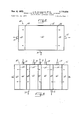
- FIG. 1 is a perspective view of a water treatment unit for use in conjunction with the present invention, partially cut away to show the interior details thereof;
- FIG. 2 is a simplified plan view of another water treatment unit that may be employed in accordance with the present invention.
- FIG. 3 is a simplified plan view of still another water treatment unit that may be employed in conjunction with the present invention:
- FIG. 4 is a flow chart illustrating the construction and operation of a system for use with a screen tube type of water treatment unit
- FIG. 5 is a perspective view of a screen tube-type water treatment unit, partially cut away to show the interior details thereof;
- FIG. 6 is a sectional perspective view of another screen tube unit that may be employed in conjunction with the present invention.
- FIG. 7 is a sectional perspective view of another screen tube unit that may be employed in conjunction with the present invention.
- FIG. 8 is a sectional perspective of still another screen tube unit that may be employed in conjunction with the present invention.
- FIG. 9 is a perspective view of another embodiment of a screen tube unit that may be employed in conjunction with the present invention, partially cut away to show the interior details thereof;
- FIG. 10 is a flow chart of an apparatus for treating water containing suspended solids from a sanitary system, embodying the features of the present invention.
- the screen should be made of a material that is capable of holding a coating of the suspended solids that are to be removed from the water. While a wide variety of screen materials may be employed, including natural and synthetic substances, the preferred materials for the screen are corrosion-resistant metals and synthetic organic polymers. Corrosion resistant metals must also show no interference with the treatment of water by the activated sludge process. Suitable corrosion resistant metals include aluminum and nickel, as well as such well known alloys as Monel (registered trademark of the International Nickel Company), an alloy of nickel and copper; and nickelchromium alloys such as Nichrome, Cambroloy, and Inconel (a trademark of the International Nickel Company). Inconel contains 15.5% chromium, 75% nickel, the balance being iron.
- Stainless steels may also be employed. Particularly preferred are types 302, 304, 305, and 316 stainless steels, although other stainless steels may also be suitably employed.
- suitable synthetic organic polymers include polyethylene, polypropylene, nylon, and Dacron, the preferred polymers being polyethylene and Dacron. Dacron is a trademark for a synthetic polyester fiber made from methyl terephthalate and ethylene glycol, and marketed by E. I. du Pont de Nemours & Company. In most applications, the metal screens are preferred because of their superior mechanical strength.
- the size of the openings in the screen should also be controlled within the proper range. If the openings are too small, the flow of water through the screen will be significantly hampered, and the screen will tend to become clogged. Thus, it is important that the openings be at least large enough to pass the majority of the suspended solids that are to be filtered from the liquid. On the other hand, it is important that the openings of the screen not be too large, since openings that are too large will hamper the ability of the screen to hold the solids coating. Of course, the screen openings must be adjusted to the particular process conditions encountered, including the volume of solids that can be tolerated in the efiluent stream, and the particle size and nature of the suspended solids. As a general matter, the openings should be in the range of about 10 to 100 microns. In the preferred embodiment, for most sanitary waste removal applications, a screen opening size in the range of about 50 to microns is preferred.
- the weave pattern of the screen is not critical. Suitable patterns that may be employed in the present invention include plain square, twilled square, plain Dutch, twilled Dutch, basket weave, etc.
- a plain square weave the size of the openings is easily calculated once the gauge (thickness) of the strands and the number of strands per centimeter are known. In this instance, the opening size is expressed in terms of the length of the square opening along one side.
- the size of the openings may be determined in accordance with the bubble test method set forth in S.A.E. Standard ARP-90l (April 1968).
- the directional components of the liquid containing the suspended solids parallel to the filter and through the filter must also be properly controlled in order to maintain the correct coating layer. Again, these variables must be adjusted to each individual situation, so that it is diflicult to generalize upon the optimum figures. However, it may generally be said that the directional component across the screen and coating layer should not be greater than about 10 feet per second, and preferably should not be greater than about 5 feet per second. In the case of most sanitary wastes, the directional component across the screen should be in the range of about 1 to 3 feet per second.
- the directional component through the screen and coating should, as a general matter, vary in the range of about 4 to 300 gallons per day per square foot of screen surface area.
- the directional component through the filter should be in the range of about 5 to 50 gallons per day per square foot of screen surface area.
- FIG. 1 shows a simple form of a Water treatment unit, generally indicated by reference numeral 10, which may be employed in the water treating method and apparatus of the present invention.
- the waste treatment apparatus 10 in this instance is designed to remove biodegradable impurities by an activated sludge process, followed by filtration.
- the waste treatment apparatus 10 comprises a tank 12, which is separated by a screen 14 into an influent compartment or zone 16 and an effluent compartment or zone 18.
- An inlet pipe 20 communicates with an upper portion of the influent zone 16, while an outlet pipe 22 communicates with an upper portion of the eflluent zone 18.
- the outlet pipe 22 should be positioned below the level of the inlet pipe 20 in order to build up a head differential across the screen 14 to allow liquid to flow from the infiuent zone 16 to the effluent zone 18.
- the infiuent zone 16 also forms an aeration chamber, and accordingly has suitable aeration means, in this instance defined by a cross pipe 24 and three down pipes 26, which are connected to horizontal air outlet pipes 28 at the bottom.
- Air is introduced into the water and suspended solids in the influent zone 16, producing a tumbling motion in the water as indicated by the arrows, so that there is a velocity component in the water parallel to the surface of the screen 14.
- a directional component through the screen 14 is produced by the difference in heads between the input zone 16 and the eflluent zone 18. It is preferred to locate the air outlet pipes 28 far enough from the screen 14 to avoid air scrubbing of the screen, which could cause partial removal of the coating layer.
- the tank 12 is shaped so that the efiluent zone 18 is narrower at the bottom than at the top in order to concentrate these solids.
- the solids are periodically returned to the influent zone 16 through a solids return pipe 30 having a pump 32, providing communication between the bottom of the effluent zone 18 and the influent zone 16.
- FIG. 2 shows a second apparatus constructed in accordance with the present invention, generally indicated by reference numeral 40.
- the apparatus 40 has a tank 42 which has four screens 44, forming an inner, rectangular influent zone 46 and an outer efiluent zone 48 around the perimeter of the tank. Water containing suspended solids is delivered to the influent zone 46 through an inlet pipe 50, and is removed from the eifiuent zones 48 through an outlet pipe 52.
- the embodiment of FIG. 2 has an air input system (not shown), which may be of conventional design such as that shown in FIG. 1.
- the air input system should be designed to produce a tumbling motion in the water in order to produce a directional component parallel to the surface of the screens 44.
- movement of water through the screens is produced by the difference in pressure head between the influent zone 46 and the effluent zone 48.
- FIG. 3 shows yet another embodiment of the present invention, wherein there are a plurality of screens, influent zones, and eflluent zones.
- This second modified apparatus is indicated generally by reference numeral 60.
- the apparatus 60 comprises a tank 62 having a plurality of vertical screens 64 separating the tank into a plurality of influent zones 66 and efiluent zones 68.
- Each influent zone 66 has an inlet pipe 70 communicating therewith, while each efiluent zone has an outlet pipe 72.
- the second modified apparatus 60 has means (not shown) for aerating the liquid and suspended solids in the influent zones 66, a well as means to produce a suitable directional component parallel to the screens surface.
- the operation of the water treatment units shown in FIGS. 1-3 is basically the same.
- the influent zone of the various apparatus will contain activated sludge, while solid material will be filtered out in passing the liquid from the influent zone to the eflluent zone.
- the operation of the unit is controlled by controlling the velocity of the liquid parallel to the screen and through the screen.
- the velocity parallel to the screen is a function of the speed at which the liquid is caused to tumble by the air injection, and this variable is therein the art.
- the apparatus shown in FIGS. 1 3 may be modified to pressurize the influent zone simply by covering the influent zone and providing an outlet valve for the air.
- the pressure within the influent zone could therefore be regulated by regulating the air pressure.
- the second general embodiment of the water treatment unit uses a tubular screen, referred to herein as a screen tube, instead of the planar screen shown in FIGS. 1-3.
- the screen tube separates the means that define the liquid filtration zone into an influent zone and an effluent zone.
- the influent zone may be defined by the interior of the tube, in which case the eflluent zone would be defined by the area surrounding the tube.
- this arrangement may be reversed, so that the area surrounding the tube constitutes the influent zone, while the interior of the tube forms the eflluent zone.
- FIG. 4 shows a suitable flow diagram for use in connection with the screen tube-type of embodiment shown in FIGS. 5-9.
- the water containing suspended wastes is delivered first to a conventional aeration chamber 80, where the liquid and suspended solids are aerated, preferably for the times previously set forth.
- the water and suspended solids are then transferred to a grit chamber 82, where readily settleable materials are removed. From that point, the water and suspended solids are delivered to a pump wet well 84 and then to a pump 86.
- the pump wet well 84 contains a sufficient amount of liquid to keep the pump 86 primed, so that an even flow to the screen tube unit is maintained.
- the water and suspended solids are delivered by the pump 86 to the influent zone defined by a screen tube unit 88.
- FIGS. 5-8 Various embodiments for such a screen tube unit 88 are shown in FIGS. 5-8, hereinafter discussed.
- a coating of solids is formed within the screen tube unit 88, and water is filtered through this coating, passing to the efiluent zone defined by the screen tube unit 88 to a filtered water outlet pipe 90, which delivers water to the rest of the system, as described in detail hereinafter.
- the remainder of the water, which will be concentrated in its solids content, passes out of the influent zone through a concentrate outlet pipe 92.
- the concentrate outlet pipe 92 has a pressure reduction valve 94 to maintain the proper pressure within the influent zone of the screen tube unit 88.
- the liquid, which has been concentrated in its suspended solids content, will ordinarily be returned to the aeration chamber through a recycle pipe 96 having a recycle valve 98.
- the water and suspended solids can optionally be returned to the pump wet well 84 by closing the recycle valve 98 and opening a pump wet well return valve 100 on the concentrate outlet pipe 92, which communicates back with the pump Wet well 84.
- the recycle of Water containing suspended solids through the pump wet Well 84 may be de-.
- FIGS. 5-8 show suitable screen tube units 88a.-88d for use in accordance with the present invention.
- the screen tlbe unit 88a comprises an outer encasing tube 102 and an internal screen tube 104.
- the screen tube 104 separates the unit into an influent zone 106, defined by the interior of the screen tube 104, and an efiluent zone 108 defined by the encasing tube 102 and the outside wall of the screen tube 104.
- Liquid containing suspended solids is delivered to the influent zone 106 through an inlet pipe 110 communicating with the interior of the screen tube 104.
- a coating is formed on the interior of the screen tube 104, and suspended solids are filtered from the liquid as it passes through the screen tube 104 into the efi'luent zone 108, and eventually to the filtered liquid outlet pipe 90, corresponding to the filtered liquid outlet pipe 90 shown in FIG. 4.
- the liquid that has not passed to the efiluent zone 108 will be concentrated in solids, and will pass through the concentrate outlet pipe 92.
- FIGS. 6-8 show modifications of the apparatus shown in FIG. 5.
- the encasing tube 102 has a plurality of screen tubes 112. This design will give a much larger screen surface area than would be given by a single screen tube 104 as shown in FIG. 5.
- a plurality of screen tubes 114 having a rectangular cross-sectional configuration is employed.
- FIG. 8 a plurality of concentric tubes is employed.
- This embodiment has a central screen tube 116 surrounded by a cylinder 118, which does not permit the passage of liquids.
- the cylinder 118 is surrounded by an outer screen tube 120, which, in turn, is surrounded by the encasing tube 102.
- the influent zone is formed by the interior of the central screen tube 116.
- a second influent zone is formed by the cylinder 118 and the outer screen tube 120.
- Efliuent zones are formed between the central screen tube 116 and the cylinder 118, and also between the outer screen tube 120 and the encasing tube 102.
- the operation of the screen tube units shown in FIGS. -8 is similar in principle to the operation of the water treatment apparatus shown in FIGS. 1-3.
- the directional component of the liquid and suspended solids parallel to the screen is controlled by the flow rate at which the liquid is paseed through the screen tube, and the directional component through the screen is controlled by pressure. These components should be controlled within the limits previously mentioned.
- FIGS. 5-8 may be modified to reverse the direction of liquid flow. That is, in the embodiment shown in FIG. 5, for example, liquid containing suspended solids could be delivered to the area between the screen tube 104 and the encasing tube 102, so that the influent and efiluent zones can be reversed.
- FIG. 9 shows yet another type of apparatus that may be constructed in accordance with the present invention.
- This embodiment employs a closed tank 124 having a pair of rotatable screen tubes 126 projecting into the interior thereof. Liquid containing suspended solids is delivered to the tank 124 through an inlet pipe 128, and a coating is formed on the screen tubes 126. Filtered liquid passes out of the tank through outlet pipes 130 communicating with the interior of the screen tubes 126. A velocity component parallel to the surface of the screen tubes 126 is obtained by rotating the screen tubes 126 within the liquid.
- each screen tube 126 is mounted for rotation, and has an external gear 131. These external gears 131 are driven by a drive gear 132, which, in turn, is connected to suitable drive means (not shown).
- suitable aeration means may be employed, such as an air inlet pipe 133, communicating with suitable air distributors (not shown) inside the tank 124.
- the tank 124 shown'in FIG. 9 is preferably fully enclosed, and has an air outlet pipe 134 having a pressure control valve 136 for controlling pressure within the tank 124.
- the pressure within the tank 124 controls the rate of flow of liquid through the screen tubes 126.
- the preferred use for the water treatment unit employed in the present invention is in connection with waste removal processes that use activated sludge.
- mixed liquor containing the activated sludge forms an excellent coating on the screen, effectively preventing significant amounts of suspended solids from being transferred to the efiluent zone. While this coating is found primarily on the upstream side, examination of the screen shows the growth of bacterial colonies within the interstices of the screen network, and even some growth on the downstream side.
- FIG. 10 illustrates an apparatus for treating water containing suspended solids from a sanitary system, constructed in accordance with the present invention.
- the water treatment unit as heretofore described, is indicated by reference numeral 140.
- Water from the sanitary system is delivered to the water treatment unit by a pump 142.
- the pump 142 draws water from an influent wet well 144.
- a level sensing device such as a float (not shown) in the influent wet well 144.
- the water containing suspended wastes is aerated by air delivered from a blower 146.
- a polymeric coagulant is delivered to the water before the water is delivered to the screen.
- This polymeric coagulant is stored in a polymer tank 148, and is delivered to the influent zone of the water treatment unit 140 by a pump 150.
- Suitable polymeric coagulants which may be employed are exceedingly well known in the art. Such coagulants are sold commercially by the Calgon Corporation, Pittsburgh, Pa., under the trade names Calgon WT-2660 and WT2870. These materials are described as viscous liquid, cationic polyelectrolytes. Suitable cationic polymers are also sold by Reichold Chemicals, Inc., White Plains, N.Y., under the trademark Aqua-Rid. These are described as water-miscible liquid cationic polyamine polyelectrolytes. Additional cationic polymers that may be employed are sold under the trade names Hercofloc 810, 814, and 828.1 by Hercules, Inc., Wilmington, Del. Finally, suitable cationic polymers are also marketed by Rohm & Haas Co. under the trade name Rohm & Haas C-7.
- Influent flow from the water treatment unit 140 is delivered to a filter wet well 152, and then via a pump 154 to a filter unit 156.
- the filter wet well 152 operates in the same manner as the influent wet well 144. That is, when the wet well 152 becomes full, a level sensing device actuates the pump 154, which empties the filter wct well 152 by pumping its contents to the filter unit 156.
- the filter unit 156 filters additional solids from the water which have passed through the screen in the water treatment unit 140.
- Any well known filter medium may be employed, and it is preferred that such filter medium be adequate to remove any visible particles from the water, i.e., particles having a diameter greater than about 0.5 micron.
- a particularly suitable filter unit is made up of three stages of paper filter elements having successively decreasing pore sizes of 5 microns, 3 microns, and 0.5 micron. Suitable paper filters are sold by the Hilliard Corporation, Elmira, N.Y., under the trade name Hilco.
- the water After being passed through the filter unit, the water will be optically clear.
- the water is next delivered to a chlorinator 158 of conventional design.
- the chlorinator 158 delivers chlorine to the water in order to destroy any harmful bacteria. Preferably, this chlorine should be delivered in an amount sufficient to produce a chlorine residual of about 1-2 milligrams per liter.
- the definition of the term chlorine residual is well known to those skilled in the art, and is discussed in Sawyer & McCarty, Chemistry for Sanitary Engineers, McGraw-Hill Book Company (2d ed.), chapter 21.
- Water is delivered from the chlorinator 158 to a storage tank 160, which stores sufficient treated water to insure a supply for the sanitary system during periods of peak demand. Water is delivered from the storage tank 160 back to the santitary system for use, as shown in FIG. 10.
- a water treatment system similar to that shown in FIG. 10 was constructed on board a ship.
- the water treatment unit was constructed in accordance with FIG. 2.
- the water treatment unit 140 had a volume of 1,530 gallons during normal operation, and had a capacity for an additional 417 gallons during periods of high through put.
- the minimum volume for proper aeration was 983 gallons.
- the unit was designed for a normal through put of 1000 gallons a day, with an aeration time in the influent zone of about .12 to 48 hours.
- the screens employed in the water treatment unit were made of type 316 stainless steel, had a plain square weave, and had openings of about 70 microns.
- the influent zone contained a mixed liquor which was primarily a fresh water suspension of activated sludge.
- Total mixed liquor suspended solids were in the range of about 2000 to 6000 mg./l. Flow rate through the screen was maintained at about 5-30 gal/square foot/day. Air was injected into the influent zone at a rate suflicient to produce a directional component of the liquid across the screen of about 2. to 2.5 feet per second.
- Treated water from the water treatment unit 140 as delivered to the filter wet well 152 which had a float-type level sensor, similar to that in the influent wet well 144.
- the filter wet well 152 had a maximum volume of 350 gallons, and a minimum volume of 95 gallons.
- the float level sensor indicated that the filter wet well 152 was full, it actuated a pump 154 to pump the water from the filter wet well 152 to a filter unit 156. The pump was shut off when the filter wet well reached its minimum volume of 95 gallons.
- the filter unit was made up of an assembly of three Hilco paper cartridge filters arranged in series. These filters had a successively decreasing pore diameter of microns, 3 microns, and 0.5 micron. Such a use of successive filters retards clogging of the filters with the smaller pore openings.
- the water was delivered to a commercially available chlorinator.
- the chlorinator used commercially available chlorination tablets, marketed under the trade name Sanuril by the Diamond Shamrock Corporation.
- Sufiicient chlorine was added to the water to provide a chlorine residual of 1 to 2 milligrams per liter.
- the water was delivered to a storage tank having a capacity of about 3000 gallons. From the storage tank, the water was delivered through a throttling pump to the existing sanitary system. The water as delivered to the storage tank was optically clear, i.e., had the appearance of pure water.
- a method for treating water containing suspended solids from a sanitary system comprising: aerating said water, delivering said water to a screen with a directional component across the screen surface and a directional component through said screen, said screen having openings large enough to pass the majority of said suspended solids, and said screen having the ability to hold a coating of said solids on the upstream side thereof; controlling the flow of said water containing said suspended solids so that a coating of said suspended solids is formed on said screen surface; continuing the delivery of said water containing suspended solids to said screen with a directional component across said screen and a directional component through said screen, whereby to filter solids from said water passing through said coating and screen; controlling the relationship between said directional components to maintain said coating on said screen, while continuing the delivery of water through said screen; storing said water after it has passed through said screen; and recycling said water to said sanitary system.
- a method for treating water containing suspended solids from a sanitary system comprising: aerating said water; delivering said water through a screen having openings large enough to pass a majority of said suspended solids, said openings being in the range from about 10 to microns with a directional component across said screen and a directional component through said screen, said directional component across said screen being no greater than about 10 feet per second, and said directional component through said screen being about 4 to 300 gallons per square foot per day, whereby to form a coating of said solids on said screen surface; continuing the delivery of said Water to said screen with said directional components across and through said screen, whereby to 1 1 filter solids from said water passing through said coating and screen; controlling the relationship between said directional components to maintain said coating on said screen; storing said water after it has passed through said screen; and recycling said water to said sanitary system.
Landscapes
- Life Sciences & Earth Sciences (AREA)
- Biodiversity & Conservation Biology (AREA)
- Microbiology (AREA)
- Hydrology & Water Resources (AREA)
- Engineering & Computer Science (AREA)
- Environmental & Geological Engineering (AREA)
- Water Supply & Treatment (AREA)
- Chemical & Material Sciences (AREA)
- Organic Chemistry (AREA)
- Filtration Of Liquid (AREA)
- Separation Of Suspended Particles By Flocculating Agents (AREA)
Applications Claiming Priority (1)
| Application Number | Priority Date | Filing Date | Title |
|---|---|---|---|
| US9797770A | 1970-12-14 | 1970-12-14 |
Publications (1)
| Publication Number | Publication Date |
|---|---|
| US3770624A true US3770624A (en) | 1973-11-06 |
Family
ID=22266021
Family Applications (1)
| Application Number | Title | Priority Date | Filing Date |
|---|---|---|---|
| US3770624D Expired - Lifetime US3770624A (en) | 1970-12-14 | 1970-12-14 | Method for treating water containing suspended solids from a sanitarysystem |
Country Status (5)
| Country | Link |
|---|---|
| US (1) | US3770624A (fr) |
| AU (1) | AU459688B2 (fr) |
| BE (1) | BE776610A (fr) |
| CA (1) | CA961181A (fr) |
| GB (1) | GB1360474A (fr) |
Cited By (8)
| Publication number | Priority date | Publication date | Assignee | Title |
|---|---|---|---|---|
| US3923657A (en) * | 1974-12-31 | 1975-12-02 | Kenneth F Roser | Combined septic tank inlet pipe sight glass end plug and tank aerator system |
| US3953328A (en) * | 1971-09-07 | 1976-04-27 | Aldag W | Separation of sludge |
| FR2387465A1 (fr) * | 1977-04-15 | 1978-11-10 | Lelievre Maurice | Predigesteurs-regulateur d'eaux-vannes et eaux usees domestiques pour stations d'epuration de maisons individuelles et de petites collectivites |
| US5407564A (en) * | 1993-01-25 | 1995-04-18 | Turf Industries, Inc. | Closed loop liquid treatment and recycling system |
| US6168712B1 (en) * | 1998-05-06 | 2001-01-02 | Kenko Sangyo Co., Ltd. | Apparatus for the biological treatment of waste fluid from the coating process |
| WO2003048053A1 (fr) * | 2001-12-03 | 2003-06-12 | Evac International Oy | Station d'epuration des eaux usees |
| US20060226071A1 (en) * | 2005-04-07 | 2006-10-12 | Mor-Air Inc. A Corporation Of State Of West Virginia | Aerobic sewage system |
| US20140124460A1 (en) * | 2011-04-05 | 2014-05-08 | Grundfos Holding A/S | Method and system for filtration and filtration cake layer formation |
Families Citing this family (1)
| Publication number | Priority date | Publication date | Assignee | Title |
|---|---|---|---|---|
| CN112675592A (zh) * | 2020-12-28 | 2021-04-20 | 孟祥林 | 一种观赏水循环系统前置液渣分离方法 |
-
1970
- 1970-12-14 US US3770624D patent/US3770624A/en not_active Expired - Lifetime
-
1971
- 1971-11-12 CA CA127,528A patent/CA961181A/en not_active Expired
- 1971-11-25 AU AU36168/71A patent/AU459688B2/en not_active Expired
- 1971-12-03 GB GB5631871A patent/GB1360474A/en not_active Expired
- 1971-12-13 BE BE776610A patent/BE776610A/fr unknown
Cited By (13)
| Publication number | Priority date | Publication date | Assignee | Title |
|---|---|---|---|---|
| US3953328A (en) * | 1971-09-07 | 1976-04-27 | Aldag W | Separation of sludge |
| US3923657A (en) * | 1974-12-31 | 1975-12-02 | Kenneth F Roser | Combined septic tank inlet pipe sight glass end plug and tank aerator system |
| FR2387465A1 (fr) * | 1977-04-15 | 1978-11-10 | Lelievre Maurice | Predigesteurs-regulateur d'eaux-vannes et eaux usees domestiques pour stations d'epuration de maisons individuelles et de petites collectivites |
| US5407564A (en) * | 1993-01-25 | 1995-04-18 | Turf Industries, Inc. | Closed loop liquid treatment and recycling system |
| US6168712B1 (en) * | 1998-05-06 | 2001-01-02 | Kenko Sangyo Co., Ltd. | Apparatus for the biological treatment of waste fluid from the coating process |
| US20050103696A1 (en) * | 2001-12-03 | 2005-05-19 | Evac International Oy | Sewage treatment plant |
| WO2003048053A1 (fr) * | 2001-12-03 | 2003-06-12 | Evac International Oy | Station d'epuration des eaux usees |
| US7077958B2 (en) | 2001-12-03 | 2006-07-18 | Evac International Oy | Sewage treatment plant |
| US20060226071A1 (en) * | 2005-04-07 | 2006-10-12 | Mor-Air Inc. A Corporation Of State Of West Virginia | Aerobic sewage system |
| US7413656B2 (en) * | 2005-04-07 | 2008-08-19 | Mor-Air Inc. | Aerobic sewage system |
| US20140124460A1 (en) * | 2011-04-05 | 2014-05-08 | Grundfos Holding A/S | Method and system for filtration and filtration cake layer formation |
| US9868079B2 (en) | 2011-04-05 | 2018-01-16 | Grudfos Holding A/S | Method and system for filtration and filtration cake layer formation |
| US10486089B2 (en) * | 2011-04-05 | 2019-11-26 | Grundfos Holding A/S | Method and system for filtration and filtration cake layer formation |
Also Published As
| Publication number | Publication date |
|---|---|
| GB1360474A (en) | 1974-07-17 |
| AU3616871A (en) | 1973-05-31 |
| CA961181A (en) | 1975-01-14 |
| AU459688B2 (en) | 1975-04-10 |
| BE776610A (fr) | 1972-04-04 |
Similar Documents
| Publication | Publication Date | Title |
|---|---|---|
| US3764525A (en) | Method for removing suspended solids from liquids | |
| US4071445A (en) | Method and apparatus for treating waste water on ships | |
| US4427551A (en) | Solids separation and liquid clarification system | |
| US4250040A (en) | Method for purifying septic tank effluent | |
| US3713543A (en) | Activated sewage plant | |
| US6051137A (en) | Sewage dewatering process and equipment | |
| US3956128A (en) | Apparatus for treating industrial and domestic waste waters | |
| US4104166A (en) | Apparatus for purifying septic tank effluent | |
| US5112483A (en) | Slow sand/nanofiltration water treatment system | |
| US5928514A (en) | On board treatment system | |
| US3968034A (en) | Process and apparatus for treating wastes by a combined activated sludge and biological filter bed | |
| FI103275B (fi) | Menetelmä ja laitteisto jätevesien puhdistamiseksi biologisesti | |
| WO2012019294A1 (fr) | Bioréacteur à membrane avec lit mobile | |
| US3846305A (en) | Apparatus for the filtration and biological purification of contaminated water | |
| US3825119A (en) | Waste water treatment unit | |
| US3459302A (en) | Apparatus and method of filtering solids from a liquid effluent | |
| US3807565A (en) | Sewage disposal system | |
| GB2272171A (en) | Treatment of effluents | |
| USRE28458E (en) | Apparatus and method of filtering solids from a liquid effluent | |
| US3928190A (en) | Method of biological purification of sewage | |
| US3408288A (en) | Industrial waste water treatment apparatus and method | |
| US3850808A (en) | A wastewater treatment system | |
| US4069156A (en) | Sewage treatment system | |
| US3482695A (en) | Package water treatment plant | |
| US3899423A (en) | Sewage treatment system |
Legal Events
| Date | Code | Title | Description |
|---|---|---|---|
| AS | Assignment |
Owner name: SMITH & LOVERLESS, INC., A CORP. OF KS. Free format text: ASSIGNMENT OF ASSIGNORS INTEREST.;ASSIGNOR:ECODYNE CORPORATION;REEL/FRAME:003924/0764 Effective date: 19811008 |
|
| AS | Assignment |
Owner name: MARINE MIDLAND BUSINESS LOANS, INC., MISSOURI Free format text: SECURITY INTEREST;ASSIGNOR:SMITH & LOVELESS, INC.;REEL/FRAME:005317/0138 Effective date: 19900401 |
|
| AS | Assignment |
Owner name: BOATMEN S NATIONAL BANK OF ST. LOUIS, THE A NAT Free format text: SECURITY INTEREST;ASSIGNOR:SMITH & LOVELESS, INC. A CORP. OF KANSAS;REEL/FRAME:006024/0068 Effective date: 19920212 Owner name: SMITH & LOVELOSS INC. Free format text: RELEASE BY SECURED PARTY OF SECURITY AGREEMENT RECORDED AT REEL 5317 FRAME 138.;ASSIGNOR:MARINE MIDLAND BUSINESS LOANS, INC.;REEL/FRAME:006032/0076 Effective date: 19920212 |