US3801845A - Rotational characteristics sensing and signal generating mechanism and a magnetic field interrupter therefor - Google Patents
Rotational characteristics sensing and signal generating mechanism and a magnetic field interrupter therefor Download PDFInfo
- Publication number
- US3801845A US3801845A US00271249A US3801845DA US3801845A US 3801845 A US3801845 A US 3801845A US 00271249 A US00271249 A US 00271249A US 3801845D A US3801845D A US 3801845DA US 3801845 A US3801845 A US 3801845A
- Authority
- US
- United States
- Prior art keywords
- hub
- magnetic field
- frusto
- probe
- interrupter
- Prior art date
- Legal status (The legal status is an assumption and is not a legal conclusion. Google has not performed a legal analysis and makes no representation as to the accuracy of the status listed.)
- Expired - Lifetime
Links
- 230000007246 mechanism Effects 0.000 title claims description 17
- 239000000523 sample Substances 0.000 claims abstract description 24
- 230000002093 peripheral effect Effects 0.000 claims description 10
- 238000009434 installation Methods 0.000 claims description 5
- 230000001133 acceleration Effects 0.000 abstract description 4
- 239000000463 material Substances 0.000 abstract description 3
- 238000010276 construction Methods 0.000 description 2
- 229910000639 Spring steel Inorganic materials 0.000 description 1
- 238000003754 machining Methods 0.000 description 1
- 238000004519 manufacturing process Methods 0.000 description 1
- 230000004048 modification Effects 0.000 description 1
- 238000012986 modification Methods 0.000 description 1
Images
Classifications
-
- G—PHYSICS
- G01—MEASURING; TESTING
- G01P—MEASURING LINEAR OR ANGULAR SPEED, ACCELERATION, DECELERATION, OR SHOCK; INDICATING PRESENCE, ABSENCE, OR DIRECTION, OF MOVEMENT
- G01P3/00—Measuring linear or angular speed; Measuring differences of linear or angular speeds
- G01P3/42—Devices characterised by the use of electric or magnetic means
- G01P3/44—Devices characterised by the use of electric or magnetic means for measuring angular speed
- G01P3/48—Devices characterised by the use of electric or magnetic means for measuring angular speed by measuring frequency of generated current or voltage
- G01P3/481—Devices characterised by the use of electric or magnetic means for measuring angular speed by measuring frequency of generated current or voltage of pulse signals
- G01P3/488—Devices characterised by the use of electric or magnetic means for measuring angular speed by measuring frequency of generated current or voltage of pulse signals delivered by variable reluctance detectors
-
- B—PERFORMING OPERATIONS; TRANSPORTING
- B60—VEHICLES IN GENERAL
- B60T—VEHICLE BRAKE CONTROL SYSTEMS OR PARTS THEREOF; BRAKE CONTROL SYSTEMS OR PARTS THEREOF, IN GENERAL; ARRANGEMENT OF BRAKING ELEMENTS ON VEHICLES IN GENERAL; PORTABLE DEVICES FOR PREVENTING UNWANTED MOVEMENT OF VEHICLES; VEHICLE MODIFICATIONS TO FACILITATE COOLING OF BRAKES
- B60T8/00—Arrangements for adjusting wheel-braking force to meet varying vehicular or ground-surface conditions, e.g. limiting or varying distribution of braking force
- B60T8/32—Arrangements for adjusting wheel-braking force to meet varying vehicular or ground-surface conditions, e.g. limiting or varying distribution of braking force responsive to a speed condition, e.g. acceleration or deceleration
- B60T8/321—Arrangements for adjusting wheel-braking force to meet varying vehicular or ground-surface conditions, e.g. limiting or varying distribution of braking force responsive to a speed condition, e.g. acceleration or deceleration deceleration
- B60T8/329—Systems characterised by their speed sensor arrangements
-
- H—ELECTRICITY
- H02—GENERATION; CONVERSION OR DISTRIBUTION OF ELECTRIC POWER
- H02K—DYNAMO-ELECTRIC MACHINES
- H02K19/00—Synchronous motors or generators
- H02K19/16—Synchronous generators
- H02K19/22—Synchronous generators having windings each turn of which co-operates alternately with poles of opposite polarity, e.g. heteropolar generators
- H02K19/24—Synchronous generators having windings each turn of which co-operates alternately with poles of opposite polarity, e.g. heteropolar generators with variable-reluctance soft-iron rotors without winding
Definitions
- ABSTRACT A vehicle wheel hub is provided with a frusto-conical [22] filed July 1972 end surface having a shoulder adjacent the smaller cir- [21] App]. No.: 271,249 cumferential side.
- a magnetic field probe is mounted I in radially spaced relation to the frusto-conical surf face, and an elastic garter member made of a mag i y gg v netic field modifying material is positioned on the 169 170 frusto-conical surface.
- the garter member has a plu- 0 care 310/73 75/) 363/20 rality of raised surfaces which, when rotating with the hub relative to the probe, interrupts the magnetic field sensed by the probe so that signals which reflect the I References cued rotational characteristics of the hub are generated in UNITED STATES PATENTS the probe.
- the signals may be related to hub rota- 3,626,228 12/1971 Jordan 310/168 tional velocity or hub acceleration characteristics, for 3,549,925 12/1970 Johnson... 310/168 example. 3,551,712 12/1970 Jones 310/168 3,626,223 12/1971 Maier...
- the invention relates to a magnetic field interrupter and to a rotational characteristics signal generating mechanism of which the magnetic field interrupter is a part. In many systems it is required to determine certain rotational characteristics of a rotatable element and to develop signal reflecting these characteristics in order to control the rotation of the rotatable element and/or other elements to which the system is connected.
- a typical example of such a system is a wheel lock control in which the velocity or acceleration characteristics of a vehicle wheel are sensed and corresponding signals are generated so that the brake for the wheel is in turn controlled to prevent the wheel from locking during heavy braking.
- Such systems are well known in the art and are exemplified by that disclosed in US. Pat. No. 3,554,612.
- One of the more common mechanisms utilized to develop the necessary rotational characteristics signals is a magnetic field probe mounted with its sensing head closely spaced from teeth-like elements provided on a suitable part of the rotatable wheel assembly.
- the teeth-like elements are usually provided as a gear, the teeth being machined, stamped, or cast as a part of the wheel hub or a separate disc, attached to the rotatable wheel in such a manner that the teeth interrupt the magnetic field sensed by the probe as the wheel rotates.
- a gear Such a device is exemplified by that found in the disclosure of US. Pat. No. 3,619,680.
- wheel lock control systems are often provided on a small number of vehicles compared to the total production, it is common to provide a separate toothed disc'as an interrupter, which must be bolted or otherwise suitably secured to a portion of the rotatable wheel assembly, or some portion of the rotating wheel assembly such as a wheel hub must be provided with such teeth whether or not a wheel lock control system is to be installed on the parwheel hub part for all like vehicles whether or not a magnetic field interrupter is required. It does not require the relatively expensive machining of gear-like teeth and does not require extensive installation such as that necessary when a separate toothed disc must be bolted in place.
- the end of the hub adjacent the bolts mounting the brake unit backing plate to the axle housing is normally formed to insure rotational clearance. It is in this area that a frusto-conical surface is provided on the wheel hub, with the smaller'peripheral edge extending toward the hub end and terminating at a shoulder which is larger in its outer diameter than the smaller peripheral edge of the frusto-conical surface, and is preferably smaller in its outer diameter than the larger peripheral edge of the frusto-conical surface. Only when the vehicle of which the hub is a part is to have a rotational characteristics sensing mechanism as a part of a system such as a wheel lock control system is the magnetic field interrupter embodying the invention installed.
- This interrupter is an elastic garter member which has a plurality of teeth-like generallyradial extensions and depressions substantially equally spaced c'ircumferentially about it.
- the garter member is received on the hub so as to move rotatably with the hub adjacent the magnetic field probe head of the sensing mechanism. As each tooth-like projection or extension rotates immediately past the probe head, the magnetic field sensed by the probe is modified and suitable rotational characteristics signals are generated. While it is preferable to have a frusto-conical surface and a similar frusto-conical interrupter garter member, in some installations it may be more desirable to have the surface and garter member of a somewhat different peripheral configuration, such as a cylindrical. configuration.
- the advantage of a frusto-conical arrangement, particularly with the end shoulder being of an outer diameter which is intermediate the diameters of the frusto-conical peripheral edges, includes the ease of installation of the garter member. It need only be positioned generally adjacent the end of the hub and moved axially so that it expands radially to the extent necessary to pass over the shoulder. It will then contract radially to grip the frusto-conical hub surface so that it is immediately locked in position with the smaller peripheral edge located at the shoulder over which the garter member has passed.
- the garter member may be made of any suitable magnetic field modifying material, such as spring steel, and must have sufficient tension so that in its contracting condition it grips the hub tightly to rotate therewith as the hub rotates.
- the garter member may be made in an accordian-like fashion with the teeth thereof having rounded edges or squared-off edges, depending upon the characteristics needed to generate signals in accordance with the sensing of the probe.
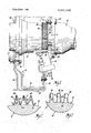
- FIG. 1 is a cross-section view, with parts broken away, illustrating a mechanism embodying the invention.
- FIG. 2 is a partial-section view taken in the direction of arrows 22 of FIG. 1 and showing an enlarged section of the interrupter and its relationship to the hub.
- FIG. 3 shows a modified tooth-like construction of the interrupter.
- a vehicle axle housing 10 is suitably fixed to the vehicle of which the mechanism is a part and has an axle 12 extending there-.
- the axle is arranged to drive or permit rotation of the hub 14 relative to the axle housing 10. If, for example, the wheel assembly 16, of which hub 14 is a part, is a driven wheel assembly, axle 12 is suitably connected to the hub 14 to transmit driving forces thereto. If the wheel assembly 16 is not a driving wheel, suitable bearings may be provided so that the hub 14 can rotate on axle 12.
- the wheel assembly 16 includes a wheel 18 and a brake drum 20 which are secured by suitable bolts 22 to the flange 24 of the hub. If another type of brake, such as a disc brake, is used, a suitable disc would be provided instead of the drum 20.
- the brake assembly for the wheel assembly 16 also includes a backing plate or support member 26 which is secured to the flange 28 of the axle housing 10 by suitable bolts 30.
- suitable brake shoes and actuating mechanisms for them are mounted on the backing plate 26 so as to engage the shoe linings with the friction surface 32 of the drum 20.
- the particular brake arrangement utilized forms no part of the invention,-the other brake elements have been omitted for simplicity and clarity.
- a magnetic field probe 34 is suitably mounted on backing plate 26 by bracket 36.
- the probe or sensor has a head 38 which extends to a point radially outward from but immediately adjacent the hub inner end 40.
- the sensing mechanism s body 42 extends through an opening 44 of the backing plate 26 so as to be properly positioned.
- the terminals'46 on the other end of the sensing mechanism 34 provide suitable connections to a wheel lock control system, for example, so that signalsgenerated in the sensing mechanism are transmitted thereto.
- the hub inner end 40 has a shoulder 48 formed thereon adjacent the hub end surface 50.
- the shoulder extends radially outwardly so that the side thereof oppositehub end surface 50 is of somewhat greater diameter than the hub outer surface at this point.
- a smooth hub outer surface 52 is formed on the hub and in accordance with the preferred embodiment of the invention, is frusto-conical so that the smaller diameter edge 54 is adjacent the edge of shoulder 48 and is of lesser diameter than the shoulder.
- the larger diameter edge 56 of surface 52 is positioned axially toward the hub flange 24 from the hub shoulder 48 and is preferably of greater diameter than the maximum diameter of shoulder 48.
- the magnetic field interrupter 58 is an elastic garter member having a plurality of tooth-like projections formed thereon extending generally axially of the gar ter member.
- the interrupter-58 is also frusto-conical and has a smaller diameter edge 60 and a larger diameter edge 62.
- the tooth-like projections 64 hereinafter referred to as teeth, are formed as a part of the body of the garter member by a series of folds. Thus, the teeth 64 are separated by depressions 66 which extend radially inwardly. In the embodiment shown in FIGS. 1 and 2, the teeth 64 have rounded points or edges 68, as do the depressions 66.
- the rounded points or edges 70 formed by the depressions 66 extend radially inward.
- the rounded points or edges of each adjacent tooth and depression are joined by sides 72, which may be straight or flat surfaces.
- the teeth are squared-off at their radially outer ends 74 and a similar construction of the depressions 66 provides squared-off radially inwardly positioned points or edges 76.
- the elastic garter member 58 When a magnetic field interrupter is required on the vehicle hub, the elastic garter member 58 is installed on the hub end 40 by moving it axially over shoulder 48, the elastic characteristics of the garter member permitting it to expand radially for this purpose. The garter member is then radially contracted due to its elasticity as soon as it clears the outer periphery of shoulder 48 and the garter member smaller diameter edge 60 positions itself at the inner edge of shoulder 48. The garter member has sufficient radial contractual elasticity to firmly grip the hub surface 52 so that the garter member will rotate with the hub. The depression points or edges or 76 engage surfaces 52 for this purpose.
- Such signals may relate to the rotational velocity of the hub or its acceleration characterisitcs, or
- the signals may be used to measure vehicle speed in a speedometer arrangement, or to measure the specific changes in the rotational characteristics of the wheel assembly 16 during braking so as to control the wheel brake mechanism to maintain a desired'amount of wheel braking without locking the wheels during very heavy braking.
- a rotatable wheel hub having a frusto-conical outer surface formed adjacent one end thereof and an integrally formed shoulder at the smaller diameter peripheral edge of said frusto-conical outer surface
Landscapes
- Engineering & Computer Science (AREA)
- Physics & Mathematics (AREA)
- General Physics & Mathematics (AREA)
- Power Engineering (AREA)
- Transportation (AREA)
- Mechanical Engineering (AREA)
- Regulating Braking Force (AREA)
Abstract
A vehicle wheel hub is provided with a frusto-conical end surface having a shoulder adjacent the smaller circumferential side. A magnetic field probe is mounted in radially spaced relation to the frusto-conical surface, and an elastic garter member made of a magnetic field modifying material is positioned on the frusto-conical surface. The garter member has a plurality of raised surfaces which, when rotating with the hub relative to the probe, interrupts the magnetic field sensed by the probe so that signals which reflect the rotational characteristics of the hub are generated in the probe. The signals may be related to hub rotational velocity or hub acceleration characteristics, for example.
Description
United States Patent [191- Gavitt, Sr. [4 1 Apr. 2, 1974 4] ROTATIONAL CHARACTERISTICS 3,694,661 9/1972 Minova 310/168 SENSING AND SIGNAL GENERATING 3,573,520 4/1971 Dorshimer 310/168 MECHANISM AND A MAGNETIC FIELD INTERRUPTER THEREFOR Primary Examiner-K k y [75] Inventor: Willis A. Gavitt, Sr., Ionia, Mich. Attorney Agent or Funk-D MCGraw [73] Assignee: General Motors Corporation,
Detroit, Mich. [57] ABSTRACT A vehicle wheel hub is provided with a frusto-conical [22] filed July 1972 end surface having a shoulder adjacent the smaller cir- [21] App]. No.: 271,249 cumferential side. A magnetic field probe is mounted I in radially spaced relation to the frusto-conical surf face, and an elastic garter member made of a mag i y gg v netic field modifying material is positioned on the 169 170 frusto-conical surface. The garter member has a plu- 0 care 310/73 75/) 363/20 rality of raised surfaces which, when rotating with the hub relative to the probe, interrupts the magnetic field sensed by the probe so that signals which reflect the I References cued rotational characteristics of the hub are generated in UNITED STATES PATENTS the probe. The signals may be related to hub rota- 3,626,228 12/1971 Jordan 310/168 tional velocity or hub acceleration characteristics, for 3,549,925 12/1970 Johnson... 310/168 example. 3,551,712 12/1970 Jones 310/168 3,626,223 12/1971 Maier... 310/168 1 Claim, 3 Drawing Figures ROTATIONAL CHARACTERISTICS SENSING AND SIGNAL GENERATING MECHANISM AND A MAGNETIC FIELD INTERRUPTER THEREFOR The invention relates to a magnetic field interrupter and to a rotational characteristics signal generating mechanism of which the magnetic field interrupter is a part. In many systems it is required to determine certain rotational characteristics of a rotatable element and to develop signal reflecting these characteristics in order to control the rotation of the rotatable element and/or other elements to which the system is connected. A typical example of such a system is a wheel lock control in which the velocity or acceleration characteristics of a vehicle wheel are sensed and corresponding signals are generated so that the brake for the wheel is in turn controlled to prevent the wheel from locking during heavy braking. Such systems are well known in the art and are exemplified by that disclosed in US. Pat. No. 3,554,612. One of the more common mechanisms utilized to develop the necessary rotational characteristics signals is a magnetic field probe mounted with its sensing head closely spaced from teeth-like elements provided on a suitable part of the rotatable wheel assembly. The teeth-like elements are usually provided as a gear, the teeth being machined, stamped, or cast as a part of the wheel hub or a separate disc, attached to the rotatable wheel in such a manner that the teeth interrupt the magnetic field sensed by the probe as the wheel rotates. Such a device is exemplified by that found in the disclosure of US. Pat. No. 3,619,680. Since wheel lock control systems, as well as other systems utilizing rotatable characteristics signals, are often provided on a small number of vehicles compared to the total production, it is common to provide a separate toothed disc'as an interrupter, which must be bolted or otherwise suitably secured to a portion of the rotatable wheel assembly, or some portion of the rotating wheel assembly such as a wheel hub must be provided with such teeth whether or not a wheel lock control system is to be installed on the parwheel hub part for all like vehicles whether or not a magnetic field interrupter is required. It does not require the relatively expensive machining of gear-like teeth and does not require extensive installation such as that necessary when a separate toothed disc must be bolted in place. The end of the hub adjacent the bolts mounting the brake unit backing plate to the axle housing is normally formed to insure rotational clearance. It is in this area that a frusto-conical surface is provided on the wheel hub, with the smaller'peripheral edge extending toward the hub end and terminating at a shoulder which is larger in its outer diameter than the smaller peripheral edge of the frusto-conical surface, and is preferably smaller in its outer diameter than the larger peripheral edge of the frusto-conical surface. Only when the vehicle of which the hub is a part is to have a rotational characteristics sensing mechanism as a part of a system such as a wheel lock control system is the magnetic field interrupter embodying the invention installed. This interrupter is an elastic garter member which has a plurality of teeth-like generallyradial extensions and depressions substantially equally spaced c'ircumferentially about it. The garter member is received on the hub so as to move rotatably with the hub adjacent the magnetic field probe head of the sensing mechanism. As each tooth-like projection or extension rotates immediately past the probe head, the magnetic field sensed by the probe is modified and suitable rotational characteristics signals are generated. While it is preferable to have a frusto-conical surface and a similar frusto-conical interrupter garter member, in some installations it may be more desirable to have the surface and garter member of a somewhat different peripheral configuration, such as a cylindrical. configuration. The advantage of a frusto-conical arrangement, particularly with the end shoulder being of an outer diameter which is intermediate the diameters of the frusto-conical peripheral edges, includes the ease of installation of the garter member. It need only be positioned generally adjacent the end of the hub and moved axially so that it expands radially to the extent necessary to pass over the shoulder. It will then contract radially to grip the frusto-conical hub surface so that it is immediately locked in position with the smaller peripheral edge located at the shoulder over which the garter member has passed. The garter member may be made of any suitable magnetic field modifying material, such as spring steel, and must have sufficient tension so that in its contracting condition it grips the hub tightly to rotate therewith as the hub rotates. The garter member may be made in an accordian-like fashion with the teeth thereof having rounded edges or squared-off edges, depending upon the characteristics needed to generate signals in accordance with the sensing of the probe.
IN THE DRAWING FIG. 1 is a cross-section view, with parts broken away, illustrating a mechanism embodying the invention.
FIG. 2 is a partial-section view taken in the direction of arrows 22 of FIG. 1 and showing an enlarged section of the interrupter and its relationship to the hub.
FIG. 3 shows a modified tooth-like construction of the interrupter.
In the mechanism shown in FIG. 1, a vehicle axle housing 10 is suitably fixed to the vehicle of which the mechanism is a part and has an axle 12 extending there-.
through. The axle is arranged to drive or permit rotation of the hub 14 relative to the axle housing 10. If, for example, the wheel assembly 16, of which hub 14 is a part, is a driven wheel assembly, axle 12 is suitably connected to the hub 14 to transmit driving forces thereto. If the wheel assembly 16 is not a driving wheel, suitable bearings may be provided so that the hub 14 can rotate on axle 12. The wheel assembly 16 includes a wheel 18 and a brake drum 20 which are secured by suitable bolts 22 to the flange 24 of the hub. If another type of brake, such as a disc brake, is used, a suitable disc would be provided instead of the drum 20. The brake assembly for the wheel assembly 16 also includes a backing plate or support member 26 which is secured to the flange 28 of the axle housing 10 by suitable bolts 30. As is well known in the brake art, suitable brake shoes and actuating mechanisms for them are mounted on the backing plate 26 so as to engage the shoe linings with the friction surface 32 of the drum 20. However, since the particular brake arrangement utilized forms no part of the invention,-the other brake elements have been omitted for simplicity and clarity.
A magnetic field probe 34 is suitably mounted on backing plate 26 by bracket 36. The probe or sensor has a head 38 which extends to a point radially outward from but immediately adjacent the hub inner end 40. The sensing mechanism s body 42 extends through an opening 44 of the backing plate 26 so as to be properly positioned. The terminals'46 on the other end of the sensing mechanism 34 provide suitable connections to a wheel lock control system, for example, so that signalsgenerated in the sensing mechanism are transmitted thereto.
The hub inner end 40 has a shoulder 48 formed thereon adjacent the hub end surface 50. The shoulder extends radially outwardly so that the side thereof oppositehub end surface 50 is of somewhat greater diameter than the hub outer surface at this point. A smooth hub outer surface 52 is formed on the hub and in accordance with the preferred embodiment of the invention, is frusto-conical so that the smaller diameter edge 54 is adjacent the edge of shoulder 48 and is of lesser diameter than the shoulder. The larger diameter edge 56 of surface 52 is positioned axially toward the hub flange 24 from the hub shoulder 48 and is preferably of greater diameter than the maximum diameter of shoulder 48.
The magnetic field interrupter 58 is an elastic garter member having a plurality of tooth-like projections formed thereon extending generally axially of the gar ter member. In the preferred embodiment in which the hub surface 52 is frusto-conical, the interrupter-58 is also frusto-conical and has a smaller diameter edge 60 and a larger diameter edge 62. The tooth-like projections 64, hereinafter referred to as teeth, are formed as a part of the body of the garter member by a series of folds. Thus, the teeth 64 are separated by depressions 66 which extend radially inwardly. In the embodiment shown in FIGS. 1 and 2, the teeth 64 have rounded points or edges 68, as do the depressions 66. The rounded points or edges 70 formed by the depressions 66 extend radially inward. The rounded points or edges of each adjacent tooth and depression are joined by sides 72, which may be straight or flat surfaces. In the modification shown in FIG. 3, the teeth are squared-off at their radially outer ends 74 and a similar construction of the depressions 66 provides squared-off radially inwardly positioned points or edges 76.
When a magnetic field interrupter is required on the vehicle hub, the elastic garter member 58 is installed on the hub end 40 by moving it axially over shoulder 48, the elastic characteristics of the garter member permitting it to expand radially for this purpose. The garter member is then radially contracted due to its elasticity as soon as it clears the outer periphery of shoulder 48 and the garter member smaller diameter edge 60 positions itself at the inner edge of shoulder 48. The garter member has sufficient radial contractual elasticity to firmly grip the hub surface 52 so that the garter member will rotate with the hub. The depression points or edges or 76 engage surfaces 52 for this purpose. If the hub and its garter member rotate, the teeth 64 pass immediately adjacent the probe head 38, modifying the magnetic field sensed by the probe and causing suitable rotational characteristics signals to be generated. Such signals, for example, may relate to the rotational velocity of the hub or its acceleration characterisitcs, or
both. The signals may be used to measure vehicle speed in a speedometer arrangement, or to measure the specific changes in the rotational characteristics of the wheel assembly 16 during braking so as to control the wheel brake mechanism to maintain a desired'amount of wheel braking without locking the wheels during very heavy braking.
What is claimed is:
1. In combination in a rotational characteristics signal generating mechanism,
a rotatable wheel hub having a frusto-conical outer surface formed adjacent one end thereof and an integrally formed shoulder at the smaller diameter peripheral edge of said frusto-conical outer surface,
magnetic field probe mounted with the head thereof spaced radially outward of said frusto conical outer surface, and an annular frustoconical magnetic field interrupter formed as a multi-toothed garter member received on said frustoconical outer surface of said hub immediately adjacent said magnetic field probe head with the interrupter smaller diameter peripheral edge thereof engaging said shoulder, said interrupter being sufficiently elastic to stretch over said shoulder during installation and retract radially to elastically grip' netic field sensed by said probe in accordance with said rotation.
Claims (1)
1. In combination in a rotational characteristics signal generating mechanism, a rotatable wheel hub having a frusto-conical outer surface formed adjacent one end thereof and an integrally formed shoulder at the smaller diameter peripheral edge of said frusto-conical outer surface, a magnetic field probe mounted with the head thereof spaced radially outward of said frusto-conical outer surface, and an annular frusto-conical magnetic field interrupter formed as a multi-toothed garter member received on said frusto-conical outer surface of said hub immediately adjacent said magnetic field probe head with the interrupter smaller diameter peripheral edge thereof engaging said shoulder, said interrupter being sufficiently elastic to stretch over said shoulder during installation and retract radially to elastically grip said frusto-conical outer surface, said interrupter rotating with said hub and interrupting the magnetic field sensed by said probe in accordance with said rotation.
Applications Claiming Priority (1)
| Application Number | Priority Date | Filing Date | Title |
|---|---|---|---|
| US27124972A | 1972-07-13 | 1972-07-13 |
Publications (1)
| Publication Number | Publication Date |
|---|---|
| US3801845A true US3801845A (en) | 1974-04-02 |
Family
ID=23034805
Family Applications (1)
| Application Number | Title | Priority Date | Filing Date |
|---|---|---|---|
| US00271249A Expired - Lifetime US3801845A (en) | 1972-07-13 | 1972-07-13 | Rotational characteristics sensing and signal generating mechanism and a magnetic field interrupter therefor |
Country Status (1)
| Country | Link |
|---|---|
| US (1) | US3801845A (en) |
Cited By (13)
| Publication number | Priority date | Publication date | Assignee | Title |
|---|---|---|---|---|
| US3927339A (en) * | 1971-12-07 | 1975-12-16 | Daimler Benz Ag | Frequency transmitters for producing control signals controlling the brake force in motor vehicle wheels |
| US3961215A (en) * | 1973-12-26 | 1976-06-01 | Eaton Corporation | Rotor for wheel speed sensor assembly |
| FR2311695A1 (en) * | 1975-05-07 | 1976-12-17 | Rockwell International Corp | WHEEL SPEED SENSOR FOR VEHICLE DRIVE AXLE AND ITS APPLICATION TO AN ANTI-LOCK BRAKING CIRCUIT |
| USRE30522E (en) * | 1973-12-26 | 1981-02-17 | Eaton Corporation | Rotor for wheel speed sensor assembly |
| EP0137270A3 (en) * | 1983-09-28 | 1985-06-12 | Werkzeugmaschinenfabrik Oerlikon-Buhrle Ag | |
| EP0188668A1 (en) * | 1985-01-22 | 1986-07-30 | Toyota Jidosha Kabushiki Kaisha | Pulse gear for rotor sensor |
| EP0205763A1 (en) * | 1985-06-15 | 1986-12-30 | WABCO Westinghouse Fahrzeugbremsen GmbH | Apparatus for sensing the speed and/or angle-of-rotation signals of a jointed shaft |
| EP0251009A1 (en) * | 1986-07-02 | 1988-01-07 | Siemens Aktiengesellschaft | Wheel for an angular pulse generator |
| US4916390A (en) * | 1986-10-03 | 1990-04-10 | Wabco Westinghouse Fahrzeugbremsen Gmbh | Coil spring toothed wheel for use in measuring an angular velocity |
| US5053656A (en) * | 1989-12-18 | 1991-10-01 | Ina Bearing Company, Inc. | Sensing ring for rotational sensing system |
| US5085519A (en) * | 1991-07-05 | 1992-02-04 | The Timken Company | Bearing assembly with speed sensor and process for assembling the same |
| FR2689703A1 (en) * | 1990-09-26 | 1993-10-08 | Connell James | Rotating iron alternator. |
| US5696442A (en) * | 1996-07-19 | 1997-12-09 | General Motors Corporation | Rotational velocity sensor ring apparatus and method |
Citations (6)
| Publication number | Priority date | Publication date | Assignee | Title |
|---|---|---|---|---|
| US3549925A (en) * | 1969-02-05 | 1970-12-22 | Kelsey Hayes Co | Alternating current generator |
| US3551712A (en) * | 1968-07-25 | 1970-12-29 | Kelsey Hayes Co | Sensor with flexible coupling |
| US3573520A (en) * | 1967-01-10 | 1971-04-06 | United Aircraft Corp | Rotating body having combined power generating and signal coupling system |
| US3626223A (en) * | 1970-03-19 | 1971-12-07 | Syncro Corp | Generator construction |
| US3626228A (en) * | 1970-06-01 | 1971-12-07 | Bendix Corp | Wheel speed sensor for an adaptive braking system |
| US3694661A (en) * | 1968-10-18 | 1972-09-26 | Hitachi Ltd | Ac generator directly coupled to an internal combustion engine |
-
1972
- 1972-07-13 US US00271249A patent/US3801845A/en not_active Expired - Lifetime
Patent Citations (6)
| Publication number | Priority date | Publication date | Assignee | Title |
|---|---|---|---|---|
| US3573520A (en) * | 1967-01-10 | 1971-04-06 | United Aircraft Corp | Rotating body having combined power generating and signal coupling system |
| US3551712A (en) * | 1968-07-25 | 1970-12-29 | Kelsey Hayes Co | Sensor with flexible coupling |
| US3694661A (en) * | 1968-10-18 | 1972-09-26 | Hitachi Ltd | Ac generator directly coupled to an internal combustion engine |
| US3549925A (en) * | 1969-02-05 | 1970-12-22 | Kelsey Hayes Co | Alternating current generator |
| US3626223A (en) * | 1970-03-19 | 1971-12-07 | Syncro Corp | Generator construction |
| US3626228A (en) * | 1970-06-01 | 1971-12-07 | Bendix Corp | Wheel speed sensor for an adaptive braking system |
Cited By (13)
| Publication number | Priority date | Publication date | Assignee | Title |
|---|---|---|---|---|
| US3927339A (en) * | 1971-12-07 | 1975-12-16 | Daimler Benz Ag | Frequency transmitters for producing control signals controlling the brake force in motor vehicle wheels |
| US3961215A (en) * | 1973-12-26 | 1976-06-01 | Eaton Corporation | Rotor for wheel speed sensor assembly |
| USRE30522E (en) * | 1973-12-26 | 1981-02-17 | Eaton Corporation | Rotor for wheel speed sensor assembly |
| FR2311695A1 (en) * | 1975-05-07 | 1976-12-17 | Rockwell International Corp | WHEEL SPEED SENSOR FOR VEHICLE DRIVE AXLE AND ITS APPLICATION TO AN ANTI-LOCK BRAKING CIRCUIT |
| EP0137270A3 (en) * | 1983-09-28 | 1985-06-12 | Werkzeugmaschinenfabrik Oerlikon-Buhrle Ag | |
| EP0188668A1 (en) * | 1985-01-22 | 1986-07-30 | Toyota Jidosha Kabushiki Kaisha | Pulse gear for rotor sensor |
| EP0205763A1 (en) * | 1985-06-15 | 1986-12-30 | WABCO Westinghouse Fahrzeugbremsen GmbH | Apparatus for sensing the speed and/or angle-of-rotation signals of a jointed shaft |
| EP0251009A1 (en) * | 1986-07-02 | 1988-01-07 | Siemens Aktiengesellschaft | Wheel for an angular pulse generator |
| US4916390A (en) * | 1986-10-03 | 1990-04-10 | Wabco Westinghouse Fahrzeugbremsen Gmbh | Coil spring toothed wheel for use in measuring an angular velocity |
| US5053656A (en) * | 1989-12-18 | 1991-10-01 | Ina Bearing Company, Inc. | Sensing ring for rotational sensing system |
| FR2689703A1 (en) * | 1990-09-26 | 1993-10-08 | Connell James | Rotating iron alternator. |
| US5085519A (en) * | 1991-07-05 | 1992-02-04 | The Timken Company | Bearing assembly with speed sensor and process for assembling the same |
| US5696442A (en) * | 1996-07-19 | 1997-12-09 | General Motors Corporation | Rotational velocity sensor ring apparatus and method |
Similar Documents
| Publication | Publication Date | Title |
|---|---|---|
| US4484667A (en) | Shield plate in wheel and disc brake assembly | |
| US5921633A (en) | Wheel mounting with rotatable wheel flange having different plane attachments | |
| US3780834A (en) | Disc brake assembly | |
| JP2009126423A (en) | Brake protector | |
| US11066051B2 (en) | Wheel sensors within vehicular brake assemblies | |
| US4282952A (en) | Wheel assembly | |
| US4061213A (en) | Brake disc adapter for use with anti-skid system | |
| US3405784A (en) | Disc and support means therefor | |
| US5143183A (en) | Eddy current braking system | |
| WO1987000290A1 (en) | Arrangement for fixing an impulse wheel | |
| JPH0237065A (en) | Roller bearing unit for anti-lock brake gear of automobile | |
| US5080500A (en) | Bearing assembly speed sensor mounted on carrier ring | |
| EP0827573A4 (en) | BRAKE DRUM WITH RIBS ON ITS EXTERNAL SIDE | |
| US4600090A (en) | Brake lining support in disc brakes | |
| US3780835A (en) | Disc brakes for vehicles | |
| US4477120A (en) | Crown brake with crown fastened to the wheel | |
| US6073734A (en) | Drum brake dust shield | |
| US2424922A (en) | Brake | |
| JPH0519265Y2 (en) | ||
| EP0053127A1 (en) | Shield plate in wheel and disc brake | |
| JPH01237249A (en) | Bearing unit for wheels | |
| KR100841644B1 (en) | Sensor ring for ASB brake with dust shield | |
| US2293097A (en) | Dual wheel assembly | |
| JPH088885Y2 (en) | Grease catcher structure | |
| AU2020371497B2 (en) | Wheel sensors within vehicular brake assemblies |