US3858228A - Gyroscopic holder for camera - Google Patents
Gyroscopic holder for camera Download PDFInfo
- Publication number
- US3858228A US3858228A US00403613A US40361373A US3858228A US 3858228 A US3858228 A US 3858228A US 00403613 A US00403613 A US 00403613A US 40361373 A US40361373 A US 40361373A US 3858228 A US3858228 A US 3858228A
- Authority
- US
- United States
- Prior art keywords
- camera
- gyroscopes
- gyroscope
- holder
- gyroscopic
- Prior art date
- Legal status (The legal status is an assumption and is not a legal conclusion. Google has not performed a legal analysis and makes no representation as to the accuracy of the status listed.)
- Expired - Lifetime
Links
Images



Classifications
-
- F—MECHANICAL ENGINEERING; LIGHTING; HEATING; WEAPONS; BLASTING
- F16—ENGINEERING ELEMENTS AND UNITS; GENERAL MEASURES FOR PRODUCING AND MAINTAINING EFFECTIVE FUNCTIONING OF MACHINES OR INSTALLATIONS; THERMAL INSULATION IN GENERAL
- F16M—FRAMES, CASINGS OR BEDS OF ENGINES, MACHINES OR APPARATUS, NOT SPECIFIC TO ENGINES, MACHINES OR APPARATUS PROVIDED FOR ELSEWHERE; STANDS; SUPPORTS
- F16M13/00—Other supports for positioning apparatus or articles; Means for steadying hand-held apparatus or articles
-
- F—MECHANICAL ENGINEERING; LIGHTING; HEATING; WEAPONS; BLASTING
- F16—ENGINEERING ELEMENTS AND UNITS; GENERAL MEASURES FOR PRODUCING AND MAINTAINING EFFECTIVE FUNCTIONING OF MACHINES OR INSTALLATIONS; THERMAL INSULATION IN GENERAL
- F16M—FRAMES, CASINGS OR BEDS OF ENGINES, MACHINES OR APPARATUS, NOT SPECIFIC TO ENGINES, MACHINES OR APPARATUS PROVIDED FOR ELSEWHERE; STANDS; SUPPORTS
- F16M13/00—Other supports for positioning apparatus or articles; Means for steadying hand-held apparatus or articles
- F16M13/04—Other supports for positioning apparatus or articles; Means for steadying hand-held apparatus or articles for supporting on, or holding steady relative to, a person, e.g. by chains, e.g. rifle butt or pistol grip supports, supports attached to the chest or head
-
- G—PHYSICS
- G02—OPTICS
- G02B—OPTICAL ELEMENTS, SYSTEMS OR APPARATUS
- G02B27/00—Optical systems or apparatus not provided for by any of the groups G02B1/00 - G02B26/00, G02B30/00
- G02B27/64—Imaging systems using optical elements for stabilisation of the lateral and angular position of the image
-
- G—PHYSICS
- G03—PHOTOGRAPHY; CINEMATOGRAPHY; ANALOGOUS TECHNIQUES USING WAVES OTHER THAN OPTICAL WAVES; ELECTROGRAPHY; HOLOGRAPHY
- G03B—APPARATUS OR ARRANGEMENTS FOR TAKING PHOTOGRAPHS OR FOR PROJECTING OR VIEWING THEM; APPARATUS OR ARRANGEMENTS EMPLOYING ANALOGOUS TECHNIQUES USING WAVES OTHER THAN OPTICAL WAVES; ACCESSORIES THEREFOR
- G03B17/00—Details of cameras or camera bodies; Accessories therefor
- G03B17/56—Accessories
- G03B17/561—Support related camera accessories
-
- G—PHYSICS
- G03—PHOTOGRAPHY; CINEMATOGRAPHY; ANALOGOUS TECHNIQUES USING WAVES OTHER THAN OPTICAL WAVES; ELECTROGRAPHY; HOLOGRAPHY
- G03B—APPARATUS OR ARRANGEMENTS FOR TAKING PHOTOGRAPHS OR FOR PROJECTING OR VIEWING THEM; APPARATUS OR ARRANGEMENTS EMPLOYING ANALOGOUS TECHNIQUES USING WAVES OTHER THAN OPTICAL WAVES; ACCESSORIES THEREFOR
- G03B17/00—Details of cameras or camera bodies; Accessories therefor
- G03B17/56—Accessories
- G03B17/563—Camera grips, handles
-
- H—ELECTRICITY
- H01—ELECTRIC ELEMENTS
- H01M—PROCESSES OR MEANS, e.g. BATTERIES, FOR THE DIRECT CONVERSION OF CHEMICAL ENERGY INTO ELECTRICAL ENERGY
- H01M50/00—Constructional details or processes of manufacture of the non-active parts of electrochemical cells other than fuel cells, e.g. hybrid cells
- H01M50/20—Mountings; Secondary casings or frames; Racks, modules or packs; Suspension devices; Shock absorbers; Transport or carrying devices; Holders
- H01M50/204—Racks, modules or packs for multiple batteries or multiple cells
- H01M50/207—Racks, modules or packs for multiple batteries or multiple cells characterised by their shape
- H01M50/213—Racks, modules or packs for multiple batteries or multiple cells characterised by their shape adapted for cells having curved cross-section, e.g. round or elliptic
-
- F—MECHANICAL ENGINEERING; LIGHTING; HEATING; WEAPONS; BLASTING
- F16—ENGINEERING ELEMENTS AND UNITS; GENERAL MEASURES FOR PRODUCING AND MAINTAINING EFFECTIVE FUNCTIONING OF MACHINES OR INSTALLATIONS; THERMAL INSULATION IN GENERAL
- F16M—FRAMES, CASINGS OR BEDS OF ENGINES, MACHINES OR APPARATUS, NOT SPECIFIC TO ENGINES, MACHINES OR APPARATUS PROVIDED FOR ELSEWHERE; STANDS; SUPPORTS
- F16M2200/00—Details of stands or supports
- F16M2200/04—Balancing means
- F16M2200/041—Balancing means for balancing rotational movement of the head
-
- Y—GENERAL TAGGING OF NEW TECHNOLOGICAL DEVELOPMENTS; GENERAL TAGGING OF CROSS-SECTIONAL TECHNOLOGIES SPANNING OVER SEVERAL SECTIONS OF THE IPC; TECHNICAL SUBJECTS COVERED BY FORMER USPC CROSS-REFERENCE ART COLLECTIONS [XRACs] AND DIGESTS
- Y02—TECHNOLOGIES OR APPLICATIONS FOR MITIGATION OR ADAPTATION AGAINST CLIMATE CHANGE
- Y02E—REDUCTION OF GREENHOUSE GAS [GHG] EMISSIONS, RELATED TO ENERGY GENERATION, TRANSMISSION OR DISTRIBUTION
- Y02E60/00—Enabling technologies; Technologies with a potential or indirect contribution to GHG emissions mitigation
- Y02E60/10—Energy storage using batteries
Definitions
- the present invention relates to a gyroscopic holder for a camerafor preventing undesirable movement of a hand-held camera during the exposure period.
- Still another object of the present invention is to provide a gyroscopic holder for a camera which stabilizes the optical axis of a camera in a certain direction by combining a plurality of gyroscopes so that the rotary axes thereof may be disposed at angles differing from one another as much as 90.
- the present invention relates to a gyroscopic holder for a camera, which comprises a casing accommodating therein one or more gyroscopes, means for operating the gyroscope or gyroscopes, means for detachably se-,
- Said means for operating the gyroscope can be a power source and switch means for energizing a motor for driving the gyroscope. It is also possible to incorporate means to brake the gyroscope when said switch means is operated to de-energize the motor.
- the means for actuating the camera can be a push button associated with one of the handles so as to facilitate actuation the camera while holding the gyroscopic holder.
- Said push button operates the switch means to energize the motor in a first step operation, and actuates the camera'in a second step operation, and by releasing the push button a circuit for braking said motor 2 is constituted. Accordingly, the gyroscope always is operated during the exposure period.
- each said gyroscope there is provided a spring for biasing its rotary axis to a certain direction relative to the casing so as to direct the axis of the gyroscope to the most effective direction to prevent the optical axis of the camera from deflecting, and the axial direction of the gyroscope, if deviated from said direction due to operation of the gyroscope, can be restored when the gyroscope is braked to a stop.
- FIG. 1 is a top plan view of one embodiment in accor- I dance with the present invention.
- FIG. 2 is a front elevation, partly in vertical section, of said embodiment on the mounting base of which a camera is attached.
- FIG. 3 is a side elevation of said embodiment.
- FIG. 4 is a fragmentary front view of said embodiment, partly in vertical section.
- FIG. 5 is a fragmentary side view of said gyroscope in vertical section.
- FIG.'6 is a side view bodiment.
- FIG. 7 is a side view in vertical section of another embodiment in accordance with the present invention.
- FIG. 8' is a circuit diagram of the means for driving and controlling the gyroscope of said embodiment.
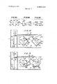
- FIG. 9 shows the relationship between axial directions in the case of two gyroscopes used, wherein FIG.
- FIG. 9(3) and FIG. 9(C) show respective modes diagrammatically.
- FIG. 10 and FIG. 11 show means for synchronizing the axial movement of two gyroscopes in the case where two gyroscopes are used, wherein FIG. 10 shows one example thereof and FIG. 11 shows another example thereof.
- FIG. 12 shows an embodiment of the directional control for gyroscope supports making use of wires.
- FIG. 13 shows said embodiment when said control is released.
- FIG. 14 is a partial side ther embodiment.
- FIG. 1 to FIG. 6 show the first embodiment in accordance with the present invention, in which a gyroscope is braked mechanically to a stop.
- Gyroscopic holder 1 comprises mounting base 2 for camera 13, handles 7 and 10 formed on the respective ends of mounting base 2, and casing 11 for the gyroscope beneath mounting base 2.
- fitting 9 for attaching flexible shaft 15, which is connectable to release button 14 for the camera 13.
- operation lever 19 (FIG. 6) is pivoted on shaft 20 and biased by 9.
- third projection 19c for entherein.
- movable gimbals 25b pivoted on shafts 26b and 27b relative to said fixed member 21b has spring 36b, connected between spring hanger portion 34b formed on the external perimeter of shaft 27b and spring hanger portion 35b of fixed support member 21b andis biased in a certain direction relative to fixed member 2Ib.
- a motor 23b is fixed to movable support 25b and a gyroscope 22b is fixed to its rotary shaft 24b.
- the directions of the rotary shafts of both gyroscopes 22a and 22b are controlled by said springs 36a and 36b, respectively.
- transmission lever 39 passing through opening 41 communicating between casing ll-and handle 7 is pivoted on shaft38 in casing 11, and the other end thereof is engageable with first projection 19a of said operation lever 19 in handle 7.
- -Operating rod 37 engageable with transmission lever 39 is slidably supported parallel to upper walllla'of the casing and is biased by spring 42 to engage transmission lever 39.
- Operating member 33 (FIG. 4) having arms 33a and 33b at right angles to each other is fixed to operating shaft 37.
- Brake shaft 30b (FIG. passing through shaft 27b of movable support25b has on its internal end a brakeshoe 29b slidably engageable with gyroscope 22b as shown in FIG. 5,.and said brake shaft 30b is urged outwardly'by spring 31b, in a direction to disengage brake shoe 29b from gyroscope 22b.
- the external end of said brake is in'contact with one arm 33b of operating member 33, to press brake shaft 30b inwardly by means of spring 32b having a spring force stronger than that of said spring 31b, and brake shoe 29b is pressed onto gyroscope 22b against the force of spring 31b.
- photographing is performed in the following sequencez
- Onto mounting base 2 of holder 1 camera 13 is fixed by screw 6, and to release button 14 and fitting 9 both ends of flexible shaft 15 accommodating release wire 43 are screwed respectively.
- Holding handles 7 and 10 are screwed respectively.
- I camera 13 is directed toward the object to be photo-.
- third projection 19c presses release wire 43 to release the shutter of camera 13.
- the optical axis of the camera on holder 1 is securely directed in the desired direction and there is no fear of spoiling the picture by reason of undesirable movements of the camera.
- first projection 19a of operation lever 19 is eliminated including. first projection 19a of operation lever 19, transmission lever 39, rotary shaft 38, operating shaft 37, operating member 33, springs 32a and 32b, brake shafts 30a and 30b, springs 31a and 31b, and .brake shoes 29a and 29b for braking gyroscopes 22a and 22b mechanically instead the braking of gyroscopes 22a and 22b is electrically effected.
- FIG. 7 and FIG. 8 the parts which are the same as those in the first embodiment are identified by the same reference characters as those in said first embodiment, and only the distinctions between said embodiments will be described in detail.
- Operation lever 19 has operating projection l9a and release projection l9c, and switch 44' operated by op erating projection l9a is composed of movable contact piece 44'a engageable with operating projection l9a, fixed contact piece 44b from which said movable contact piece 44'a has a tendency to open,
- movable contact piece 44'a and contact piece 44'a are connected in series to electric power sources 16 and 16' and motors 23a and 23b, and when contact piece 44'a comes into contact with contact piece 44b the motor driving circuit is closed. And, movable contact piece 44a and contact piece 44c are connected in series to respective shunts of r'notors 23a and 23b, and when contact piece 44'a comes into contact with contact piece 44'a the braking circuits of both motors 23a and 23b are closed.
- the motor driving circuit is first opened and then the motor braking circuit is closed, accordingly, the rotations of gyroscopes 22a and 22b are braked and shafts 24a and 24b of said gyroscopes if they have deviated in the course of their operation, are restored by springs 36a and 36b.
- gyroscope As regards the stability of holder 1 effected by a gyroscope it is preferable to use two or more gyroscopes with their axes at right angles to each other, however, for this purpose it is not always required to construct the device as shown by the first and second embodiments in FIG. 9 (A) but it is also possible to arrange the gyroscopes as shown in FIGS. 9 (B) and 9 (C).
- both gyroscopes are operated and even though the direction of their axes changes during operation, it is preferable that the rotary shafts of both gyroscopes are always at right angles to each other.
- FIG. and FIG. 11 Embodiments employing this arrangement are shown in FIG. and FIG. 11.
- rotary shafts 27a and 27b joumaled in fixed support members 21a and'21b and carrying movable supports a and 25b are provided with pullies 45a and 45b respectively connected by belt 46.
- rotary shafts 27a, and 27b for movable support 25a and 25b carry gears 4Sb and 4Sb of the same pattern, connected by intermediate gear 46'.
- Gyroscopes 22a and 22b can thus be prevented from changing position until the shutter is released.
- FIG. 14 This embodiment is shown in FIG. 14, wherein there is arranged retaining pin 51b which is slidably fitted in shaft hole 52b of fixed support member 21b and which is also biased by spring 53b so as to loosely fit in interb of movable support 25b release lever 54b interlocking with said retaining pin 51b is supported byshaft 55b so as to be in contact with fixed piece 56b to interlock therewith.
- Actuation piece 56b is interlocked with operation lever 19 and, by means of release lever 54b, retracts retaining pin 51b from movable support 25b, against spring 53b, immediately before the shutter is released by operation lever 19, and thereby locking is released.
- a gyroscope holder for a camera comprising:
- a mounting base for a camera and means for detachably fixing a camera thereon;
- said means for releasing the shutter of the camera fixed to the mounting base is an operation member'biased to a rest position by spring means, provided with an operation button, and movable to a position in which the shutter is released after said means for operating the gyroscope is activated,
- first switching means connected in series to said electric power source and motor
Landscapes
- Physics & Mathematics (AREA)
- Engineering & Computer Science (AREA)
- General Engineering & Computer Science (AREA)
- General Physics & Mathematics (AREA)
- Mechanical Engineering (AREA)
- Chemical & Material Sciences (AREA)
- Chemical Kinetics & Catalysis (AREA)
- Electrochemistry (AREA)
- General Chemical & Material Sciences (AREA)
- Optics & Photonics (AREA)
- Accessories Of Cameras (AREA)
Abstract
A holder for a camera to ensure a photograph unaffected by undesirable movement of a hand-held camera comprises a casing accommodating therein one or more gyroscopes; means for detachably securing the camera to said casing a pair of handles, and push button means associated with one of handles said for actuating the camera after a switch for operating the gyroscope or gyroscopes is closed, whereby the camera fixed to the holder is restrained from undesirable movement by operation of the gyroscope or gyroscopes during the exposure period.
Description
United States Patent 91 Mito GYROSCOPIC HOLDER FOR CAMERA Dec. 31, 1974 3,424,523 1/1969 Branigan 95/12.5x
Primary Examiner.1ohn M. Horan [57] ABSTRACT 6 Claims, 16 Drawing Figures [76] Inventor: Kunimasa Mito, 527
. Minaminakamoru, Omiya-shi, Japan [22] Filed: Oct. 4, 1973 [21] Appl. No.: 403,613
[52] US. Cl. 354/293 '[51] Int. Cl. G03b 17/56 [58] Field of Search 95/125, 31 EL, 86; 354/293 [56] References Cited UNITED STATES PATENTS 1,586,070 5/1926 Cooke 95/125 1,863,573 6/1932 Lutz 1 1 95/125 1,880,960 10/1932 -Keale 95/125 19a 7h/F 230 l 240 I9 [I PATENT DEC3 1 I974 SHEET 3 OF 7.
PATENTEUUEBBI I974 3,858,228
' SHEET 7 OF 7 FIG. 14
Ila
GYROSCOPIC HOLDER FOR CAMERA BACKGROUND OF THE INVENTION The present invention relates to a gyroscopic holder for a camerafor preventing undesirable movement of a hand-held camera during the exposure period.
In general, using a photographic camera exposure is performed while the camera is held in the hand, and the same is true in the case of a small-sized motion picture camera. Therefore, such cameras are subject to undesirable movement cause by hand movements, and in the case of a still camera it is difficult to obtain a good picture when the shutter speed is slow, and in the case of a motion picture camera the photographed object appears unstable. For such reasons, a tripod or the like is used to hold the camera, but a tripod is somewhat cumbersome, resulting in a reduction of the advantage otherwise inuring to a small-sized photographic camera or a small-sized motion picture camera.
in the course of its operation is aided to return to said position by brakingof the gyroscope simultaneously with the termination of the exposure period.
Still another object of the present invention is to provide a gyroscopic holder for a camera which stabilizes the optical axis of a camera in a certain direction by combining a plurality of gyroscopes so that the rotary axes thereof may be disposed at angles differing from one another as much as 90.
Other objects of the present invention will be apparent from the detailed description of the several embodiments.
SUMMARY OF THE INVENTION In order to attain the above-mentioned objects, the present invention relates toa gyroscopic holder for a camera, which comprises a casing accommodating therein one or more gyroscopes, means for operating the gyroscope or gyroscopes, means for detachably se-,
curing the camera to the holder, a pair of handles, and means associated with one of said handles to actuate the camera after the means for operating the gyroscope is'actuated.
Said means for operating the gyroscope can be a power source and switch means for energizing a motor for driving the gyroscope. It is also possible to incorporate means to brake the gyroscope when said switch means is operated to de-energize the motor.
The means for actuating the camera can be a push button associated with one of the handles so as to facilitate actuation the camera while holding the gyroscopic holder. Said push button operates the switch means to energize the motor in a first step operation, and actuates the camera'in a second step operation, and by releasing the push button a circuit for braking said motor 2 is constituted. Accordingly, the gyroscope always is operated during the exposure period.
Associated with each said gyroscope there is provided a spring for biasing its rotary axis to a certain direction relative to the casing so as to direct the axis of the gyroscope to the most effective direction to prevent the optical axis of the camera from deflecting, and the axial direction of the gyroscope, if deviated from said direction due to operation of the gyroscope, can be restored when the gyroscope is braked to a stop.
BRIEF DESCRIPTION OF THE DRAWINGS FIG. 1 is a top plan view of one embodiment in accor- I dance with the present invention.
FIG. 2 is a front elevation, partly in vertical section, of said embodiment on the mounting base of which a camera is attached.
FIG. 3 is a side elevation of said embodiment.
' FIG. 4 is a fragmentary front view of said embodiment, partly in vertical section.
FIG. 5 is a fragmentary side view of said gyroscope in vertical section. I
FIG.'6 is a side view bodiment.
FIG. 7 is a side view in vertical section of another embodiment in accordance with the present invention.
FIG. 8' is a circuit diagram of the means for driving and controlling the gyroscope of said embodiment.
FIG. 9 shows the relationship between axial directions in the case of two gyroscopes used, wherein FIG.
in vertical section of said em- 9(A), FIG. 9(3) and FIG. 9(C) show respective modes diagrammatically.
FIG. 10 and FIG. 11 show means for synchronizing the axial movement of two gyroscopes in the case where two gyroscopes are used, wherein FIG. 10 shows one example thereof and FIG. 11 shows another example thereof.
FIG. 12 shows an embodiment of the directional control for gyroscope supports making use of wires. FIG. 13 shows said embodiment when said control is released.
' view in vertical section a fur- FIG. 14 is a partial side ther embodiment.
DETAILED DESCRIPTION OF THE INVENTION:
FIG. 1 to FIG. 6 show the first embodiment in accordance with the present invention, in which a gyroscope is braked mechanically to a stop.
. To mounting base 2 an elastic sheet 3 is adhered, on which the bottom of camera 13 rests and in the center of said base 2 there is provided a hole 4 through which a screw 6 passes, to be screwed into a threaded hole provided on the bottom of the camera Knob 5 for rotating said screw 6 has a portion projecting at the rear, on the under side of mounting base 2.
As shown in the front view of FIG. 2, at the front of left handle 7 there is provided fitting 9 for attaching flexible shaft 15, which is connectable to release button 14 for the camera 13. Inside of handle 7 an operation lever 19 (FIG. 6) is pivoted on shaft 20 and biased by 9. As shown in FIG. 6, on the front edge of operation lever 19 there are provided third projection 19c for entherein.
To top plate 11a of casing 11 (FIG. 4) on the lower, side of mounting base 2, two support members'Zla and 21b are fixed. Said fixed support member 21a and 21b are of the same pattern and only one of them,-member 21b, will be described. As shown in FIG. 5, movable gimbals 25b pivoted on shafts 26b and 27b relative to said fixed member 21b has spring 36b, connected between spring hanger portion 34b formed on the external perimeter of shaft 27b and spring hanger portion 35b of fixed support member 21b andis biased in a certain direction relative to fixed member 2Ib.
A motor 23b is fixed to movable support 25b and a gyroscope 22b is fixed to its rotary shaft 24b.
In order that the rotary shafts of the two gyroscopes 2 2a and 22b may be at right angles to each other and that the plane formed by both rotary shafts may be at right angles to the optical axis of the camera attached to mounting base 2, the directions of the rotary shafts of both gyroscopes 22a and 22b are controlled by said springs 36a and 36b, respectively.
One end of transmission lever 39 passing through opening 41 communicating between casing ll-and handle 7 is pivoted on shaft38 in casing 11, and the other end thereof is engageable with first projection 19a of said operation lever 19 in handle 7.-Operating rod 37 engageable with transmission lever 39 is slidably supported parallel to upper walllla'of the casing and is biased by spring 42 to engage transmission lever 39.
' Operating member 33 (FIG. 4) having arms 33a and 33b at right angles to each other is fixed to operating shaft 37. Brake shaft 30b (FIG. passing through shaft 27b of movable support25b has on its internal end a brakeshoe 29b slidably engageable with gyroscope 22b as shown in FIG. 5,.and said brake shaft 30b is urged outwardly'by spring 31b, in a direction to disengage brake shoe 29b from gyroscope 22b. The external end of said brake is in'contact with one arm 33b of operating member 33, to press brake shaft 30b inwardly by means of spring 32b having a spring force stronger than that of said spring 31b, and brake shoe 29b is pressed onto gyroscope 22b against the force of spring 31b.
As shown in FIG. 6, facing second projection 19b of operation lever 19 there is providednormally open switch 44 between motors 23a and 23b and electric power sources 16 and 16'.
In the case of the embodiment as described'above, photographing is performed in the following sequencez Onto mounting base 2 of holder 1 camera 13 is fixed by screw 6, and to release button 14 and fitting 9 both ends of flexible shaft 15 accommodating release wire 43 are screwed respectively. Holding handles 7 and 10,
I camera 13 is directed toward the object to be photo-.
graphed and brought into focus. Then upon pushing operation button 8 against spring 40, first projection 19a engages with transmission lever 39 to turn it on shaft 38 as a center, and operating rod 37 engaging with transmission lever 39, slides to the right side in FIG. 6 against spring 42 and both operating members 33a and 33b are moved to the right against springs 32a and 32b, therefore, brake shafts 30a and 30b are moved 4 outwardly in FIG. 5, respectively by springs 31a and 31b, to brake shoes 29a and 29b respectively from gyroscopes 22a and 22b'and thus release the 1 Then, in the second step second projection 19b of operation lever 19 closes switch 44 to drive motors 23a and 23b to rotate gyroscopes 22a and 22b, respectively, and stabilize the holder 1.
Further, in the third step third projection 19c presses release wire 43 to release the shutter of camera 13.
Therefore,.when the film is exposed the optical axis of the camera on holder 1 is securely directed in the desired direction and there is no fear of spoiling the picture by reason of undesirable movements of the camera.
As operation button 8 is released, after switch 44 is opened the brake shoes 29a and 29b are brought into contact with gyroscopes 22a and 22b by means of .by springs 36a and 36b respectively to return to their original state.
In the second embodiment of the present invention shown various elements of FIG. 7 and FIG. 8, in the first embodiment are eliminated including. first projection 19a of operation lever 19, transmission lever 39, rotary shaft 38, operating shaft 37, operating member 33, springs 32a and 32b, brake shafts 30a and 30b, springs 31a and 31b, and .brake shoes 29a and 29b for braking gyroscopes 22a and 22b mechanically instead the braking of gyroscopes 22a and 22b is electrically effected. In said FIG. 7 and FIG. 8 the parts which are the same as those in the first embodiment are identified by the same reference characters as those in said first embodiment, and only the distinctions between said embodiments will be described in detail.
As shown in FIG. 8, movable contact piece 44'a and contact piece 44'a are connected in series to electric power sources 16 and 16' and motors 23a and 23b, and when contact piece 44'a comes into contact with contact piece 44b the motor driving circuit is closed. And, movable contact piece 44a and contact piece 44c are connected in series to respective shunts of r'notors 23a and 23b, and when contact piece 44'a comes into contact with contact piece 44'a the braking circuits of both motors 23a and 23b are closed.
That is to say,- when operation button 8 is not pushed the motor braking circuit is closed by spring 40, and gyroscopes 22a and 22b are braked. In the first step in which operation button 8 ispressed against spring 40, first of all the braking circuit is opened and in the sechanger portion 19'd locking hole ond step in which operation button 8 is further pressed, the motor driving circuit is closed and gyroscopes 22a and 22b are caused to rotate. In the third step in which operation button 8 is pressed further release projection l9'c comes into contact with release wire 43 to release the shutter.
As operation button 8 is released, the motor driving circuit is first opened and then the motor braking circuit is closed, accordingly, the rotations of gyroscopes 22a and 22b are braked and shafts 24a and 24b of said gyroscopes if they have deviated in the course of their operation, are restored by springs 36a and 36b.
As regards the stability of holder 1 effected by a gyroscope it is preferable to use two or more gyroscopes with their axes at right angles to each other, however, for this purpose it is not always required to construct the device as shown by the first and second embodiments in FIG. 9 (A) but it is also possible to arrange the gyroscopes as shown in FIGS. 9 (B) and 9 (C).
In these cases, both gyroscopes are operated and even though the direction of their axes changes during operation, it is preferable that the rotary shafts of both gyroscopes are always at right angles to each other.
Embodiments employing this arrangement are shown in FIG. and FIG. 11. In the embodiment shown in FIG. 10, rotary shafts 27a and 27b joumaled in fixed support members 21a and'21b and carrying movable supports a and 25b, are provided with pullies 45a and 45b respectively connected by belt 46. In the embodiment shown in FIG. 11, rotary shafts 27a, and 27b for movable support 25a and 25b carry gears 4Sb and 4Sb of the same pattern, connected by intermediate gear 46'.
In the above-mentioned first and second embodiments, when gyroscopes 22a and 22b are stopped the deviation brought about in the course of their operation is restored by springs 36a and 36b; however, it can similarly 'be restored by wires connected to operation lever 19. Such arrangements are shown in FIG. 12 and FIG. 13, wherein, to hanger portions 34a and 34b of rotary shafts 27a and 27b, one end of each of wires 47a and 47b, respectively, other ends of said wires 47a and 47b being fastened to of operation lever 19 through swivel pullies 48 and 49 respectively. When operation lever 19 is released wires 47a and 47b are tensioned by spring 40 to regulate the directions of rotary shafts 27a is fastened respectively and the and 27b, and when operation button 8 is pushed wires I 47a and 47b are slackened to permit themovement of rotary shafts 27a and 27b. effected by their operation.
Further, when said wires 47a and 47b are tensioned and the rotary shafts of movable supports 25a and 25b take a certain direction relative to fixed support'members 21a and 21b, there is provided a means for locking the shafts 26a and 27a and 26b and 27b. Said locking is designed to be released after operation lever 19 is op-,
erated to actuate gyroscopes 22a and 22b, and just before the shutter is released. Gyroscopes 22a and 22b can thus be prevented from changing position until the shutter is released.
This embodiment is shown in FIG. 14, wherein there is arranged retaining pin 51b which is slidably fitted in shaft hole 52b of fixed support member 21b and which is also biased by spring 53b so as to loosely fit in interb of movable support 25b release lever 54b interlocking with said retaining pin 51b is supported byshaft 55b so as to be in contact with fixed piece 56b to interlock therewith.
Although the invention has been described in its preferred form with a certain degree of particularity, it is understood that the present disclosure of the preferred form can be changed in the details of construction and that variations in the arrangement of parts may be resorted to without departing from the spirit and the scope of the invention as hereinafter claimed.
What is claimed is:
1. A gyroscope holder for a camera comprising:
a mounting base for a camera and means for detachably fixing a camera thereon;
a casing containing a gyroscope mounted on pivots around which its rotary shaft can move angularly;
means for-operating said gyroscope;
handles provided on both sides of said mounting base; and
means associated with one of said handles for first activating said means for operating said gyroscope and then releasing the shutter of a camera fixed to said mounting base, wherein said means for releasing the shutter of the camera fixed to the mounting base is an operation member'biased to a rest position by spring means, provided with an operation button, and movable to a position in which the shutter is released after said means for operating the gyroscope is activated,
and further comprising means for braking the rotation of the gyroscope when said operation member is situated in the rest position.
2. A gyroscopic holder for a camera as claimed in claim 1, wherein said casing is provided with a plurality of gyroscopes therein, said braking means serving to brake all gyroscopes at the same time when said operation member is situated in the rest position.
3. A gyroscopic holder for a camera as claimed in claim 2, further comprising: I
means for biasing the axial direction of said gyroscopes so that their respective axes are at right angles to one another when said gyroscopes are braked to a stop.
4. A gyroscopic holder for a camera as claimed in claim 3, further comprising:
means for holding therespective axes of said gyroscopes at angles of to each other during angular movements of the respective axes of said gyroscopes, when a plurality of gyroscopes are operated.
5. A gyroscopic holder for a camera as claimed in claim 1, further comprising:
a motor for driving said gyroscope;
an electric power source for energizing said motor;
first switching means connected in series to said electric power source and motor;
a motor braking circuit for short-circuiting across both terminals of said motors; and
second switching means connected in series to said motor braking circuit.
6. A gyroscopic holder for a camera as claimed in claim 5, wherein movement of said operating member to the first rest position closes said second switching means, movement of said member to a second position opens said second switching means, movement of said member to a third position holds said second switching means open and closes the first switching means, and movement of said member to a fourth operating posi-
Claims (6)
1. A gyroscope holder for a camera comprising: a mounting base for a camera and means for detachably fixing a camera thereon; a casing containing a gyroscope mounted on pivots around which its rotary shaft can move angularly; means for operating said gyroscope; handles provided on both sides of said mounting base; and means assocIated with one of said handles for first activating said means for operating said gyroscope and then releasing the shutter of a camera fixed to said mounting base, wherein said means for releasing the shutter of the camera fixed to the mounting base is an operation member biased to a rest position by spring means, provided with an operation button, and movable to a position in which the shutter is released after said means for operating the gyroscope is activated, and further comprising means for braking the rotation of the gyroscope when said operation member is situated in the rest position.
2. A gyroscopic holder for a camera as claimed in claim 1, wherein said casing is provided with a plurality of gyroscopes therein, said braking means serving to brake all gyroscopes at the same time when said operation member is situated in the rest position.
3. A gyroscopic holder for a camera as claimed in claim 2, further comprising: means for biasing the axial direction of said gyroscopes so that their respective axes are at right angles to one another when said gyroscopes are braked to a stop.
4. A gyroscopic holder for a camera as claimed in claim 3, further comprising: means for holding the respective axes of said gyroscopes at angles of 90* to each other during angular movements of the respective axes of said gyroscopes, when a plurality of gyroscopes are operated.
5. A gyroscopic holder for a camera as claimed in claim 1, further comprising: a motor for driving said gyroscope; an electric power source for energizing said motor; first switching means connected in series to said electric power source and motor; a motor braking circuit for short-circuiting across both terminals of said motors; and second switching means connected in series to said motor braking circuit.
6. A gyroscopic holder for a camera as claimed in claim 5, wherein movement of said operating member to the first rest position closes said second switching means, movement of said member to a second position opens said second switching means, movement of said member to a third position holds said second switching means open and closes the first switching means, and movement of said member to a fourth operating position holds said second switching means open and the first switching means closed while releasing the camera shutter.
Priority Applications (1)
| Application Number | Priority Date | Filing Date | Title |
|---|---|---|---|
| US00403613A US3858228A (en) | 1973-10-04 | 1973-10-04 | Gyroscopic holder for camera |
Applications Claiming Priority (1)
| Application Number | Priority Date | Filing Date | Title |
|---|---|---|---|
| US00403613A US3858228A (en) | 1973-10-04 | 1973-10-04 | Gyroscopic holder for camera |
Publications (1)
| Publication Number | Publication Date |
|---|---|
| US3858228A true US3858228A (en) | 1974-12-31 |
Family
ID=23596410
Family Applications (1)
| Application Number | Title | Priority Date | Filing Date |
|---|---|---|---|
| US00403613A Expired - Lifetime US3858228A (en) | 1973-10-04 | 1973-10-04 | Gyroscopic holder for camera |
Country Status (1)
| Country | Link |
|---|---|
| US (1) | US3858228A (en) |
Cited By (7)
| Publication number | Priority date | Publication date | Assignee | Title |
|---|---|---|---|---|
| US4007470A (en) * | 1974-12-19 | 1977-02-08 | Polaroid Corporation | Battery operated camera having a handle thereon formed in part by an external battery |
| US4218122A (en) * | 1979-07-30 | 1980-08-19 | Drafahl Jack W Jr | Light-handle |
| US4752792A (en) * | 1986-11-26 | 1988-06-21 | Keith Carl D | Camera support and accessory storage apparatus storagrip |
| US4774589A (en) * | 1986-03-03 | 1988-09-27 | Rowland David A | Optical system image stabilizer employing electromechanical torque sensors |
| US5963749A (en) * | 1998-02-09 | 1999-10-05 | Nicholson; Lynn | Self-leveling invertible camera stabilizer |
| US20070076115A1 (en) * | 2005-09-12 | 2007-04-05 | Junji Hirooka | Image pickup apparatus |
| CN102353365A (en) * | 2011-09-19 | 2012-02-15 | 天津全华时代航天科技发展有限公司 | Gyroscope holder of unmanned aerial vehicle |
Citations (4)
| Publication number | Priority date | Publication date | Assignee | Title |
|---|---|---|---|---|
| US1586070A (en) * | 1921-08-03 | 1926-05-25 | Aero Survey Corp | Method of taking photographs and camera mounting for use in connection therewith |
| US1863573A (en) * | 1931-07-03 | 1932-06-21 | Fairchild Aerial Camera Corp | Camera mechanism |
| US1880960A (en) * | 1929-06-03 | 1932-10-04 | Jr Charles F Keale | Aerial camera |
| US3424523A (en) * | 1965-10-24 | 1969-01-28 | Bell & Howell Co | Motion picture camera having a rotating gyroscopically stabilized lens and a variable erection rate means |
-
1973
- 1973-10-04 US US00403613A patent/US3858228A/en not_active Expired - Lifetime
Patent Citations (4)
| Publication number | Priority date | Publication date | Assignee | Title |
|---|---|---|---|---|
| US1586070A (en) * | 1921-08-03 | 1926-05-25 | Aero Survey Corp | Method of taking photographs and camera mounting for use in connection therewith |
| US1880960A (en) * | 1929-06-03 | 1932-10-04 | Jr Charles F Keale | Aerial camera |
| US1863573A (en) * | 1931-07-03 | 1932-06-21 | Fairchild Aerial Camera Corp | Camera mechanism |
| US3424523A (en) * | 1965-10-24 | 1969-01-28 | Bell & Howell Co | Motion picture camera having a rotating gyroscopically stabilized lens and a variable erection rate means |
Cited By (8)
| Publication number | Priority date | Publication date | Assignee | Title |
|---|---|---|---|---|
| US4007470A (en) * | 1974-12-19 | 1977-02-08 | Polaroid Corporation | Battery operated camera having a handle thereon formed in part by an external battery |
| US4218122A (en) * | 1979-07-30 | 1980-08-19 | Drafahl Jack W Jr | Light-handle |
| US4774589A (en) * | 1986-03-03 | 1988-09-27 | Rowland David A | Optical system image stabilizer employing electromechanical torque sensors |
| US4752792A (en) * | 1986-11-26 | 1988-06-21 | Keith Carl D | Camera support and accessory storage apparatus storagrip |
| US5963749A (en) * | 1998-02-09 | 1999-10-05 | Nicholson; Lynn | Self-leveling invertible camera stabilizer |
| US20070076115A1 (en) * | 2005-09-12 | 2007-04-05 | Junji Hirooka | Image pickup apparatus |
| CN102353365A (en) * | 2011-09-19 | 2012-02-15 | 天津全华时代航天科技发展有限公司 | Gyroscope holder of unmanned aerial vehicle |
| CN102353365B (en) * | 2011-09-19 | 2013-06-05 | 天津全华时代航天科技发展有限公司 | Gyroscope holder of unmanned aerial vehicle |
Similar Documents
| Publication | Publication Date | Title |
|---|---|---|
| US5708890A (en) | Tripod | |
| US4736217A (en) | Camera platform for tripod mounting | |
| US3858228A (en) | Gyroscopic holder for camera | |
| JPS6336328Y2 (en) | ||
| JPH03130756A (en) | Camera | |
| WO2019024119A1 (en) | Remote controller and photographing device | |
| US6166765A (en) | Electronic imaging apparatus selecting an operating mode responsive to the condition of a lens barrier assembly | |
| US4314750A (en) | Tactile indication and control system | |
| US3947860A (en) | Remote focusing device for cameras | |
| CN108541295B (en) | Remote controller | |
| US3474715A (en) | Device for elevating and lowering the reflecting mirror of single lens reflex cameras | |
| US5652935A (en) | Camera controlling tripod locking | |
| JP2773230B2 (en) | TV camera lens device | |
| US3792649A (en) | Automatic return mechanism for an exposure trim assembly | |
| JPH07191388A (en) | Winding device of film containing camera | |
| JPS5948743A (en) | Parallax correcting device of camera | |
| JPS62246019A (en) | Camera system | |
| JPH01258562A (en) | Camera installing device | |
| JPH03289640A (en) | Tripod for film incorporated type camera | |
| KR0126616Y1 (en) | Rotation apparatus of video camera for closed-circuit television in order to transfer real-image | |
| JP3005685U (en) | Aiming frame switching device in the finder box | |
| US4162838A (en) | Camera viewfinder | |
| JPS634168Y2 (en) | ||
| RU2142154C1 (en) | Photographic camera fitted with five lenses with mobile mask for single or quadruple pictures | |
| JPS58216227A (en) | Device for switching exposure mode of interchangeable lens |