US3876149A - Method of forming a torch tip and torch tips - Google Patents
Method of forming a torch tip and torch tips Download PDFInfo
- Publication number
- US3876149A US3876149A US354535A US35453573A US3876149A US 3876149 A US3876149 A US 3876149A US 354535 A US354535 A US 354535A US 35453573 A US35453573 A US 35453573A US 3876149 A US3876149 A US 3876149A
- Authority
- US
- United States
- Prior art keywords
- openings
- chamber
- gas
- block
- row
- Prior art date
- Legal status (The legal status is an assumption and is not a legal conclusion. Google has not performed a legal analysis and makes no representation as to the accuracy of the status listed.)
- Expired - Lifetime
Links
Images



Classifications
-
- F—MECHANICAL ENGINEERING; LIGHTING; HEATING; WEAPONS; BLASTING
- F23—COMBUSTION APPARATUS; COMBUSTION PROCESSES
- F23D—BURNERS
- F23D14/00—Burners for combustion of a gas, e.g. of a gas stored under pressure as a liquid
- F23D14/46—Details
- F23D14/48—Nozzles
- F23D14/52—Nozzles for torches; for blow-pipes
-
- B—PERFORMING OPERATIONS; TRANSPORTING
- B23—MACHINE TOOLS; METAL-WORKING NOT OTHERWISE PROVIDED FOR
- B23P—METAL-WORKING NOT OTHERWISE PROVIDED FOR; COMBINED OPERATIONS; UNIVERSAL MACHINE TOOLS
- B23P15/00—Making specific metal objects by operations not covered by a single other subclass or a group in this subclass
-
- B—PERFORMING OPERATIONS; TRANSPORTING
- B23—MACHINE TOOLS; METAL-WORKING NOT OTHERWISE PROVIDED FOR
- B23P—METAL-WORKING NOT OTHERWISE PROVIDED FOR; COMBINED OPERATIONS; UNIVERSAL MACHINE TOOLS
- B23P15/00—Making specific metal objects by operations not covered by a single other subclass or a group in this subclass
- B23P15/16—Making specific metal objects by operations not covered by a single other subclass or a group in this subclass plates with holes of very small diameter, e.g. for spinning or burner nozzles
-
- C—CHEMISTRY; METALLURGY
- C03—GLASS; MINERAL OR SLAG WOOL
- C03B—MANUFACTURE, SHAPING, OR SUPPLEMENTARY PROCESSES
- C03B23/00—Re-forming shaped glass
- C03B23/04—Re-forming tubes or rods
- C03B23/043—Heating devices specially adapted for re-forming tubes or rods in general, e.g. burners
-
- Y—GENERAL TAGGING OF NEW TECHNOLOGICAL DEVELOPMENTS; GENERAL TAGGING OF CROSS-SECTIONAL TECHNOLOGIES SPANNING OVER SEVERAL SECTIONS OF THE IPC; TECHNICAL SUBJECTS COVERED BY FORMER USPC CROSS-REFERENCE ART COLLECTIONS [XRACs] AND DIGESTS
- Y10—TECHNICAL SUBJECTS COVERED BY FORMER USPC
- Y10T—TECHNICAL SUBJECTS COVERED BY FORMER US CLASSIFICATION
- Y10T29/00—Metal working
- Y10T29/49—Method of mechanical manufacture
- Y10T29/49428—Gas and water specific plumbing component making
- Y10T29/49432—Nozzle making
-
- Y—GENERAL TAGGING OF NEW TECHNOLOGICAL DEVELOPMENTS; GENERAL TAGGING OF CROSS-SECTIONAL TECHNOLOGIES SPANNING OVER SEVERAL SECTIONS OF THE IPC; TECHNICAL SUBJECTS COVERED BY FORMER USPC CROSS-REFERENCE ART COLLECTIONS [XRACs] AND DIGESTS
- Y10—TECHNICAL SUBJECTS COVERED BY FORMER USPC
- Y10T—TECHNICAL SUBJECTS COVERED BY FORMER US CLASSIFICATION
- Y10T29/00—Metal working
- Y10T29/49—Method of mechanical manufacture
- Y10T29/49995—Shaping one-piece blank by removing material
- Y10T29/49996—Successive distinct removal operations
Definitions
- ABSTRACT A process is provided for forming a torch tip having a first chamber and a second chamber from a solid metal block having a first side and an opposing second side.
- a first row of spaced openings which are separated from each other by metal is drilled in the first side of the block partially through the block.
- An overlapping opening is then drilled from the second side of the block between each two adjacent openings of the first row.
- Each overlapping opening has a diameter greater than the space between its two adjacent openings of the first row so that it intersects both of its two adjacent openings.
- Each overlapping opening is drilled to extend partially through the block to remove metal between its two adjacent openings of the first row and thereby form a first chamber in the block.
- the outer ends of the drilled openings of the first row and each overlapping opening is sealed to form an enclosed first chamber.
- a sealed second chamber spaced from the first chamber by a web is formed in an identical manner to the first chamber.
- First and second gas inlets are provided for the first and second chambers, respectively as well as first and second gas outlet means.
- Torch tips of various types and configurations have been known and used to perform different functions, and although these torch tips have served the purpose they have not proved entirely satisfactory under all conditions of service.
- many of the prior art torch tips have required the use of a large number of parts to form the necessary gas and cooling passages.
- the use of a plurality of parts has resulted in high cost to manufacture and repair.
- Torch tips are frequently formed with an upper first chamber and a lower second chamber which receive different gases that are mixed outside of the tip to produce combustion.
- these first and second chambers have been provided by securing cast and other parts together such as by soldering or welding the parts.
- Torch tips have also been produced by drilling holes in solid blocks of metal, but in the past it has been difficult to form long torch tips by this method because a drilled hole cannot be accurately positioned in a desired area over a substantial length.
- these holes have been separated from each other by metal and extra care had to be used in locating gas outlet passages to insure that they would communicate with the interior drilled holes.
- Torch tips are often used to work and shape glass or quartz articles such as quartz tubes. These tubes require large amounts of heat to bring them to a desired working temperature and are often fire polished on the inside of the tube.
- torch tips designed for application with quartz and glass tubes have been subject to self-destruction because of the high heat generated by the torch tips during their operation.
- the present invention provides an improved method for forming a torch tip having a first chamber and a second chamber from a solid block of metal having a first side and an opposing second side.
- the method of the present invention comprises drilling from the first side of the block partially through the block a first row of spaced openings which are separated from each other by metal; drilling an overlapping opening from the second side of the block between each two adjacent openings of the first row, with each overlapping opening intersecting both of its two adjacent openings and extending partially through the block to remove metal between its two adjacent openings of the first row and thereby form a first chamber within the block; sealing the outer ends of the drilled openings of the first row and each overlapping opening to form an enclosed first chamber; drilling from one of the first and second sides partially through the block a second row of spaced openings which are separated from each other by metal, with the first and second rows of openings being spaced from each other to define a web between them; drilling an overlapping opening
- the method of this invention enables torch tips to be produced from solid metal blocks by easily performed drilling operations.
- the chambers of the torch tip can be produced in any desired length as it is necessary to increase only the length of the block and number of drilled openings in the sides of the block to produce a longer torch tip and it is unnecessary to increase the length of the drilled openings.
- a variety of torch tip shapes can be produced by the present method including torch tips having rectangular, cylindrical and annular shapes.
- the second row of openings is drilled from the first side ofthe block and each overlapping opening for the second row is drilled from the second side of the block. It is also preferred to form a plurality of first gas outlet passages for the first chamber and a plurality of second gas outlet passages for the second chamber, with each second gas outlet passage being concentrically positioned within a first gas outlet passage.
- the first and second rows of openings and the overlapping openings for these rows are drilled parallel to each other.
- the block is cylindrical and the openings for the first and second rows and the overlapping openings for these rows are drilled to extend radially inwardly toward and beyond the center of the block.
- an improved torch tip which comprises a first gas chamber and a second gas chamber which supply gases for producing a flame, a first manifold extending into the first chamber and having a series of axially spaced openings for distributing gas to the first chamber, and a second manifold extending into the second chamber and having a series of axially spaced openings for distributing gas to the second chamber.
- means are provided for removably plugging any of the openings of the first and second manifolds to block the flow of gas through the plugged openings and increase the flow of gas through remaining un plugged openings.
- Theaxially spaced openings of the manifold preferably are threaded and the means for removably pulgging any of the openings of the first and second manifolds comprises threaded plugs which en-' gage the threaded openings.
- a torch tip which comprises a body. outlet means for supplying flame producing gases, and a series of'gas jet holes in the body and about the outlet means for creating a sheet of confining gas about the flame produced by the torchi tip.
- this torch tip includes a firstplurality o fjet holes about a first side of the outlet means for producing a first gas sheet and a second plurality of jet, holes about a second side of the outlet means for producing a second gas sheet.
- the first and second plurality ofjet holes can converge toward each other as they emerge from the body or can diverge from each other. as they emerge from the body.
- the present invention also provides a torch comprising a solid cylindrical body having a cylindrical side wall and a planar end wall; a first axially extending gas supply passage having an inner end which terminates within the body; a second axially extending gas supply passage having an inner end which terminates within the body; a plurality of first gas outlet passages which communicate with the first gas supply passage and have their outer ends formed in the cylindrical side wall; a plurality of second gas outlet passages in the form of tubes which communicate with the second gas supply passage and have their outer ends formed in the cylindrical side wall adjacent the outer ends of the first gas outlet passages, with each one of the second gas outlet passages being concentrically positioned within one of the first gas outlet passages, and the axes ofthe first and second gas outlet passages forming an acute angle with the cylindrical side wall.
- the present invention also provides a torch tip comprising a solid body having a top wall. a bottom wall, a first side wall, an opposing second side wall. a back wall and a front wall which slopes downwardly from said top wall away from the back wall; a first chamber in the body; a second chamber in the body; a plurality of first gas outlet passages which communicate with the first chamber and have their outer ends formed in the front wall; a plurality of second gas outlet passages which communicate with the second chamber and have their outer'ends'terminate in the front wall.
- This torch tip can constitute one part of a torch having a first gas supply tube connected to the first chamber of the torch tip, a second gas supply tube connected to the second chamber of the torch tip. an end member having a first passage which 'receivesthe first gas supply tube and a second passage whichreceives the second gas supply tube. first and second inlet openings in the end member for distributing first and second gases to the first and second passages of the end member, and a handle about the first and second tubes and connecting the torch tip to the end member.
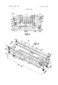
- FIG. 1 is a perspective view of a torch tip having a substantially rectangular shape and produced in accordance with the method teachings of this invention.
- FIG. 2 is a horizontal section taken along the line 2-2 of FIG. 1 and showing the first chamber of the torch tip of FIG. 1.
- FIG. 3 is a vertical sectional view taken along the line 3-3 of FIG. 2 and showing a lateral cross-section of the first and second chambers of the torch tip.
- FIG. 4 is a vertical sectional view taken along the line 4-4 of FIG. 2 and showing a longitudinal cross section of the first and second chambers of the torch tip.
- FIG. 5 is a sectional view of an alternate embodiment of a torch tip constructed in accordance with the teachings of the present invention and having manifolds for distributing incoming gases and a gas muffle for confining the flame emitted from the torch tip.
- FIG. 6 is a vertical sectional view taken along the line 6-6 of FIG. 5.
- FIG. 7 is a perspective view showing cooling means, a gas muffle, and manifolds of the torch tip of FIG. 5 with the outline of the torch tip in phantom line and with other parts of the torch tip removed for purposes of clarity.
- FIG. 8 is a perspective view of an embodiment of a cylindrical torch tip constructed in accordance with the present invention.
- FIG. 9 is a horizontal sectional view taken along the line 9'9 of FIG. 8 and showing a first chamber of the torch tip of FIG. 8.
- FIG. 10 is a horizontal sectional view taken along the line l0-10 of FIG. Sand shows a cooling water passage for the torch tip of FIG. 8'.
- FIG. 11 is a perspective view of an alternate embodiment of an annular torch tip constructed in accordance with the teachings of the present invention.
- FIG. l2 is a vertical sectional view taken along the line 12-12 of-FIG. 11.
- FIG. 13 is a vertical sectional view taken along the line 13-l3 of FIG. 11.
- FIG. 14 is a perspective view of an alternate embodiment of a torch tip which is particularly designed for polishing the inside surface of a quartz or glass tube.
- FIG.15 is a vertical sectional view taken along the line l5-l5 of FIG. 14.
- FIG. 16 is a vertical sectional view taken along the line l616 of FIG. 15.
- FIG. 17 is a vertical sectional view taken along the line 17-17 of FIG. 15.
- FIG. 18 is a side view of an alternate embodiment of a torch tip constructed in accordance with the method teachings of the present invention and which is especially useful for polishing the inside of a quartz or glass tube. 1
- FIG. 19 is a top-view of the torch vtip shown in FIG. 18.
- FIG. 20 is a vertical sectional view taken along the line 20-20 of FIG. 19.
- FIG. 21 is a vertical sectional view taken along the line 21-21 of FIG. 19.
- FIG. 22 is an end view showing the use of two tips on opposite sides of a glass or quartz tube, with each tip having an air muffle.
- Torch tip constructed from a solid metal block 11 in accordance with the method of the present invention.
- Torch tip is generally rectangular in shape and has a first longitudinally extending side 12, an opposing second longitudinally extending side 14, a top wall 16, a bottom wall 18, a first end wall and an opposing second end wall 22.
- a first row of spaced openings which are separated from each other by metal is drilled from the first side of block partially through the block.
- a first row of openings comprising four openings 24, 26, 28 and 30, are drilled from first side 12 of block 11. Openings 24, 26, 28 and 30, as best seen in FIG. 2, are parallel to each other and extend perpendicular to side 12 of block 11. The outer peripheries of openings 24, 26, 28 and 30, are separated from each other by metal areas 13. Openings 24,
- an overlapping opening is drilled from the second side of the block between each two adjacent openings of the first row.
- Each overlapping opening intersects both of its two adjacent openings of the first row and is drilled to extend partially through the block to remove metal between its two adjacent openings of the first row and thereby form a first chamber within the block.
- a first set of openings comprising three overlapping openings 34, 36 and 38 are drilled into block 11 from side 14 of the block. Opening 34 is drilled between adjacent openings 24 and 26 of the first row, opening 36 is drilled between adjacent openings 26 and 28, and opening 38 is drilled between adjacent openings 28 and 30. Openings 34, 36, and 38 are parallel to each other and to openings 24, 26, 28 and 30 of the first row. The outer peripheries of openings 34, 36 and 38 are separated from each other by metal areas 39.
- Openings 34, 36 and 38 extend from second side 14 partially through the block, and as best seen in FIG. 2 terminate in pointed inner ends inside block 11.
- the diameters of openings 34, 36 and 38 are greater than the space between their respective two adjacent openings of the first row.
- opening 34 intersects the outer sides of its adjacent openings 24 and 26
- opening 36 intersects the outer sides of its adjacent openings 26 and 28,
- opening 38 intersects the outer sides of its adjacent openings 28 and 30.
- Openings 34 and 36 and 38 are drilled deep enough into block 11 so that they extend between the inner ends 32 of openings 24, 26, 28 and 30 and side 12 of the block and remove a portion from each of the corresponding metal areas 13 between openings 24, 26, 28 and 30 of the first row. Removal ofa portion of each metal area 13 within block 11 enables each of the openings 24, 26, 28 and 30 to be in fluid communication with each other through the removed areas and re-. sults in the forming of a first chamber, generally 42.
- the outer ends of the drilled openings of the first row and of each overlapping opening are sealed to form an enclosed first chamber.
- the outer ends of drilled openings 24, 26, 28 and 30 and of overlapping openings 34, 36 and 38 are threaded.
- the openings can be threaded by any conventional means, such as by a tap.
- the threaded ends of openings 24, 26, 28 and 30 are sealed by threaded plugs 44 and the threaded ends of openings 34, 36 and 38 similarly are sealed by threaded plugs 46.
- first chamber 42 is sealed so that gas cannot escape from the ends of the drilled openings.
- the outer ends of the openings can be closed by other conventional means, such as, for example solder.
- Sealed chamber 42 is substantially rectangular in overall shape and is parallel to top wall 16. Openings 24, 26, 28 and 30 extend past the center of block 11 from side 12 and similarly openings 34, 36 and 38 extend past the center of the block from side 14 so that enclosed chamber 42 occupies a substantial portion of the interior of the block. Preferably, openings 34, 36 and 38 are the same length as openings 24, 26, 28 and 30 so that the drilling operation for forming chamber 42 can be easily performed with only one setting of drill length.
- a second row of spaced openings which are separated from each other by metal are drilled from one of the first and second sides of the block partially through the block.
- the second row of openings are spaced from the first row of openings to define a web between the first and second rows.
- a second row of openings comprising three openings 48, 50 and 52 are drilled in first side 12 of block 11. Openings 48, 50 and 52, as best seen in FIGS. 3 and 4, are parallel to each other and extend perpendicular to side 12 of block 11.
- the outer peripheries of openings 48, 50 and 52, as best seen in FIG. 1 are separated from each other by metal areas 53.
- Openings 48, 50 and 52 extend from first side 12 partially through block 11 toward side 14 of the block, and as best seen in FIG. 3 with reference to opening 50 terminate in pointed inner ends 55. Openings 48, 50 and 52 of the second row are spaced below openings 24, 26, 28 and 30 of the first row to define a web 57 between the first and second rows of openings.
- an overlapping opening is drilled from the other of the first and second sides of the block between each two adjacent openings of the second row.
- Each of these overlappings intersects both of its two adjacent openings of the second row and is drilled to extend partially through the block to remove metal between its two adjacent openings of the second row and thereby form a second chamber within the block.
- a second set of openings comprising two overlapping openings 54 and 56 are drilled into block 11 from side 14 of the block. Opening 54 is drilled between adjacent openings 48 and 50 of the second row, and opening-56 is drilled between adjacent openings 50 and 52. Openings 54 and 56 are parallel to each other and to openings 48, 50 and 52 of thhe third row. The outer peripheries of openings 54 and 56 are separated from each other by metal areas (not shown).
- Openings 54 and 56 extend from second side 14 partially through block 11, and as best seen in FIG. 3 terminate on pointed inner ends 59 inside the block.
- the diameters of openings 54 and 56 are greater than the space between their two adjacent openings of the second row.
- opening 54 intersects the outer sides of its adjacent openings 48 and 50 and opening 56 intersects the outer sides of its adjacent openings 50 and 52.
- Openings 54 and 56 are drilled deep enough into block 11 so that they extend between the inner ends of openings 48, 50 and 52 and side 12 of the block and remove a portion from each of the corresponding metal areas 53 between openings 48, 50 and 52. Removal of a portion of each metal area 53 within block 11 enables each of the openings 48, 50 and 52 to be in fluid communication with each other through the removed areas and results in the forming of a second chamber, generally 58.
- the outer ends of the drilled openings of the second row and of each of its corresponding overlapping openings are sealed to form an enclosed second chamber.
- the outer ends of drilled openings 48, 50 and 52 are threaded and receive plugs 60 and the outer ends of overlapping openings 54 and 56 are threaded and receive plugs 62.
- second chamber 58 is sealed so that gas cannot escape from the ends of the drilled openings.
- Other means, such as solder. can also be used to seal the second chamber.
- Sealed second chamber 58 is generally rectangular in shape and is parallel to first chamber 42.
- Web 57 separates first chamber 42 from second chamber 58.
- Openings 48, 50 and 52 extend past the center of block 11 from side 12 and similarly openings 54 and 56 extend past the center of the block from side 14 so that enclosed chamber 58 occupies a substantial portion of the interior of the block.
- openings 54 and 56 are the same length as openings 48, 50 and 52, and all of these openings are equal in length to the openings of first chamber 42.
- Second chamber 58 is aligned with first chamber 42.
- torch tip is pro vided with an inlet opening 64 for supplying gas to first chamber 42 and an inlet opening 66 for supplying gas to second chamber 58.
- Opening 64 is drilled perpendicularly through bottom 18 of block 11 to intersect opening 24 of first chamber 42.
- Opening 66 is drilled perpendicularly through bottom wall 18 to intersect opening 52 of second chamber 58.
- the outer ends of openings 64 and 66 are threaded for connection to appropriate gas supply sources.
- torch tip 10 is here shown with inlet openings 64 and 66 extending through bottom wall 18, an inlet opening for supplying gas to the first gas chamber 42 can also be provided by leaving one of the drilled openings 24, 26, 28, 30, 34, 36 and 38 unplugged and an inlet opening for supply gas to second gas chamber 58 similarly can be provided by leaving one of the drilled openings 48, 50, 54 and 56 unplugged.
- Torch tip 10 is a post mixing type of torch tip where the gases first chamber 42 and second chamber 58 mix externally of the tip.
- top wall 16 is a flame wall and contains a plurality of first gas outlet passages 68 which are in fluid communication with first chamber 42 and a plurality of second gas outlet passages 70 which are positioned in fluid communication with second chamber 58.
- Each of the first gas outlet passages 68 is in concentric relationship with and surrounds a respective one of the second gas outlet passages 70.
- First gas outlet passages 68 are in the form of holes drilled through top flame wall 16 into first gas chamber 42.
- Second gas outlet passages 70 are defined by tubes 72 which extend from second chamber 58 through web 57 into first gas chamber 42 and through gas outlet passages 68.
- Tube receiving holes 74 are drilled through web 57 to permit tubes 72 to be inserted through first chamber 42 into second chamber 58. Tube receiving holes 74 are preferably threaded, and one end of each of the tubes 72 is also threaded to engage the threads located in holes 74. Tubes 72 can thus be selectively located in concentric relationship with gas outlet passages 68 and can be easily removed and replaced from the torch tip as necessary.
- a gas from a first source (not shown) is permitted to enter through inlet opening 64 and pass through first chamber 42.
- the gas then passes upwardly within first chamber 42 and through gas outlet passages 68.
- the gases then mix with one another as they exit from torch tip 10, and combustion occurs to create the desired heat.
- hydrogen and oxygen are used as the two gases but other gases such as propane can also be used.
- propane can also be used.
- the hydrogen is fed into upper first chamber 42 and oxygen into the lower chamber 58 because it has been found that this arrangement produces a higher temperature in the flame.
- the method of the present invention permits a torch tip to be formed from a solid block of material with a minimum number of parts and machining operations and does away with such procedures as casting and welding parts together.
- Torch tips produced in accordance with the method of the present invention can be formed to any desired size because it is necessary to increase only the length of the block and the number of drilled openings in the sides of the block to produce a longer torch tip.
- any length of torch tip can be provided by using the method of the present invention, as opposed to prior art techniques where it was necessary to drill longer holes when longer torch tips were desired.
- the method of the present invention uses relatively simple drilling techniques which require a minimum number of drilling settings.
- the gas outlet passages for first and second chambers 42 and 58 can be easily located with respect to the chambers because the chambers are relatively large in size in comparison to the size of the torch tip.
- FIGS. 5 to 7 illustrate an embodiment of the invention where a relatively large torch tip 76 is produced from a solid rectangular block of metal approximately l0 inches long, 2 inches wide and 2 inches high.
- Torch tip 76 has a first longitudinal side 78, an opposing second longitudinal side 80, atop wall 82, a bottom wall 84, a first end wall 86 and a second end wall 88.
- Torch tip 76 has an upper first chamber, generally 90, formed in accordance with the method of this invention by a first row of spaced openings 92 drilled from first side 78 of block 77 partially through the block and a first set of overlapping openings 94 drilled from second side 80 between each two adjacent openings 92.
- a lower second chamber 96 is formed by a second row of openings 98 drilled from first side 78 of block 77 partially through the block and a second set of overlapping openings 100 drilled from second side 80 of the block between each two adjacent openings 98.
- Torch tip 76 contains a plurality of first gas outlet passages 102, formed as openings in top wall 82, which communicate with first chamber 90 and a plurality of second gas outlet passages in the form of tubes 104. Each tube 104 is concentrically positioned within a first gas outlet passage 102 and communicates with second chamber 96.
- Torch tip 76 is preferably provided with cooling means. As best seen in FIG. 7, the cooling means includes a water inlet passage 106 which is drilled perpendicularly into bottom wall 84 of block 77 adjacent end wall 86.
- Water inlet passage 106 communicates with a first transverse water passage 108 which is drilled parallel to and adjacent end wall 86 immediately beneath top flame wall 82.
- First and second longitudinal passages 110 and 112 are drilled on opposite sides of the block parallel to each other and intersect first transverse water passage 108.
- a second transverse water passage 114 is drilled parallel to and adjacent end wall 88 immediately beneath top flame wall 82 and longitudinal passages 110 and 112 intersect this second transverse water passage.
- a water outlet passage 116 is drilled perpendicularly into bottom wall 84 adjacent end wall 88 and intersects second transverse passage 114. The ends of water passages 108, 110, 112 and 114 are sealed with suitable plugs 118.
- Inlet passage 106 can be connected to a suitable source of cooling fluid such as water which in operation, and when circulating through the passages 108 to 114 inclusive, maintains the torch tip at a comparatively low temperature and prevents the torch tip from being damaged by the heat of the flame.
- a suitable source of cooling fluid such as water which in operation, and when circulating through the passages 108 to 114 inclusive, maintains the torch tip at a comparatively low temperature and prevents the torch tip from being damaged by the heat of the flame.
- manifolds are provided for supplying gas to the first and second chambers.
- a first manifold 120 having a longitudinal axis parallel to the length of side 78 and 80 extends into first chamber 90 through end wall 88.
- Manifold 120 has a fitting 122 which is threaded into end wall 88 and can be connected to a supply of gas for first chamber 90.
- First manifold 120 has a plurality of threaded openings 1220 along its length. Gas supplied to first manifold 120 is distributed into first chamber 90 through openings 122a along the length of the manifold so that all areas of first chamber 90 are provided with a substantially uniform and sufficient flow of gas, If too much gas is being distributed to one area of first chamber 90, threaded plugs can be inserted into the threaded openings 1220 in that area to decrease the flow of gas to that area and increase the flow of gas in other parts of the first chamber.
- Manifold 124 has a fitting 126 which is threaded into end wall 86 and can be connected to a supply of gas for second chamber 96.
- Second manifold 124 has a plurality of threaded openings 128 along its length. Gas supplied to manifold 124 is distributed into second chamber 96 through openings 128 along the length of the manifold so that all areas of the second chamber are provided with a substantially uniform and sufficient flow of gas.
- a torch tip having a body and outlet means for supplying flame producing gases is provided with a gas muffle in the form of a series of gas jet holes in the body and about the outlet means for creating a sheet of confining gas about the flame produced by the torch tip.
- a first plurality of gas jet holes 130 are spaced apart along the length of side 78 of block 77 and a second plurality of gas jet holes 132 are spaced apart along the length of side 80 of the block.
- a first jet supply passage 134 is drilled in block 77 adjacent side 78 and parallel to the length of this side immediately below cooling passage 110.
- First jet holes 130 intersect and communicate with first jet supply passage 134.
- a second jet supply passage 136 is drilled on block 77 adjacent side 80 and parallel to the length of this side immediately below cooling passage 112.
- Second jet holes 132 intersect and communicate with second jet supply passage 136.
- a transverse jet passage 138 is drilled in block 77 adjacent end wall 86 and connects first jet supply passage 134 with second jet supply passage 136.
- the ends of first and second jet supply passages 134 and 136 and transverse jet passage 138 are plugged with suitable plugs 140.
- a jet inlet passage 142 is drilled upwardly from bottom wall 84 adjacent end wall 86 and intersects transverse jet passage 138.
- first jet holes 130 and second jet holes 132 are drilled into block 77 at an acute angle of approximately 45 to the surface of top wall 82 where first and second gas outlet passages 102 and 104 have their outer ends.
- First jet holes 130. diverge away from second jet holes 132 as the first and second jet holes emerge upwardly from their respective jet supply passages 134 and 136 to the outside of block 77.
- a source of compressed gas preferably air
- jet inlet passage 142 for bringing compressed gas to the closed first and second jet supply passages 134 and 136.
- compressed air the air delivered to first and second jet supply passage 134 and 136 emerges through first and second jet holes 130 and 132 at the top of sides 78 and 80 of the torch tip.
- the emerged air forms a first stream or sheet of air 141 on side 78 of the tip and a second stream of air 143 on side 80 of the tip.
- These streams of air prevent the 1 1 flame of the torch tip from extending past the boundaries defined by these air streams.
- Large flames produced from torch tips have a tendency to spread beyond the area defined by the pattern of gas outlet openings for the flame gases, but by providing an air stream on either side of the flame, the flame can be confined and controlled to direct its heat efficiently on the object that is being treated.
- the gas jet holes such as jet holes 130 and 132 can be arranged in any desired pattern to confine the flame within that pattern.
- gas jet holes can be provided on end walls 86 and 88 as well as onsides 78 and 80 to completely surround the gas outlet openings 102 and 104 or can be provided only along one side and one end wall of the block, or only on opposing end walls of the block.
- a first torch tip 76 is positioned on one side of a quartz or glass tube 144 and a second torch tip 146 identical to first torch tip 76 is positioned on an opposite side of tube 144 with its top flame wall 145 facing the top flame wall 82 of torch tip 76.
- Torch tip 146 has first jet holes 148 on one ofits sides and second jet holes 150 on its opposite side to form a first air stream 152 and a second air stream 154.
- First air stream 141 of torch tip 76 intersects second air stream 154 of torch tip 146 and second air stream 143 of torch tip 76 intersects first air stream 152 of torch tip 146 to forman enclosed air field about the periphery of tube 144 to maintain the heat of the flames of the two torch tips within the air field.
- FIGS. 8, 9 An alternate embodiment of the invention is shown in FIGS. 8, 9 and where a torch tip generally 156 is made from a cylindrical metal block 157.
- Block 157 includes a flat top end wall 158, a tubular side wall 160, and a flat bottom end face.
- a first gas chamber 162 and a second gas chamber 164 are formed in block 157 in accordance with the method of this invention by drilling a row of equal length openings on one side of the block and equal length overlapping openings on the other side of the block. As best seen in FIG.
- first chamber 162 is formed by drilling radially extending openings'166,168,170, 172 and 174 on one side of the block 157 partially through and past the center of the block and overlapping openings 176, 178, 180 and 182 on the other side of the block. Openings 166, 168, 170, I72 and 174 are spaced from each other at the outer periphery of the block 157, but as they extend through the block they converge and intersect each other at the center of the block and then diverge from each other so that their inner ends are spaced from each other.
- Overlapping opening 176 is drilled between the inner ends of adjacent openings 166 and 168, overlapping opening 178 is drilled between the inner ends of adjacent opening 168 and 170, overlapping opening 180 is drilled between'the inner ends of adjacent openings 170 and 172, and overlapping opening 182 is drilled between the inner ends of adjacent openings 172 and 174.
- the overlapping openings 176, 178, 180 and 182 preferably have a diameter which is greater than the space between the inner ends of the adjacent openings 166, 168, 170, 172 and 174 at the point where the inner ends begin their taper to a point so that the overlapping openings remove a substantial portion of the metal between the inner ends of the openings 166, 168, 170, 172 and 174 and the center of the block.
- Overlapping openings 176, 178, 180 and 182 extend through -the center of the torch tip and terminate in inner ends 184 between the front of adjacent openings 166, 168, 170, I72 and 174 to also remove metal therefrom. All of the openings forming firstt chamber 162 except opening 166 are plugged with plugs 184. Opening 166 is connected to a source of gas.
- Second chamber 164 is similarly formed by drilling radially extending openings 186, 188, 190, 192 and 194 on one side of the block partially through the block and overlapping openings from the other side of the block. All of the openings of second chamber 164 except opening 188 are plugged with plugs 184. Opening 188 is connected to a source of gas.
- a plurality of first gas outlet passage 190 communicate with first chamber 162 and a plurality of second gas outlet passages in the form of tuges 192 concentrically positioned within first gas outlet passages 190 communicate with second chamber 164 to form a flame wall at flat end wall 158 of the block.
- Cooling means are preferably provided adjacent flat end wall 158.
- the cooling means comprises a circular passageway generally 194, best seen in FIG. 10 which is concentric with the circular surface of side wall of torch tip 156 and surrounds the area defined by first and second gas outlet passages and 192.
- Circular passageway 194 is formed by drilling a firsst plurality of spaced radially extending openings 196 into a side wall 160 adjacent end wall 158 and a second plurality of axially extending openings 198 into end wall 158.
- Each axially extending opening 198 is drilled between to adjacent radially extending openings 196 and intersects. overlaps. and removes metal between the two adjacent openings 196.
- An axially extending opening 198 is drilled between each two adjacent radially extending openings 196 except for one pair of such openings.
- Each axially extending openings 198 and all but the one pair of adjacent radially extending openings 196 that do not have an opening 198 between them are plugged with suitable plugs 200.
- One of the two adjacent openings 196 that is not plugged is connected to a source of cooling water. while the other unplugged opening 196 serves as a water outlet.
- an arcuate torch tip 202 is formed from a solid metal block 203 in accordance with the method of this invention.
- Torch tip 202 has two opposing planar ends walls 204 and 206, a top arcuate wall 208, a bottom arcuate wall 210, a first side wall 212 and an opposing second side wall 214.
- Torch tip 202 has an upper first chamber, generally 216, formed in accordance with the method of this invention by a first row of spaced openings 218 drilled from first side wall 212 of block 213 partially through the block and a first set of overlapping openings 220 (best seen in FIGS.
- a lower second chamber 222 is formed by a second row of openings 223 drilled from first side wall 212 of block 203 partially through the block and a second set of overlapping openings 224 drilled from second side wall 214 of the block between each two adjacent openings 223.
- Torch tip 202 contains a plurality of first gas outlet passages 226, formed as openings in top wall 208, which communicate with first chamber 216 and a plurality of second gas outlet passages in the form of tubes 228. Each tube 228 is concentrically positioned within a first gas outlet passage 226 and communicates with second chamber 222.
- Torch tip 202 is preferably provided with cooling means.
- the cooling means includes a first cooling passageway 230 adjacent the top of side wall 212 and a second cooling passageway 232 adjacent the top of side wall 214.
- Each cooling passageway 230 and 232 is concentric with the curvature of top wall 208 and extends from end wall 204 to end wall 206.
- Each cooling passageway 230 and 232 is formed in a manner similar to the circular cooling passageway 194 ofthe cylindrical torch tip 156 of FIG. 8, 9 and 10.
- cooling passageway 230 is formed by drilling a plurality of axially extending openings 236 in side wall 212 and a plurality of radially extending openings 238 in top wall 208.
- Each radially extending opening 238 is drilled between two adjacent axially extending openings 236 and intersects, overlaps and removes metal between the two adjacent openings 236. All but two of the openings 236 and 238 are then plugged. One of the two unplugged openings serve as a water inlet and the other serves as a water outlet, with one being adjacent end wall 204 and the other adjacent end wall 206.
- Second cooling passageway 232 is formed in a similar manner by drilling radially extending openings 240 in top wall 208 and axially extending openings 242 in side wall 214.
- Torch tip 202 is provided with a gas muffle in the form of a first plurality of gas jet holes 244 which are spaced apart transversely across top wall 208 adjacent end wall 204 and a second plurality of gas jet holes 246 which are spaced apart transversely across top wall 208 adjacent end wall 206.
- a first jet supply passage 248 is drilled in side wall 212 transversely across block 203 adjacent end wall 204 and first jet holes 244 intersect and communicate with it.
- a second jet supply passage 250 is drilled in side wall 212 transversely across block 203 adjacent end wall 206 and second jet holes 246 intersect and communicate with it.
- First jet holes 244 converge toward second jet holes 246 as the first and second jet holes emerge upwardly from their respective jet supply passages 248 and 250 to the outside of block 203.
- Jet supply passages 248 and 250 are connected to sources ofcompressed air.
- the air delivered to first and second jet supply passage 248 and 250 emerges through first and second jet holes 244 and 246 at the opposite ends of top wall 208 and forms converging air streams at opposite end of the block to prevent the flame of the torch tip from extending past the boundaries defined by these air streams.
- Torch 252 is provided which is especially useful for polishing the inside surfaces of a tube.
- Torch 252 comprises a torch tip 254, an end section 256, and a tubular handle 258 which connects torch tip 254 to end section 256.
- Torch tip 254 is cylindrical in shape and comprises a cylindrical head 260 and a reduced cylindrical base 262.
- Head 260 includes a planar outer end wall 264, a cylindrical side wall 266 and a planar inner wall 268.
- a flat rectangular area 270 is formed on side wall 266.
- Passages 272 and 274 are gas supply passages and passages 276 and 278 are water cooling passages.
- the axes of passages 272 and 274 define a plane passing through the center of cylindrical head 260 and are thus on a common diameter a of cylindrical head 260 and are equally spaced on opposite sides of the center of the head. Common diameter a perpendicularly bisects rectangular area 270.
- Head 260 of torch tip 254 contains a plurality of first gas outlet passages 280, formed as openings in side wall 266, which communicate with passage 272 and a plurality of second gas outlet passages in the form of tubes 282.
- Each tube 282 is concentrically positioned within a first gas outlet passage 280 and communicate with passage 274.
- the outer ends of gas outlet passages 280 and tubes 282 terminate in rectangular area 270.
- the axes of each first gas outlet passage 280 and tube 282, as best seen in FIG. 17, are in a plane parallel to the axial plane defined by the axes of passages 272 and 274, and as best seen in FIG. 15, forms an acute angle, preferably 60 with the axes of passages 272 and 274 and with cylindrical side wall 266.
- a first gas tube 284 extends into gas passage 284 through handle 258 and into a first axially extending passage (not shown) in end member 256.
- a radially extending opening 286 intersects the first axially extending passage in end member 256 and is connected to a source (not shown) of a first gas.
- a second gas tube 288 extends into gas supply passage 274 through handle 258 and into a second axially extending passage (not shown).
- a radially extending opening (not shown) intersects the second axially extending passage in end member 256 and is connected to a source of a second gas.
- passages 276 and 278 are on a common diameter lf of cylindrical head 260 which is perpendicular to diameter a and are equally spaced on opposite sides ofthe center of the head.
- a water supply tube 290 extends into passage 276 through handle 258 and into a third axially extending passage (not shown) in end member 256.
- a radially extending opening 292 intersects the third axially extending passage, and is connected to a source of cooling water.
- a water outlet tube 294 extends into passage 278 through handle 258 and into a fourth axially extending passage (not shown) in end member 256.
- a radially extending opening 296 intersects the fourth axially extending passage and serves as a water outlet.
- Water cooling passages 276 and 278 extend past gas supply passages 272 and 274 in head 260 and are connected to each other adjacent end wall 264 by a semicircular passage generally 298, as best seen in FIG. 16.
- Passage 298 is formed by drilling three spaced apart axially extending openings 300, 302, and 304, and two radially extending overlapping openings 306 and 308. Overlapping opening 306 is drilled between and intersects opening 300 and 302, and overlapping opening 308 is drilled between and intersects openings 302 and 304. The outer ends of openings 300 to 306 inclusive are then plugged to close and form passage 298.
- FIGS. 18 to 21 An alternate embodiment of a torch tip constructed in accordance with the method of this invention is shown in FIGS. 18 to 21 where a torch tip 310 is constructed from a solid metal block 312.
- Torch tip 310 has a planar top wall 314, a planar bottom wall 316, a first side wall 318, an opposing second side wall 319, a vertical back wall 320, and a front wall, generally 322.
- Front wall 322 includes a first planar angled wall 324 which slopes from top wall 314 downwardly away from back wall 320, at a preferred angle of 135, a short vertical wall 326 connected to the bottom of wall 324 and a second angled wall 328 which slopes from bottom wall 316 upwardly away from back wall 320 to the bottom of vertical wall 326.
- Torch tip 310 has an upper first chamber, generally 330, formed in accordance with the method of this invention by a first row of sapced openings 332 drilled from first side wall 318 partially through block 312 and a first set of overlapping openings 334 drilled from second side wall 319 between each two adjacent openings 332.
- a lower second chamber 336 is formed by a second row of two spaced apart openings 338 and an overlapping opening 340 drilled from second side wall 319 between openings 338.
- the axes of openings 332 and 334 define a plane which is parallel to the plane of angled wall 324 and the axes of openings 338 and 340 also define a plane which is parallel to the plane of angled wall 324.
- Torch tip 310 contains a plurality of first gas outlet openings 342, formed as openings in angled wall 324, which communicate with first chamber 330 and a plurality of second gas outlet openings in the form of tubes 344.
- Each tube 344 is concentrically positioned within a first gas outlet passage 342 and communicates with second chamber 336.
- the axes of first gas outlet openings 342 and tube 344 are perpendicular to angled front wall 324 so that gas emitted from first and second chambers 330 and 336 will form an angle with top wall 314.
- a first gas inlet passage 346 is drilled from back wall 320 into block 312 and communicates with first chamber 330.
- a second gas inlet passage 348 is drilled from back wall 320 into block 312 and communicates with second chamber 336.
- First and second gas tubes 350 and 352 extend into first and second gas inlet passages 345 and 348, respectively, through a handle 354 which is connected to an end member (not shown) similar to end member 256 of FIG. 14.
- torch tip 310 also contains a cooling means in the form of a first cooling passage 356, adjacent side wall 319, a second cooling passage 358 adjacent side wall 318 and a transverse cooling passage 360 which connects the first and second cooling passages adjacent vertical wall 326.
- a water inlet tube 362 is connected to first cooling passage 356 through handle 354 and a water outlet tube (not shown) is connected to second cooling passage 358.
- the torch tip of FIGS. 14 to 17 and of FIGS. 18 to 21 are especially useful for fire polishing the inside surfaces of quartz or glass tubes because the flame emitted from these torch tips is at an acute angle to the longitudinal axes of the torch tips.
- the angular emission of a flamge permits a longer flame to be formed before it engages the quartz or glass tube than would otherwise be formed from a torch tip of similar size. but when the flame is emitted perpendicular to the axis of the tube.
- the extra length of flame permits the hot point of a longer and therefore higher temperature flame to be concentrated on the quartz or glass tube and results in a better heating of the tube.
- the length of flame that can be emitted in a tube of a given diameter is still greater than that obtainable from torch tip 254 because the flame not only is at an angle to the axis off the tube but is formed from a point closer to the center of the tube.
- a method for forming a torch tip from a solid metal block having a first side and an opposing second side, the torch tip having a first gas chamber and a second gas chamber which supply gases for producing a flame comprising:
- each second gas outlet passage is concentrically positioned within a first gas outlet passage.
- the method of claim 1 including providing a first gas inlet for the first chamber and a second gas inlet for the second chamber.
- a torch tip comprising a first gas chamber and a second gas chamber which supply gases for producing a flame.
- a first manifold extending into the first chamber and having a series of axially spaced openings for distributing gas to the first chamber, and a second manifold extending into the second chamber and having a series of axially spaced openings for distributing gas to the second chamber.
- the torch tip of claim 12 including means for removably plugging any of the openings of the first and second manifolds to block the flow of gas through the plugged openings and increase the flow of gas through remaining unplugged openings.
- outlet means for supplying flame producing gases is provided in said body between said chambers and the outside of said body, and a series of gas jet holes in said body and about said outlet means for creating a flame confining sheet of confining gas about the flame produced by the flame producing gases at said outlet means.
- the torch tip of claim 15 ncluding a first plurality of jet holes about a first side of said outlet means for producing a first flame confining gas sheet and a second plurality of jet holes about a second side of said outlet means for producing a second flame confining gas sheet.
Landscapes
- Engineering & Computer Science (AREA)
- Chemical & Material Sciences (AREA)
- Mechanical Engineering (AREA)
- Combustion & Propulsion (AREA)
- General Engineering & Computer Science (AREA)
- Materials Engineering (AREA)
- Organic Chemistry (AREA)
- Plasma Technology (AREA)
- Gas Burners (AREA)
Abstract
A process is provided for forming a torch tip having a first chamber and a second chamber from a solid metal block having a first side and an opposing second side. A first row of spaced openings which are separated from each other by metal is drilled in the first side of the block partially through the block. An overlapping opening is then drilled from the second side of the block between each two adjacent openings of the first row. Each overlapping opening has a diameter greater than the space between its two adjacent openings of the first row so that it intersects both of its two adjacent openings. Each overlapping opening is drilled to extend partially through the block to remove metal between its two adjacent openings of the first row and thereby form a first chamber in the block. The outer ends of the drilled openings of the first row and each overlapping opening is sealed to form an enclosed first chamber. A sealed second chamber spaced from the first chamber by a web is formed in an identical manner to the first chamber. First and second gas inlets are provided for the first and second chambers, respectively as well as first and second gas outlet means.
Description
United States Patent [191 Futerko [451 Apr. 8, 1975 William J. Futerko, 19 Greenwood Ave. Butler, NJ. 07405 22 Filed: Apr. 26, 1973 211 Appl. No; 354,535
[76] Inventor:
[52] US. Cl. 239/398; 239/552; 239/557;
239/602; 29/157 C; 29/558 [51] Int. Cl B05b 7/04; B05b 7/06; B2ld 53/00 [58] Field of Search 239/310, 311, 318, 398,
{56] References Cited UNITED STATES PATENTS 622.482 4/1899 Jackson 239/602 UX 2.252.320 8/1941 Hughey 239/552 2.356.196 8/1944 Barnes et a1. 239/602 UX 2.376.413 5/1945 Babcock 239/290 X 2.385.107 9/1945 Schcrl 239/566 X 2.481.961 9/1949 Ward 239/566 X 2.491.563 12/1949 Hughey 239/290 X 2.618.322 11/1952 Conta et a1. 239/430 2.638.159 5/1953 Winkelman et al 239/602 UX 2 981.747 4/1961 Lang et a1 431/10 X 3 04,68" 9/1965 'l'eleschefsky et al 239/602 UX 3 503.5 7 3/1970 Hutton 239/602 UX Primary Examiner-Robert S. Ward, Jr. Attorney, Agent, or Firm-Finnegan. Henderson, Farabow & Garrett [57] ABSTRACT A process is provided for forming a torch tip having a first chamber and a second chamber from a solid metal block having a first side and an opposing second side. A first row of spaced openings which are separated from each other by metal is drilled in the first side of the block partially through the block. An overlapping opening is then drilled from the second side of the block between each two adjacent openings of the first row. Each overlapping opening has a diameter greater than the space between its two adjacent openings of the first row so that it intersects both of its two adjacent openings. Each overlapping opening is drilled to extend partially through the block to remove metal between its two adjacent openings of the first row and thereby form a first chamber in the block. The outer ends of the drilled openings of the first row and each overlapping opening is sealed to form an enclosed first chamber. A sealed second chamber spaced from the first chamber by a web is formed in an identical manner to the first chamber. First and second gas inlets are provided for the first and second chambers, respectively as well as first and second gas outlet means.
16 Claims, 22 Drawing Figures METHOD OF FORMING A TORCH TIP AND TORCH TIPS BACKGROUND OF THE INVENTION This invention relates to methods for producing torch tips and to torch tips and more particularly relates to methods for producing torch tips from solid metal blocks and to torch tips produced from solid metal blocks.
Torch tips of various types and configurations have been known and used to perform different functions, and although these torch tips have served the purpose they have not proved entirely satisfactory under all conditions of service. For example, many of the prior art torch tips have required the use of a large number of parts to form the necessary gas and cooling passages. The use of a plurality of parts has resulted in high cost to manufacture and repair.
In addition, many of the prior art torch tips are formed by casting, machining and soldering parts together to form separate passageways for the gas. These procedures result in a high cost of manufacture and repair and significantly limit the versatility of the torch tips for adapting the tips to various uses. Many of the prior art torch tip units have also been very difficult or impossible to produce in large sizes and configurations for various types of jobs.
Torch tips are frequently formed with an upper first chamber and a lower second chamber which receive different gases that are mixed outside of the tip to produce combustion. In the past, these first and second chambers have been provided by securing cast and other parts together such as by soldering or welding the parts. Torch tips have also been produced by drilling holes in solid blocks of metal, but in the past it has been difficult to form long torch tips by this method because a drilled hole cannot be accurately positioned in a desired area over a substantial length. Also, when a plurality of interiorly spaced apart drilled holes have been used to feed gas through the torch tip, these holes have been separated from each other by metal and extra care had to be used in locating gas outlet passages to insure that they would communicate with the interior drilled holes.
Difficulties have also been encountered in evenly distributing incoming gas to first and second chambers from single inlet openings when the chambers are rela tively large in size. Dead spots to which no gas or very little gas is delivered tend to form in the chamber. Also, post-mixed torch tips where an externally mixed gas flame is produced from combustible and combustion supporting gases, while having the advantage of eliminating flashbacks and backfires usually associated with internally or pre-mixed type torch tips, suffer from producing a flame which is somewhat ragged, has a tendency to spread. and is of varying character.
Torch tips are often used to work and shape glass or quartz articles such as quartz tubes. These tubes require large amounts of heat to bring them to a desired working temperature and are often fire polished on the inside of the tube. In the past, torch tips designed for application with quartz and glass tubes have been subject to self-destruction because of the high heat generated by the torch tips during their operation.
SUMMARY OF THE INVENTION Accordingly, the present invention provides an improved method for forming a torch tip having a first chamber and a second chamber from a solid block of metal having a first side and an opposing second side. The method of the present invention, as embodied and broadly described, comprises drilling from the first side of the block partially through the block a first row of spaced openings which are separated from each other by metal; drilling an overlapping opening from the second side of the block between each two adjacent openings of the first row, with each overlapping opening intersecting both of its two adjacent openings and extending partially through the block to remove metal between its two adjacent openings of the first row and thereby form a first chamber within the block; sealing the outer ends of the drilled openings of the first row and each overlapping opening to form an enclosed first chamber; drilling from one of the first and second sides partially through the block a second row of spaced openings which are separated from each other by metal, with the first and second rows of openings being spaced from each other to define a web between them; drilling an overlapping opening from the other of the first and second sides of the block between each two adjacent openings of the second row, with each overlapping intersecting both of its two adjacent openings and extending partially through the block to remove metal between its two adjacent openings of the second row; and sealing the outer ends of the drilled openings of the second row and each corresponding overlapping opening to form an enclosed second chamber.
The method of this invention enables torch tips to be produced from solid metal blocks by easily performed drilling operations. The chambers of the torch tip can be produced in any desired length as it is necessary to increase only the length of the block and number of drilled openings in the sides of the block to produce a longer torch tip and it is unnecessary to increase the length of the drilled openings. A variety of torch tip shapes can be produced by the present method including torch tips having rectangular, cylindrical and annular shapes.
Preferably, the second row of openings is drilled from the first side ofthe block and each overlapping opening for the second row is drilled from the second side of the block. It is also preferred to form a plurality of first gas outlet passages for the first chamber and a plurality of second gas outlet passages for the second chamber, with each second gas outlet passage being concentrically positioned within a first gas outlet passage.
in one embodiment of the method of this invention, the first and second rows of openings and the overlapping openings for these rows are drilled parallel to each other. In an alternate embodiment of the method of this invention, the block is cylindrical and the openings for the first and second rows and the overlapping openings for these rows are drilled to extend radially inwardly toward and beyond the center of the block.
The present invention also provides new and improved torch tips. In one embodiment of the invention, an improved torch tip is provided which comprises a first gas chamber and a second gas chamber which supply gases for producing a flame, a first manifold extending into the first chamber and having a series of axially spaced openings for distributing gas to the first chamber, and a second manifold extending into the second chamber and having a series of axially spaced openings for distributing gas to the second chamber.
Preferably, means are provided for removably plugging any of the openings of the first and second manifolds to block the flow of gas through the plugged openings and increase the flow of gas through remaining un plugged openings. Theaxially spaced openings of the manifold preferably are threaded and the means for removably pulgging any of the openings of the first and second manifolds comprises threaded plugs which en-' gage the threaded openings.
In another'embodiment of the invention a torch tip is provided which comprises a body. outlet means for supplying flame producing gases, and a series of'gas jet holes in the body and about the outlet means for creating a sheet of confining gas about the flame produced by the torchi tip. Preferably, this torch tip includes a firstplurality o fjet holes about a first side of the outlet means for producing a first gas sheet and a second plurality of jet, holes about a second side of the outlet means for producing a second gas sheet. The first and second plurality ofjet holes can converge toward each other as they emerge from the body or can diverge from each other. as they emerge from the body.
The present invention also provides a torch comprising a solid cylindrical body having a cylindrical side wall and a planar end wall; a first axially extending gas supply passage having an inner end which terminates within the body; a second axially extending gas supply passage having an inner end which terminates within the body; a plurality of first gas outlet passages which communicate with the first gas supply passage and have their outer ends formed in the cylindrical side wall; a plurality of second gas outlet passages in the form of tubes which communicate with the second gas supply passage and have their outer ends formed in the cylindrical side wall adjacent the outer ends of the first gas outlet passages, with each one of the second gas outlet passages being concentrically positioned within one of the first gas outlet passages, and the axes ofthe first and second gas outlet passages forming an acute angle with the cylindrical side wall.
The present invention also provides a torch tip comprising a solid body having a top wall. a bottom wall, a first side wall, an opposing second side wall. a back wall and a front wall which slopes downwardly from said top wall away from the back wall; a first chamber in the body;a second chamber in the body; a plurality of first gas outlet passages which communicate with the first chamber and have their outer ends formed in the front wall; a plurality of second gas outlet passages which communicate with the second chamber and have their outer'ends'terminate in the front wall. with the axes of said first and second gas outlet passages forming an acute angle with the top wall..This torch tip .can constitute one part of a torch having a first gas supply tube connected to the first chamber of the torch tip, a second gas supply tube connected to the second chamber of the torch tip. an end member having a first passage which 'receivesthe first gas supply tube and a second passage whichreceives the second gas supply tube. first and second inlet openings in the end member for distributing first and second gases to the first and second passages of the end member, and a handle about the first and second tubes and connecting the torch tip to the end member. g I
It is to be understood that both the foregoing general description and the following detailed description are 4 exemplary and explanatory, but are not restrictive of the invention.
DETAILED DESCRIPTION OF THE INVENTION The accompanying drawings, which are incorporated in and constitute a part of this specification, illustrate examples of preferred embodiments of the invention, and together with the description, serve to explain the principles of the invention.
FIG. 1 is a perspective view of a torch tip having a substantially rectangular shape and produced in accordance with the method teachings of this invention.
FIG. 2 is a horizontal section taken along the line 2-2 of FIG. 1 and showing the first chamber of the torch tip of FIG. 1.
FIG. 3 is a vertical sectional view taken along the line 3-3 of FIG. 2 and showing a lateral cross-section of the first and second chambers of the torch tip.
FIG. 4 is a vertical sectional view taken along the line 4-4 of FIG. 2 and showing a longitudinal cross section of the first and second chambers of the torch tip.
FIG. 5 is a sectional view of an alternate embodiment ofa torch tip constructed in accordance with the teachings of the present invention and having manifolds for distributing incoming gases and a gas muffle for confining the flame emitted from the torch tip.
FIG. 6 is a vertical sectional view taken along the line 6-6 of FIG. 5.
FIG. 7 is a perspective view showing cooling means, a gas muffle, and manifolds of the torch tip of FIG. 5 with the outline of the torch tip in phantom line and with other parts of the torch tip removed for purposes of clarity.
FIG. 8 is a perspective view of an embodiment of a cylindrical torch tip constructed in accordance with the present invention.
FIG. 9 is a horizontal sectional view taken along the line 9'9 of FIG. 8 and showing a first chamber of the torch tip of FIG. 8.
FIG. 10 is a horizontal sectional view taken along the line l0-10 of FIG. Sand shows a cooling water passage for the torch tip of FIG. 8'.
FIG. 11 is a perspective view of an alternate embodiment of an annular torch tip constructed in accordance with the teachings of the present invention.
FIG. l2 is a vertical sectional view taken along the line 12-12 of-FIG. 11.
FIG. 13 is a vertical sectional view taken along the line 13-l3 of FIG. 11.
FIG. 14 is a perspective view of an alternate embodiment of a torch tip which is particularly designed for polishing the inside surface of a quartz or glass tube.
FIG.15 is a vertical sectional view taken along the line l5-l5 of FIG. 14.
FIG. 16 is a vertical sectional view taken along the line l616 of FIG. 15.
FIG. 17 is a vertical sectional view taken along the line 17-17 of FIG. 15.
FIG. 18 is a side view of an alternate embodiment of a torch tip constructed in accordance with the method teachings of the present invention and which is especially useful for polishing the inside of a quartz or glass tube. 1
FIG. 19 is a top-view of the torch vtip shown in FIG. 18.
FIG. 20 is a vertical sectional view taken along the line 20-20 of FIG. 19.
FIG. 21 is a vertical sectional view taken along the line 21-21 of FIG. 19.
FIG. 22 is an end view showing the use of two tips on opposite sides of a glass or quartz tube, with each tip having an air muffle.
Referring now to the drawings, there is shown in FIGS. 1 to 4 a torch tip, generally 10, constructed from a solid metal block 11 in accordance with the method of the present invention. Torch tip is generally rectangular in shape and has a first longitudinally extending side 12, an opposing second longitudinally extending side 14, a top wall 16, a bottom wall 18, a first end wall and an opposing second end wall 22.
In accordance with the method of this invention, a first row of spaced openings which are separated from each other by metal is drilled from the first side of block partially through the block. As here embodied, and as shown in FIGS. 1 to 4, a first row of openings, comprising four openings 24, 26, 28 and 30, are drilled from first side 12 of block 11. Openings 24, 26, 28 and 30, as best seen in FIG. 2, are parallel to each other and extend perpendicular to side 12 of block 11. The outer peripheries of openings 24, 26, 28 and 30, are separated from each other by metal areas 13. Openings 24,
26. 28 and extend from first side 12 partially through block 11 toward side 14 of the block, and as best seen in FIG. 2 terminate in pointed inner ends 32 inside block 11.
In accordance with the invention, an overlapping opening is drilled from the second side of the block between each two adjacent openings of the first row. Each overlapping opening intersects both of its two adjacent openings of the first row and is drilled to extend partially through the block to remove metal between its two adjacent openings of the first row and thereby form a first chamber within the block.
As here embodied, and as best seen in FIG. 2, a first set of openings comprising three overlapping openings 34, 36 and 38 are drilled into block 11 from side 14 of the block. Opening 34 is drilled between adjacent openings 24 and 26 of the first row, opening 36 is drilled between adjacent openings 26 and 28, and opening 38 is drilled between adjacent openings 28 and 30. Openings 34, 36, and 38 are parallel to each other and to openings 24, 26, 28 and 30 of the first row. The outer peripheries of openings 34, 36 and 38 are separated from each other by metal areas 39.
In accordance with the invention, the outer ends of the drilled openings of the first row and of each overlapping opening are sealed to form an enclosed first chamber. As here embodied, and as best seen in FIGS. 2 and 3, the outer ends of drilled openings 24, 26, 28 and 30 and of overlapping openings 34, 36 and 38 are threaded. The openings can be threaded by any conventional means, such as by a tap. The threaded ends of openings 24, 26, 28 and 30 are sealed by threaded plugs 44 and the threaded ends of openings 34, 36 and 38 similarly are sealed by threaded plugs 46. Once threaded plugs 44 and 46 are inserted, first chamber 42 is sealed so that gas cannot escape from the ends of the drilled openings. It will be apparent to those of ordinary skill in the art that the outer ends of the openings can be closed by other conventional means, such as, for example solder.
Sealed chamber 42 is substantially rectangular in overall shape and is parallel to top wall 16. Openings 24, 26, 28 and 30 extend past the center of block 11 from side 12 and similarly openings 34, 36 and 38 extend past the center of the block from side 14 so that enclosed chamber 42 occupies a substantial portion of the interior of the block. Preferably, openings 34, 36 and 38 are the same length as openings 24, 26, 28 and 30 so that the drilling operation for forming chamber 42 can be easily performed with only one setting of drill length.
In accordance with the invention, a second row of spaced openings which are separated from each other by metal are drilled from one of the first and second sides of the block partially through the block. The second row of openings are spaced from the first row of openings to define a web between the first and second rows. As here embodied, and as best seen in FIG. 1, a second row of openings comprising three openings 48, 50 and 52 are drilled in first side 12 of block 11. Openings 48, 50 and 52, as best seen in FIGS. 3 and 4, are parallel to each other and extend perpendicular to side 12 of block 11. The outer peripheries of openings 48, 50 and 52, as best seen in FIG. 1 are separated from each other by metal areas 53. Openings 48, 50 and 52 extend from first side 12 partially through block 11 toward side 14 of the block, and as best seen in FIG. 3 with reference to opening 50 terminate in pointed inner ends 55. Openings 48, 50 and 52 of the second row are spaced below openings 24, 26, 28 and 30 of the first row to define a web 57 between the first and second rows of openings.
In accordance with the inventions, an overlapping opening is drilled from the other of the first and second sides of the block between each two adjacent openings of the second row. Each of these overlappings intersects both of its two adjacent openings of the second row and is drilled to extend partially through the block to remove metal between its two adjacent openings of the second row and thereby form a second chamber within the block.
As here embodied, and as best seen in FIGS. 3 and 4, a second set of openings comprising two overlapping openings 54 and 56 are drilled into block 11 from side 14 of the block. Opening 54 is drilled between adjacent openings 48 and 50 of the second row, and opening-56 is drilled between adjacent openings 50 and 52. Openings 54 and 56 are parallel to each other and to openings 48, 50 and 52 of thhe third row. The outer peripheries of openings 54 and 56 are separated from each other by metal areas (not shown).
In accordance with the invention the outer ends of the drilled openings of the second row and of each of its corresponding overlapping openings are sealed to form an enclosed second chamber. As here embodied, and as best seen in FIG. 3 with reference to drilled opening 50 and overlapping opening 54, the outer ends of drilled openings 48, 50 and 52 are threaded and receive plugs 60 and the outer ends of overlapping openings 54 and 56 are threaded and receive plugs 62. Once threaded plugs 60 and 62 are inserted, second chamber 58 is sealed so that gas cannot escape from the ends of the drilled openings. Other means, such as solder. can also be used to seal the second chamber.
Sealed second chamber 58 is generally rectangular in shape and is parallel to first chamber 42. Web 57 separates first chamber 42 from second chamber 58. Openings 48, 50 and 52 extend past the center of block 11 from side 12 and similarly openings 54 and 56 extend past the center of the block from side 14 so that enclosed chamber 58 occupies a substantial portion of the interior of the block. Preferably, openings 54 and 56 are the same length as openings 48, 50 and 52, and all of these openings are equal in length to the openings of first chamber 42. Second chamber 58 is aligned with first chamber 42.
As best seen in FIGS. 2, 3 and 4, torch tip is pro vided with an inlet opening 64 for supplying gas to first chamber 42 and an inlet opening 66 for supplying gas to second chamber 58. Opening 64 is drilled perpendicularly through bottom 18 of block 11 to intersect opening 24 of first chamber 42. Opening 66 is drilled perpendicularly through bottom wall 18 to intersect opening 52 of second chamber 58. The outer ends of openings 64 and 66 are threaded for connection to appropriate gas supply sources.
Although torch tip 10 is here shown with inlet openings 64 and 66 extending through bottom wall 18, an inlet opening for supplying gas to the first gas chamber 42 can also be provided by leaving one of the drilled openings 24, 26, 28, 30, 34, 36 and 38 unplugged and an inlet opening for supply gas to second gas chamber 58 similarly can be provided by leaving one of the drilled openings 48, 50, 54 and 56 unplugged.
Tube receiving holes 74 are drilled through web 57 to permit tubes 72 to be inserted through first chamber 42 into second chamber 58. Tube receiving holes 74 are preferably threaded, and one end of each of the tubes 72 is also threaded to engage the threads located in holes 74. Tubes 72 can thus be selectively located in concentric relationship with gas outlet passages 68 and can be easily removed and replaced from the torch tip as necessary.
In operation of the torch tip of FIGS. 1 to 4, a gas from a first source (not shown) is permitted to enter through inlet opening 64 and pass through first chamber 42. The gas then passes upwardly within first chamber 42 and through gas outlet passages 68.
Simultaneously with the introduction of gas into inlet opening 64 ofa second gas is fed into inlet opening 66. This second gas passes into and through second chamber 58 and upward through outlet passages 70.
The gases then mix with one another as they exit from torch tip 10, and combustion occurs to create the desired heat. Commonly, hydrogen and oxygen are used as the two gases but other gases such as propane can also be used. Preferably, the hydrogen is fed into upper first chamber 42 and oxygen into the lower chamber 58 because it has been found that this arrangement produces a higher temperature in the flame.
The method of the present invention permits a torch tip to be formed from a solid block of material with a minimum number of parts and machining operations and does away with such procedures as casting and welding parts together. Torch tips produced in accordance with the method of the present invention can be formed to any desired size because it is necessary to increase only the length of the block and the number of drilled openings in the sides of the block to produce a longer torch tip. Thus, any length of torch tip can be provided by using the method of the present invention, as opposed to prior art techniques where it was necessary to drill longer holes when longer torch tips were desired. The method of the present invention uses relatively simple drilling techniques which require a minimum number of drilling settings. The gas outlet passages for first and second chambers 42 and 58 can be easily located with respect to the chambers because the chambers are relatively large in size in comparison to the size of the torch tip.
The present invention can be used to produce a wide variety of differently sized and shaped torch tips. FIGS. 5 to 7 illustrate an embodiment of the invention where a relatively large torch tip 76 is produced from a solid rectangular block of metal approximately l0 inches long, 2 inches wide and 2 inches high.
In accordance with a preferred embodiment of the invention, manifolds are provided for supplying gas to the first and second chambers. As here embodied, a first manifold 120 having a longitudinal axis parallel to the length of side 78 and 80 extends into first chamber 90 through end wall 88. Manifold 120 has a fitting 122 which is threaded into end wall 88 and can be connected to a supply of gas for first chamber 90.
A second manifold 124 having a longitudinal axis parallel to the length of sides 78 and 80 extends into second chamber 96 through end wall 86. Manifold 124 has a fitting 126 which is threaded into end wall 86 and can be connected to a supply of gas for second chamber 96. Second manifold 124 has a plurality of threaded openings 128 along its length. Gas supplied to manifold 124 is distributed into second chamber 96 through openings 128 along the length of the manifold so that all areas of the second chamber are provided with a substantially uniform and sufficient flow of gas. If too much gas is being distributed to one area of second chamber 96, threaded plugs can be inserted into the threaded openings in that area to decrease the flow of gas to that area and increase the flow of gas to other parts of second chamber 96. It is often difficult to obtain an even distribution of gas to the chambers of a large torch tip when only a single inlet opening is provided for each chamber, but the present invention through the use of manifolds and 124 which extend along the lengths of the chamber enables the flow pattern of gas to first and second chambers 90 and 96 to be closely controlled and adjusted and provides for a substantially even distribution to the chambers.
In accordance with a preferred embodiment of the invention, a torch tip having a body and outlet means for supplying flame producing gases is provided with a gas muffle in the form of a series of gas jet holes in the body and about the outlet means for creating a sheet of confining gas about the flame produced by the torch tip. As here embodied, and as shown in FIGS. 5 to 7, a first plurality of gas jet holes 130 are spaced apart along the length of side 78 of block 77 and a second plurality of gas jet holes 132 are spaced apart along the length of side 80 of the block.
A first jet supply passage 134 is drilled in block 77 adjacent side 78 and parallel to the length of this side immediately below cooling passage 110. First jet holes 130 intersect and communicate with first jet supply passage 134. Similarly, a second jet supply passage 136 is drilled on block 77 adjacent side 80 and parallel to the length of this side immediately below cooling passage 112. Second jet holes 132 intersect and communicate with second jet supply passage 136. As best seen in FIG. 7, a transverse jet passage 138 is drilled in block 77 adjacent end wall 86 and connects first jet supply passage 134 with second jet supply passage 136. The ends of first and second jet supply passages 134 and 136 and transverse jet passage 138 are plugged with suitable plugs 140. A jet inlet passage 142 is drilled upwardly from bottom wall 84 adjacent end wall 86 and intersects transverse jet passage 138.
As best seen in FIG. 6 first jet holes 130 and second jet holes 132 are drilled into block 77 at an acute angle of approximately 45 to the surface of top wall 82 where first and second gas outlet passages 102 and 104 have their outer ends. First jet holes 130. diverge away from second jet holes 132 as the first and second jet holes emerge upwardly from their respective jet supply passages 134 and 136 to the outside of block 77.
In operation, a source of compressed gas, preferably air, is connected to jet inlet passage 142 for bringing compressed gas to the closed first and second jet supply passages 134 and 136. When using compressed air, the air delivered to first and second jet supply passage 134 and 136 emerges through first and second jet holes 130 and 132 at the top of sides 78 and 80 of the torch tip.
The emerged air forms a first stream or sheet of air 141 on side 78 of the tip and a second stream of air 143 on side 80 of the tip. These streams of air prevent the 1 1 flame of the torch tip from extending past the boundaries defined by these air streams. Large flames produced from torch tips have a tendency to spread beyond the area defined by the pattern of gas outlet openings for the flame gases, but by providing an air stream on either side of the flame, the flame can be confined and controlled to direct its heat efficiently on the object that is being treated. It will be apparent that the gas jet holes, such as jet holes 130 and 132 can be arranged in any desired pattern to confine the flame within that pattern. For example, gas jet holes can be provided on end walls 86 and 88 as well as onsides 78 and 80 to completely surround the gas outlet openings 102 and 104 or can be provided only along one side and one end wall of the block, or only on opposing end walls of the block.
In a preferred embodiment of the invenetion and as seen in FIG. 22, a first torch tip 76 is positioned on one side of a quartz or glass tube 144 and a second torch tip 146 identical to first torch tip 76 is positioned on an opposite side of tube 144 with its top flame wall 145 facing the top flame wall 82 of torch tip 76. Torch tip 146 has first jet holes 148 on one ofits sides and second jet holes 150 on its opposite side to form a first air stream 152 and a second air stream 154. First air stream 141 of torch tip 76 intersects second air stream 154 of torch tip 146 and second air stream 143 of torch tip 76 intersects first air stream 152 of torch tip 146 to forman enclosed air field about the periphery of tube 144 to maintain the heat of the flames of the two torch tips within the air field.
An alternate embodiment of the invention is shown in FIGS. 8, 9 and where a torch tip generally 156 is made from a cylindrical metal block 157. Block 157 includes a flat top end wall 158, a tubular side wall 160, and a flat bottom end face. A first gas chamber 162 and a second gas chamber 164 are formed in block 157 in accordance with the method of this invention by drilling a row of equal length openings on one side of the block and equal length overlapping openings on the other side of the block. As best seen in FIG. 9, first chamber 162 is formed by drilling radially extending openings'166,168,170, 172 and 174 on one side of the block 157 partially through and past the center of the block and overlapping openings 176, 178, 180 and 182 on the other side of the block. Openings 166, 168, 170, I72 and 174 are spaced from each other at the outer periphery of the block 157, but as they extend through the block they converge and intersect each other at the center of the block and then diverge from each other so that their inner ends are spaced from each other. Overlapping opening 176 is drilled between the inner ends of adjacent openings 166 and 168, overlapping opening 178 is drilled between the inner ends of adjacent opening 168 and 170, overlapping opening 180 is drilled between'the inner ends of adjacent openings 170 and 172, and overlapping opening 182 is drilled between the inner ends of adjacent openings 172 and 174. The overlapping openings 176, 178, 180 and 182 preferably have a diameter which is greater than the space between the inner ends of the adjacent openings 166, 168, 170, 172 and 174 at the point where the inner ends begin their taper to a point so that the overlapping openings remove a substantial portion of the metal between the inner ends of the openings 166, 168, 170, 172 and 174 and the center of the block. Overlapping openings 176, 178, 180 and 182 extend through -the center of the torch tip and terminate in inner ends 184 between the front of adjacent openings 166, 168, 170, I72 and 174 to also remove metal therefrom. All of the openings forming firstt chamber 162 except opening 166 are plugged with plugs 184. Opening 166 is connected to a source of gas.
Cooling means are preferably provided adjacent flat end wall 158. The cooling means comprises a circular passageway generally 194, best seen in FIG. 10 which is concentric with the circular surface of side wall of torch tip 156 and surrounds the area defined by first and second gas outlet passages and 192. Circular passageway 194 is formed by drilling a firsst plurality of spaced radially extending openings 196 into a side wall 160 adjacent end wall 158 and a second plurality of axially extending openings 198 into end wall 158. Each axially extending opening 198 is drilled between to adjacent radially extending openings 196 and intersects. overlaps. and removes metal between the two adjacent openings 196. An axially extending opening 198 is drilled between each two adjacent radially extending openings 196 except for one pair of such openings.
Each axially extending openings 198 and all but the one pair of adjacent radially extending openings 196 that do not have an opening 198 between them are plugged with suitable plugs 200. One of the two adjacent openings 196 that is not plugged is connected to a source of cooling water. while the other unplugged opening 196 serves as a water outlet.
In accordance with another embodiment of the invention. and as illustrated in FIGS. 11, 12, and 13, an arcuate torch tip 202 is formed from a solid metal block 203 in accordance with the method of this invention. Torch tip 202 has two opposing planar ends walls 204 and 206, a top arcuate wall 208, a bottom arcuate wall 210, a first side wall 212 and an opposing second side wall 214. Torch tip 202 has an upper first chamber, generally 216, formed in accordance with the method of this invention by a first row of spaced openings 218 drilled from first side wall 212 of block 213 partially through the block and a first set of overlapping openings 220 (best seen in FIGS. 12) drilled from second side wall 214 between each two adjacent openings 218. Similarly. a lower second chamber 222 is formed by a second row of openings 223 drilled from first side wall 212 of block 203 partially through the block and a second set of overlapping openings 224 drilled from second side wall 214 of the block between each two adjacent openings 223.
Each radially extending opening 238 is drilled between two adjacent axially extending openings 236 and intersects, overlaps and removes metal between the two adjacent openings 236. All but two of the openings 236 and 238 are then plugged. One of the two unplugged openings serve as a water inlet and the other serves as a water outlet, with one being adjacent end wall 204 and the other adjacent end wall 206. Second cooling passageway 232 is formed in a similar manner by drilling radially extending openings 240 in top wall 208 and axially extending openings 242 in side wall 214.
A first jet supply passage 248 is drilled in side wall 212 transversely across block 203 adjacent end wall 204 and first jet holes 244 intersect and communicate with it. Similarly, a second jet supply passage 250 is drilled in side wall 212 transversely across block 203 adjacent end wall 206 and second jet holes 246 intersect and communicate with it. First jet holes 244 converge toward second jet holes 246 as the first and second jet holes emerge upwardly from their respective jet supply passages 248 and 250 to the outside of block 203.
In a still further embodiment of the invention, and as seen in FIGS. 14, 15, 16, and 17, a torch 252 is provided which is especially useful for polishing the inside surfaces of a tube. Torch 252 comprises a torch tip 254, an end section 256, and a tubular handle 258 which connects torch tip 254 to end section 256. Torch tip 254 is cylindrical in shape and comprises a cylindrical head 260 and a reduced cylindrical base 262. Head 260 includes a planar outer end wall 264, a cylindrical side wall 266 and a planar inner wall 268. A flat rectangular area 270 is formed on side wall 266. As best seen in FIGS. 15 and 17, four axially extending passages 272, 274. 276, and 278 are drilled into base 262 and extends into and terminate in head 260. Passages 272 and 274 are gas supply passages and passages 276 and 278 are water cooling passages. The axes of passages 272 and 274 define a plane passing through the center of cylindrical head 260 and are thus on a common diameter a of cylindrical head 260 and are equally spaced on opposite sides of the center of the head. Common diameter a perpendicularly bisects rectangular area 270.
A first gas tube 284 extends into gas passage 284 through handle 258 and into a first axially extending passage (not shown) in end member 256. A radially extending opening 286 intersects the first axially extending passage in end member 256 and is connected to a source (not shown) of a first gas.
A second gas tube 288 extends into gas supply passage 274 through handle 258 and into a second axially extending passage (not shown). A radially extending opening (not shown) intersects the second axially extending passage in end member 256 and is connected to a source of a second gas. The first and second gases delivered to gas supply passages 272 and 274, respectively, leave torch tip 254 at an acute angle to cylindrical side wall 266.
The axes of passages 276 and 278 are on a common diameter lf of cylindrical head 260 which is perpendicular to diameter a and are equally spaced on opposite sides ofthe center of the head. A water supply tube 290 extends into passage 276 through handle 258 and into a third axially extending passage (not shown) in end member 256. A radially extending opening 292 intersects the third axially extending passage, and is connected to a source of cooling water. A water outlet tube 294 extends into passage 278 through handle 258 and into a fourth axially extending passage (not shown) in end member 256. A radially extending opening 296 intersects the fourth axially extending passage and serves as a water outlet. Water cooling passages 276 and 278 extend past gas supply passages 272 and 274 in head 260 and are connected to each other adjacent end wall 264 by a semicircular passage generally 298, as best seen in FIG. 16. Passage 298 is formed by drilling three spaced apart axially extending openings 300, 302, and 304, and two radially extending overlapping openings 306 and 308. Overlapping opening 306 is drilled between and intersects opening 300 and 302, and overlapping opening 308 is drilled between and intersects openings 302 and 304. The outer ends of openings 300 to 306 inclusive are then plugged to close and form passage 298.
An alternate embodiment of a torch tip constructed in accordance with the method of this invention is shown in FIGS. 18 to 21 where a torch tip 310 is constructed from a solid metal block 312. Torch tip 310 has a planar top wall 314, a planar bottom wall 316, a first side wall 318, an opposing second side wall 319, a vertical back wall 320, and a front wall, generally 322. Front wall 322 includes a first planar angled wall 324 which slopes from top wall 314 downwardly away from back wall 320, at a preferred angle of 135, a short vertical wall 326 connected to the bottom of wall 324 and a second angled wall 328 which slopes from bottom wall 316 upwardly away from back wall 320 to the bottom of vertical wall 326. Torch tip 310 has an upper first chamber, generally 330, formed in accordance with the method of this invention by a first row of sapced openings 332 drilled from first side wall 318 partially through block 312 and a first set of overlapping openings 334 drilled from second side wall 319 between each two adjacent openings 332. Similarly, a lower second chamber 336 is formed by a second row of two spaced apart openings 338 and an overlapping opening 340 drilled from second side wall 319 between openings 338. The axes of openings 332 and 334 define a plane which is parallel to the plane of angled wall 324 and the axes of openings 338 and 340 also define a plane which is parallel to the plane of angled wall 324.
A first gas inlet passage 346 is drilled from back wall 320 into block 312 and communicates with first chamber 330. Similarly a second gas inlet passage 348 is drilled from back wall 320 into block 312 and communicates with second chamber 336. First and second gas tubes 350 and 352 extend into first and second gas inlet passages 345 and 348, respectively, through a handle 354 which is connected to an end member (not shown) similar to end member 256 of FIG. 14.
As best seen in FIG. 19. torch tip 310 also contains a cooling means in the form of a first cooling passage 356, adjacent side wall 319, a second cooling passage 358 adjacent side wall 318 and a transverse cooling passage 360 which connects the first and second cooling passages adjacent vertical wall 326. A water inlet tube 362 is connected to first cooling passage 356 through handle 354 and a water outlet tube (not shown) is connected to second cooling passage 358.
The torch tip of FIGS. 14 to 17 and of FIGS. 18 to 21 are especially useful for fire polishing the inside surfaces of quartz or glass tubes because the flame emitted from these torch tips is at an acute angle to the longitudinal axes of the torch tips. For a given diameter tube, the angular emission of a flamge permits a longer flame to be formed before it engages the quartz or glass tube than would otherwise be formed from a torch tip of similar size. but when the flame is emitted perpendicular to the axis of the tube. The extra length of flame permits the hot point of a longer and therefore higher temperature flame to be concentrated on the quartz or glass tube and results in a better heating of the tube. In the embodiment of FIGS. 18 to 21, the length of flame that can be emitted in a tube of a given diameter is still greater than that obtainable from torch tip 254 because the flame not only is at an angle to the axis off the tube but is formed from a point closer to the center of the tube.
The invention in its broader aspects is not limited to the specific details shown and described and departures may be made from such details without departing from the principles of the invention and without sacrificing its chief advantages.
What is claimed is:
l. A method for forming a torch tip from a solid metal block having a first side and an opposing second side, the torch tip having a first gas chamber and a second gas chamber which supply gases for producing a flame comprising:
a. drilling from the first side of the block partially through the block a first row of spaced openings which are separated from each other by metal;
b. drilling an overlapping opening from the second side of the block between each two adjacent openings of the first row, with each overlapping opening intersecting both of its two adjacent openings of the first row and extending partially through the block to remove metal from between its two adjacent openings of the first row and thereby form a first chamber within the block;
c. sealing the outer ends of the drilled openings of the first row and each overlapping opening to form an enclosed first chamber;
(1. drilling from one of the first and second sides partially through the block a second row of spaced openings which are separated from each other by metal. with the first and second rows of openings being spaced from each other to define a web between them;
e. drilling an overlapping opening from the other of the first and second sides of the block between each two adjacent openings of the second row, with each overlapping opening intersecting both of its two adjacent openings of the second row and extending partially through the block to remove metal between its two adjacent openings of the second row; and
f. sealing the outer ends of the drilled openings of the second row and each corresponding overlapping opening to form an enclosed second chamber.
2. The method of claim 1 wherein the second row of openings is drilled from the first side of the block and each overlapping opening for the second row is drilled from the second side of the block.
3. The method of claim 1 wherein a plurality of first gas outlet passages are formed for the first chamber and a plurality of second gas outlet passages are formed for the second chamber.
4. The method of claim 3 wherein each second gas outlet passage is concentrically positioned within a first gas outlet passage.
5. The method of claim 3 wherein a series of gas jet holes is drilled into the block about the first and second gas outlet passages to provide a means for creating a sheet of confining gas about the flame produced by the torch tip.
6. The method ofclaim 1 wherein the openings of the first and second row and the overlapping openings for these rows are drilled to the same length.
7. The method of claim 1 wherein the first and second rows of openings and the overlapping openings for these rows are drilled parallel to each other.
8. The method of claim 1 wherein the block is cylindrical and the openings for the first and second rows and the overlapping openings for these rows are drilled radially inwardly toward and beyond the center of the block.
9. The method of claim 1 wherein a first manifold having a plurality of axially spaced openings is provided in the first chamber for distributing incoming gas to the first chamber and a second manifold having a plurality of axially spaced openings is provided in the second chamber for distributing incoming gas to the second chamber.
10. The method of claim 1 including providing a first gas inlet for the first chamber and a second gas inlet for the second chamber.
11. The method of claim wherein the first and second gas inlets are drilled into the block perpendicular to the openings of the first and second rows.
12. A torch tip comprising a first gas chamber and a second gas chamber which supply gases for producing a flame. a first manifold extending into the first chamber and having a series of axially spaced openings for distributing gas to the first chamber, and a second manifold extending into the second chamber and having a series of axially spaced openings for distributing gas to the second chamber.
13. The torch tip of claim 12 including means for removably plugging any of the openings of the first and second manifolds to block the flow of gas through the plugged openings and increase the flow of gas through remaining unplugged openings.
14. The torch tip of claim 13 wherein the axially spaced openings of the manifold are threaded and said means comprises threaded pllugs which engage the threaded openings.
15. The torch tip of claim 12 wherein outlet means for supplying flame producing gases is provided in said body between said chambers and the outside of said body, and a series of gas jet holes in said body and about said outlet means for creating a flame confining sheet of confining gas about the flame produced by the flame producing gases at said outlet means.
16. the torch tip of claim 15 ncluding a first plurality of jet holes about a first side of said outlet means for producing a first flame confining gas sheet and a second plurality of jet holes about a second side of said outlet means for producing a second flame confining gas sheet.
Claims (16)
1. A method for forming a torch tip from a solid metal block having a first side and an opposing second side, the torch tip having a first gas chamber and a second gas chamber which supply gases for producing a flame comprising: a. drilling from the first side of the block partially through the block a first row of spaced openings which are separated from each other by metal; b. drilling an overlapping opening from the second side of the block between each two adjacent openings of the first row, with each overlapping opening intersecting both of its two adjacent openings of the first row and extending partially through the block to remove metal from between its two adjacent openings of the first row and thereby form a first chamber within the block; c. sealing the outer ends of the drilled openings of the first row and each overlapping opening to form an enclosed first chamber; d. drilling from one of the first and second sides partially through the block a second row of spaced openings which are separated from each other by metal, with the first and second rows of openings being spaced from each other to define a web between them; e. drilling an overlapping opening from the other of the first and second sides of the block between each two adjacent openings of the second row, with each overlapping opening intersecting both of its two adjacent openings of the second row and extending partially through the block to remove metal between its two adjacent openings of the second row; and f. sealing the outer ends of the drilled openings of the second row and each corresponding overlapping opening to form an enclosed second chamber.
2. The method of claim 1 wherein the second row of openings is drilled from the first side of the block and each overlapping opening for the second row is drilled from the second side of the block.
3. The method of claim 1 wherein a plurality of first gas outlet passages are formed for the first chamber and a plurality of second gas outlet passages are formed for the second chamber.
4. The method of claim 3 wherein each second gas outlet passage is concentrically positioned within a first gas outlet passage.
5. The method of claim 3 wherein a series of gas jet holes is drilled into the block about the first and second gas outlet passages to provide a means for creating a sheet of confining gas about the flame produced by the torch tip.
6. The method of claim 1 wherein the openings of the first and second row and the overlapping openings for these rows are drilled to the same length.
7. The method of claim 1 wherein the first and second rows of openings and the overlapping openings for these rows are drilled parallel to each other.
8. The method of claim 1 wherein the block is cylindrical and the openings for the first and second rows and the overlapping openings for these rows are drilled radially inwardly toward and beyond the center of the block.
9. The method of claim 1 wherein a first manifold having a plurality of axially spaced openings is provided in the first chamber for distributing incoming gas to the first chamber and a second manifold having a plurality of axially spaced openings is provided in the second chamber for distributing incoming gas to the second chamber.
10. The method of claim 1 including providing a first gas inlet for the first chamber and a second gas inlet for the second chamber.
11. The method of claim 10 wherein the first and second gas inlets are drilled into the block perpendicular to the openings of the first and second rows.
12. A torch tip comprising a first gas chamber and a second gas chamber which supply gases for producing a flame, a first manifold extending into the first chamber and having a series of axially spaced openings for distributing gas to the first chamber, and a second manifold extending into the second chamber and having a series of axially spaced openings for distributing gas to the second chamber.
13. The torch tip of claim 12 including means for removably plugging any of the openings of the first and second manifolds to block the flow of gas through the plugged openings and increase the flow of gas through remaining unplugged openings.
14. The torch tip of claim 13 wherein the axially spaced openings of the manifold are threaded and said means comprises threaded pllugs which engage the threaded openings.
15. The torch tip of claim 12 wherein outlet means for supplying flame producing gases is provided in said body between said chambers and the outside of said body, and a series of gas jet holes in said body and about said outlet means for creating a flame confining sheet of confining gas about the flame produced by the flame producing gases at said outlet means.
16. the torch tip of claim 15 ncluding a first plurality of jet holes about a first side of said outlet means for producing a first flame confining gas sheet and a second plurality of jet holes about a second side of said outlet means for producing a second flame confining gas sheet.
Priority Applications (2)
| Application Number | Priority Date | Filing Date | Title |
|---|---|---|---|
| US354535A US3876149A (en) | 1973-04-26 | 1973-04-26 | Method of forming a torch tip and torch tips |
| GB1824874A GB1462291A (en) | 1973-04-26 | 1974-04-25 | Method of making a torch tip by forming a chamber in a block of material |
Applications Claiming Priority (1)
| Application Number | Priority Date | Filing Date | Title |
|---|---|---|---|
| US354535A US3876149A (en) | 1973-04-26 | 1973-04-26 | Method of forming a torch tip and torch tips |
Publications (1)
| Publication Number | Publication Date |
|---|---|
| US3876149A true US3876149A (en) | 1975-04-08 |
Family
ID=23393766
Family Applications (1)
| Application Number | Title | Priority Date | Filing Date |
|---|---|---|---|
| US354535A Expired - Lifetime US3876149A (en) | 1973-04-26 | 1973-04-26 | Method of forming a torch tip and torch tips |
Country Status (2)
| Country | Link |
|---|---|
| US (1) | US3876149A (en) |
| GB (1) | GB1462291A (en) |
Cited By (22)
| Publication number | Priority date | Publication date | Assignee | Title |
|---|---|---|---|---|
| US4393565A (en) * | 1980-05-09 | 1983-07-19 | Wilson Welding Company, Inc. | Method of making a water-cooled electrode holder |
| US4586226A (en) * | 1983-09-30 | 1986-05-06 | Rockwell International Corporation | Method for fabricating a small-orifice fuel injector |
| US5090978A (en) * | 1988-08-30 | 1992-02-25 | At&T Bell Laboratories | Methods of collapsing glass tube |
| US5160520A (en) * | 1990-06-23 | 1992-11-03 | Kabelmetal Electro Gmbh | Process for the production of a blank mold for glass fiber optical waveguides |
| US5169422A (en) * | 1991-04-11 | 1992-12-08 | At&T Bell Laboratories | Methods for heating elongated glass substrate |
| DE4430607A1 (en) * | 1994-08-16 | 1996-02-22 | Schlick Gustav Gmbh & Co | Nozzle block for atomiser |
| US5502894A (en) * | 1994-04-28 | 1996-04-02 | Burke, Deceased; Thomas M. | Method of constructing a ceramic oxy-gas torch tip |
| EP0725252A1 (en) * | 1995-02-06 | 1996-08-07 | Alcatel NA Cable Systems Inc. | Quartz nozzle for fixed head burners |
| DE19700874A1 (en) * | 1997-01-04 | 1998-07-16 | Schlick Gustav Gmbh & Co | Set of parallel spray nozzles and channelled connectors |
| US6065203A (en) * | 1998-04-03 | 2000-05-23 | Advanced Energy Systems, Inc. | Method of manufacturing very small diameter deep passages |
| US6105885A (en) * | 1998-04-03 | 2000-08-22 | Advanced Energy Systems, Inc. | Fluid nozzle system and method in an emitted energy system for photolithography |
| US6133577A (en) * | 1997-02-04 | 2000-10-17 | Advanced Energy Systems, Inc. | Method and apparatus for producing extreme ultra-violet light for use in photolithography |
| US6180952B1 (en) | 1998-04-03 | 2001-01-30 | Advanced Energy Systems, Inc. | Holder assembly system and method in an emitted energy system for photolithography |
| US6194733B1 (en) | 1998-04-03 | 2001-02-27 | Advanced Energy Systems, Inc. | Method and apparatus for adjustably supporting a light source for use in photolithography |
| US6253539B1 (en) | 1996-09-24 | 2001-07-03 | Boeing North America Inc. | Convective and turbulent shear mixing injector |
| US6877341B1 (en) * | 2001-01-26 | 2005-04-12 | The Trustees Of Columbia University In The City Of New York | Method for controlled surface scratch removal and glass resurfacing |
| EP1850066A1 (en) * | 2006-04-25 | 2007-10-31 | Aga Aktiebolag | DFI burner |
| US20130020352A1 (en) * | 2009-12-17 | 2013-01-24 | Actamax Surgical Materials, Llc | Dispensing device having an array of concentric tubes |
| CN106862873A (en) * | 2017-03-07 | 2017-06-20 | 刘健克 | A kind of processing technology of packing machine fuselage |
| US20180216227A1 (en) * | 2017-01-31 | 2018-08-02 | Ofs Fitel, Llc | Parallel slit torch for making optical fiber preform |
| US20190134764A1 (en) * | 2017-11-06 | 2019-05-09 | AXH Air-Coolers, LLC | Method of manufacturing a box header for heat exchanger |
| CN115213635A (en) * | 2022-06-28 | 2022-10-21 | 山西柴油机工业有限责任公司 | A kind of process method of fast sealing and sealing of cylinder head |
Citations (12)
| Publication number | Priority date | Publication date | Assignee | Title |
|---|---|---|---|---|
| US622482A (en) * | 1899-04-04 | Benjamin f | ||
| US2252320A (en) * | 1939-02-18 | 1941-08-12 | Air Reduction | Multijet torch construction |
| US2356196A (en) * | 1940-03-30 | 1944-08-22 | Linde Air Prod Co | Blowpipe apparatus |
| US2376413A (en) * | 1941-02-26 | 1945-05-22 | Union Carbide & Carbon Corp | Blowpipe nozzle |
| US2385107A (en) * | 1941-09-09 | 1945-09-18 | Linde Air Prod Co | Blowpipe |
| US2481961A (en) * | 1945-04-07 | 1949-09-13 | Nat Cylinder Gas Co | Heating and hardening burner |
| US2491563A (en) * | 1944-12-28 | 1949-12-20 | Air Reduction | Apparatus for cutting metal |
| US2618322A (en) * | 1949-03-19 | 1952-11-18 | Air Reduction | Flashback-proof gas burner |
| US2638159A (en) * | 1948-11-26 | 1953-05-12 | Nat Cylinder Gas Co | Post-mix, multiple outlet gas burner |
| US2981747A (en) * | 1958-08-15 | 1961-04-25 | Exxon Research Engineering Co | Process and apparatus for partial oxidation of organic compounds |
| US3204682A (en) * | 1963-08-26 | 1965-09-07 | American Gas Furnace Co | Oxy-gas blowpipe |
| US3503557A (en) * | 1966-05-11 | 1970-03-31 | Air Reduction | Means for introducing gas to oxygen stream |
-
1973
- 1973-04-26 US US354535A patent/US3876149A/en not_active Expired - Lifetime
-
1974
- 1974-04-25 GB GB1824874A patent/GB1462291A/en not_active Expired
Patent Citations (12)
| Publication number | Priority date | Publication date | Assignee | Title |
|---|---|---|---|---|
| US622482A (en) * | 1899-04-04 | Benjamin f | ||
| US2252320A (en) * | 1939-02-18 | 1941-08-12 | Air Reduction | Multijet torch construction |
| US2356196A (en) * | 1940-03-30 | 1944-08-22 | Linde Air Prod Co | Blowpipe apparatus |
| US2376413A (en) * | 1941-02-26 | 1945-05-22 | Union Carbide & Carbon Corp | Blowpipe nozzle |
| US2385107A (en) * | 1941-09-09 | 1945-09-18 | Linde Air Prod Co | Blowpipe |
| US2491563A (en) * | 1944-12-28 | 1949-12-20 | Air Reduction | Apparatus for cutting metal |
| US2481961A (en) * | 1945-04-07 | 1949-09-13 | Nat Cylinder Gas Co | Heating and hardening burner |
| US2638159A (en) * | 1948-11-26 | 1953-05-12 | Nat Cylinder Gas Co | Post-mix, multiple outlet gas burner |
| US2618322A (en) * | 1949-03-19 | 1952-11-18 | Air Reduction | Flashback-proof gas burner |
| US2981747A (en) * | 1958-08-15 | 1961-04-25 | Exxon Research Engineering Co | Process and apparatus for partial oxidation of organic compounds |
| US3204682A (en) * | 1963-08-26 | 1965-09-07 | American Gas Furnace Co | Oxy-gas blowpipe |
| US3503557A (en) * | 1966-05-11 | 1970-03-31 | Air Reduction | Means for introducing gas to oxygen stream |
Cited By (29)
| Publication number | Priority date | Publication date | Assignee | Title |
|---|---|---|---|---|
| US4393565A (en) * | 1980-05-09 | 1983-07-19 | Wilson Welding Company, Inc. | Method of making a water-cooled electrode holder |
| US4586226A (en) * | 1983-09-30 | 1986-05-06 | Rockwell International Corporation | Method for fabricating a small-orifice fuel injector |
| US5090978A (en) * | 1988-08-30 | 1992-02-25 | At&T Bell Laboratories | Methods of collapsing glass tube |
| US5160520A (en) * | 1990-06-23 | 1992-11-03 | Kabelmetal Electro Gmbh | Process for the production of a blank mold for glass fiber optical waveguides |
| US5169422A (en) * | 1991-04-11 | 1992-12-08 | At&T Bell Laboratories | Methods for heating elongated glass substrate |
| US5502894A (en) * | 1994-04-28 | 1996-04-02 | Burke, Deceased; Thomas M. | Method of constructing a ceramic oxy-gas torch tip |
| US5609301A (en) * | 1994-04-28 | 1997-03-11 | Burke, Deceased; Thomas M. | Ceramic oxy-gas torch tip |
| DE4430607A1 (en) * | 1994-08-16 | 1996-02-22 | Schlick Gustav Gmbh & Co | Nozzle block for atomiser |
| EP0725252A1 (en) * | 1995-02-06 | 1996-08-07 | Alcatel NA Cable Systems Inc. | Quartz nozzle for fixed head burners |
| US5791563A (en) * | 1995-02-06 | 1998-08-11 | Alcatel Na Cable Systems, Inc. | Gas burner having a fixed head burner with a quartz nozzle, a spring and an end cap |
| US6253539B1 (en) | 1996-09-24 | 2001-07-03 | Boeing North America Inc. | Convective and turbulent shear mixing injector |
| DE19700874C2 (en) * | 1997-01-04 | 2000-11-02 | Schlick Gustav Gmbh & Co | Atomizer nozzle arrangement |
| DE19700874A1 (en) * | 1997-01-04 | 1998-07-16 | Schlick Gustav Gmbh & Co | Set of parallel spray nozzles and channelled connectors |
| US6133577A (en) * | 1997-02-04 | 2000-10-17 | Advanced Energy Systems, Inc. | Method and apparatus for producing extreme ultra-violet light for use in photolithography |
| US6105885A (en) * | 1998-04-03 | 2000-08-22 | Advanced Energy Systems, Inc. | Fluid nozzle system and method in an emitted energy system for photolithography |
| US6065203A (en) * | 1998-04-03 | 2000-05-23 | Advanced Energy Systems, Inc. | Method of manufacturing very small diameter deep passages |
| US6180952B1 (en) | 1998-04-03 | 2001-01-30 | Advanced Energy Systems, Inc. | Holder assembly system and method in an emitted energy system for photolithography |
| US6194733B1 (en) | 1998-04-03 | 2001-02-27 | Advanced Energy Systems, Inc. | Method and apparatus for adjustably supporting a light source for use in photolithography |
| US6437349B1 (en) | 1998-04-03 | 2002-08-20 | Advanced Energy Systems, Inc. | Fluid nozzle system and method in an emitted energy system for photolithography |
| US6877341B1 (en) * | 2001-01-26 | 2005-04-12 | The Trustees Of Columbia University In The City Of New York | Method for controlled surface scratch removal and glass resurfacing |
| EP1850066A1 (en) * | 2006-04-25 | 2007-10-31 | Aga Aktiebolag | DFI burner |
| US20130020352A1 (en) * | 2009-12-17 | 2013-01-24 | Actamax Surgical Materials, Llc | Dispensing device having an array of concentric tubes |
| US8763861B2 (en) * | 2009-12-17 | 2014-07-01 | Actamax Surgical Materials, Llc | Dispensing device having an array of concentric tubes |
| US20180216227A1 (en) * | 2017-01-31 | 2018-08-02 | Ofs Fitel, Llc | Parallel slit torch for making optical fiber preform |
| US10745804B2 (en) * | 2017-01-31 | 2020-08-18 | Ofs Fitel, Llc | Parallel slit torch for making optical fiber preform |
| CN106862873A (en) * | 2017-03-07 | 2017-06-20 | 刘健克 | A kind of processing technology of packing machine fuselage |
| US20190134764A1 (en) * | 2017-11-06 | 2019-05-09 | AXH Air-Coolers, LLC | Method of manufacturing a box header for heat exchanger |
| US10898976B2 (en) * | 2017-11-06 | 2021-01-26 | AXH Air-Coolers, LLC | Method of manufacturing a box header for heat exchanger |
| CN115213635A (en) * | 2022-06-28 | 2022-10-21 | 山西柴油机工业有限责任公司 | A kind of process method of fast sealing and sealing of cylinder head |
Also Published As
| Publication number | Publication date |
|---|---|
| GB1462291A (en) | 1977-01-19 |
Similar Documents
| Publication | Publication Date | Title |
|---|---|---|
| US3876149A (en) | Method of forming a torch tip and torch tips | |
| US1958044A (en) | Torch for removing defects from billets | |
| US9587823B2 (en) | Laminar flow jets | |
| US2378346A (en) | Apparatus for mixing and burning fuel | |
| US2398884A (en) | Gas torch | |
| JPS597812A (en) | Oxygen cutting torch | |
| US2356196A (en) | Blowpipe apparatus | |
| US2356197A (en) | Blowpipe device | |
| US1409220A (en) | Blowpipe | |
| US2442437A (en) | Multiflame blowpipe head | |
| US2638159A (en) | Post-mix, multiple outlet gas burner | |
| US2210403A (en) | Method of removing metal from metallic bodies | |
| US2385107A (en) | Blowpipe | |
| US1568331A (en) | Blowpipe | |
| US2657650A (en) | Torch for cutting stainless steel | |
| US4422471A (en) | Four bar manifold | |
| US2481961A (en) | Heating and hardening burner | |
| US2129672A (en) | Blowpipe | |
| US2942655A (en) | Gas burner | |
| US1679586A (en) | Tip for cutting torches | |
| US1384224A (en) | Oxyacetylene-blowpipe | |
| US2456784A (en) | Blowpipe apparatus | |
| US1733698A (en) | Cutting torch | |
| US2191077A (en) | Gas burner | |
| US2015934A (en) | Gas burner |