US3877344A - Cushioned hydraulic actuator - Google Patents

Cushioned hydraulic actuator Download PDF

Info

Publication number
US3877344A
US3877344A US337531A US33753173A US3877344A US 3877344 A US3877344 A US 3877344A US 337531 A US337531 A US 337531A US 33753173 A US33753173 A US 33753173A US 3877344 A US3877344 A US 3877344A
Authority
US
United States
Prior art keywords
valve
hydraulic actuator
head
piston
chamber
Prior art date
Legal status (The legal status is an assumption and is not a legal conclusion. Google has not performed a legal analysis and makes no representation as to the accuracy of the status listed.)
Expired - Lifetime
Application number
US337531A
Inventor
Herbert Z Langland
Current Assignee (The listed assignees may be inaccurate. Google has not performed a legal analysis and makes no representation or warranty as to the accuracy of the list.)
CDI SALES CORP A MN CORP
Original Assignee
Allis Chalmers Corp
Priority date (The priority date is an assumption and is not a legal conclusion. Google has not performed a legal analysis and makes no representation as to the accuracy of the date listed.)
Filing date
Publication date
Application filed by Allis Chalmers Corp filed Critical Allis Chalmers Corp
Priority to US337531A priority Critical patent/US3877344A/en
Priority to CA184,930A priority patent/CA992434A/en
Application granted granted Critical
Publication of US3877344A publication Critical patent/US3877344A/en
Assigned to CDI SALES CORP., A MN CORP. reassignment CDI SALES CORP., A MN CORP. ASSIGNMENT OF ASSIGNORS INTEREST. Assignors: ALLIS-CHALMERS CORPORATION
Anticipated expiration legal-status Critical
Expired - Lifetime legal-status Critical Current

Links

Images

Classifications

    • FMECHANICAL ENGINEERING; LIGHTING; HEATING; WEAPONS; BLASTING
    • F15FLUID-PRESSURE ACTUATORS; HYDRAULICS OR PNEUMATICS IN GENERAL
    • F15BSYSTEMS ACTING BY MEANS OF FLUIDS IN GENERAL; FLUID-PRESSURE ACTUATORS, e.g. SERVOMOTORS; DETAILS OF FLUID-PRESSURE SYSTEMS, NOT OTHERWISE PROVIDED FOR
    • F15B15/00Fluid-actuated devices for displacing a member from one position to another; Gearing associated therewith
    • F15B15/20Other details, e.g. assembly with regulating devices
    • F15B15/22Other details, e.g. assembly with regulating devices for accelerating or decelerating the stroke
    • F15B15/225Other details, e.g. assembly with regulating devices for accelerating or decelerating the stroke with valve stems operated by contact with the piston end face or with the cylinder wall
    • YGENERAL TAGGING OF NEW TECHNOLOGICAL DEVELOPMENTS; GENERAL TAGGING OF CROSS-SECTIONAL TECHNOLOGIES SPANNING OVER SEVERAL SECTIONS OF THE IPC; TECHNICAL SUBJECTS COVERED BY FORMER USPC CROSS-REFERENCE ART COLLECTIONS [XRACs] AND DIGESTS
    • Y10TECHNICAL SUBJECTS COVERED BY FORMER USPC
    • Y10TTECHNICAL SUBJECTS COVERED BY FORMER US CLASSIFICATION
    • Y10T137/00Fluid handling
    • Y10T137/8593Systems
    • Y10T137/87169Supply and exhaust
    • Y10T137/87233Biased exhaust valve
    • Y10T137/87241Biased closed

Definitions

  • Hydraulic cylinders are used to perform a number of operations in hydraulic systems used on motor vehicles. 7
  • this invention provides a means whereby inertia forces normally produced by the load on the hydraulic cylinder at the end of the piston stroke are substantially reduced or eliminated to prevent damage to the hydraulic cylinder and to provide smooth operation of the hydraulic system in handling the load carried by the hydraulic cylinder.
  • the cushioning means in the hydraulic cylinder is accomplished through throttling of the hydraulic fluid as the piston nears the end of its stroke.
  • the throtting is produced by a valve which is actuated by the piston to close a valve and force fluid through an orifice or a check valve to eliminate the shock and inertia forces suddenly imposed on the hydraulic cylinder as it reaches the end of its stroke.
  • the objects of this invention are accomplished by providing throttling means in the end ofa hydraulic actuator which throttle the fluid as it is discharged from the hydraulic actuator near the end of the piston stroke.
  • the cushioning means includes a poppet valve and orifice in the head of the hydraulic actuator which can be readily removed'for servicing and repair to keep the cushioning means in the best of operating conditions.
  • a check valve is also provided to eliminate any shock or inertia forces from damaging the end of the hydraulic actuator as the piston nears the end of its stroke and particularly when the hydraulic actuator is under a loaded condition.
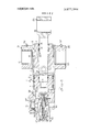
  • FIG. 1 is a cross:sectin view which illustrates an hydraulic actuator with a cushioning means.
  • FIG. 2 is an enlarged cross-section view which illus trates a removably cartridge for operation as a cushioning means in the hydraulic actuator of FIG. I with the poppet valve open.
  • FIG. 3 is an enlarged cross-section view of the end of the hydraulic actuator shown in FIG. 1 with the poppet valve in closed position and the piston near the end of its stroke.
  • FIG. 1 shows the hydraulic actuator in cross section.
  • the hydraulic actuator l includes a cylindrical housing 2 encasing a piston 3 carrying the seals 4 and 5 and a ring 6 for sealing the hydraulic fluid between the chambers 7 and 8.
  • the piston 3 is connected to a piston rod 9 by means of a bolt end 10 and nut 11.
  • the piston rod extends through the end wall 12 which has a cylindrical opening 13 which receives the seals 14 and 15 to seal the chamber 7 of the external side of the hydraulic actuator.
  • the end wall 12 is also provided with a seal 16 on an external periphery engaging the internal periphery of the cylindrical housing 2.
  • the snap ring 17 locks the assembly against an internal force and an external nut 18 threadedly engages the end of the wall 12 to lock assembly against the cylindrical housing 2.
  • the cylindrical housing 2 is also fabricated to the trunnion bearings 19 and 20.
  • the trunnion bearing 19 includes the bearing shell 21 having an opening for receiving lubricant through the grease fitting 22.
  • the trunnion bearing is also fitted with a bearing shell 23 and a similar grease fitting 24 for lubrication of the trunnion bearing 20.
  • the piston rod 9 includes a bearing end 25 which receives the bushing 26 which is adapted for connection to a shaft for carrying the external load on the hydraulic actuator 1.
  • the hydraulic actuator 1 includes a head 27 which is welded at 28 to the cylindrical housing 2.
  • the head 27 also forms a valve chamber 29 which is in communication with the flow port 30 adapted for connection to a source of fluid.
  • the flow of fluid through the port 30 may be of high pressure to extend the piston and expand the chamber 8 or of a low pressure fluid when the fluid is discharged from the expansible chamber 8 through the poppet valve 31.
  • a check valve 32 is also contained within the head 27.
  • the check valve 32 is contained within the compartment 33 and includes the valve seat 34 which has cross passages 35 for receiving fluid from the expansible chamber 8.
  • the valve seat 34 has a threaded portion 36 which threadedly engages the valve support 37 which in turn has a threaded portion 38 which threadedly engages a threaded opening 39 in the head 27.
  • a suitable seal 40 is provided underneath the head 41 of the valve support 37.
  • the valve support 37 carries the valve seat 34 and can be removed as a unit from the head 27 if servicing is desired.
  • the check valve 32 includes a ball 42 and spring 43 normally biasing the check valve to a closed position. Suitable passages are provided to transmit fluid from the cross passages 35 in the valve seat 34 to the cross passages 44 in the valve support 37 which provide communication between the expansible chamber 8 and the compartment 33.
  • the check valve 32 is formed with a peripheral groove 70 to receive the seal 71 to seal the expansible chamber 8 from the valve chamber 29.
  • the poppet valve 31 includes the valve body 45 having a threaded portion 46 which threadedly engages a threaded opening 47 in the head 27 and is removable as a valve cartridge.
  • the valve body 45 also is provided with a threaded interior 48 which threadedly receives the threaded portion 49 of the cap 50.
  • a seal 51 is received within the annular recess 52 to provide a seal between the expansible chamber 8 and the valve chamber 29.
  • the seal 53 between the valve body 45 and the head 27 seals the chamber 29 from the exterior side of the head while the seal 54 provides a seal between the cavity 55 and the exterior side of the hydraulic actuator.
  • the spring seat 57 is seated within the cap 50 and has a stem 58 received within the spring 59.
  • the spring 59 is compressibly positioned between the spring seat 57 and the retainer ring 60.
  • a spring 61 is compressibly positioned between the retainer 60 and the snap ring 62 carried on the plunger 63.
  • the poppet 64 is slidably positionend within the valve body 45 and normally biased to the open position as shown in FIG. 2.
  • the valve body 45 forms a valve seat 65 which engages a conical surface 66 when the poppet valve is in the closed position as shown in FIG. 3.
  • the poppet forms an orifice 67 providing communication between the valve chamber 29 and the expansible chamber 8 when the poppet valve 31 is in the closed position.
  • the snap ring 68 provides a stop to limit the open position of the poppet valve 31.
  • the poppet 64 When the hydraulic actuator is in operation and the piston 3 is in a position remote from the head 27, the poppet 64 is spring biased outwardly by the spring 59 compressed against the retaining ring 60 which engages the inner periphery of valve body 45.
  • the plunger 63 is spring biased outwardly by the spring 61 compressively positioned between the retaining rings 62 and 60. With the plunger and the poppet in the extended position oil can flow freely from the expansible chamber 8 to the valve chamber 29.
  • a hydraulic actuator comprising a cylindrical housing, a head fastened to the end of said cylindrical housing defining a valve chamber communicating with a flow port, a piston slidably received within said cylindrical housing and forming an expansible chamber with said head, a removable valve cartridge mounted in said head including a valve body defining a valve seat, a valve element slidably mounted within said valve body and defining a poppet valve with said valve seat in said body, fastening means on said head and valve cartridge removably fastening said valve cartridge in said valve chamber said valve cartridge controlling fluid flow between said expansible chamber and said valve chamber conduit means through said valve body interconnecting the internal and external portions thereof, means defining an orifice providing restrictive fluid passage across said poppet valve and communicating said expansible chamber with said valve chamber via said conduit means, a relief valve, means supporting said relief valve in said head and passage means within said head communicating said expansible chamber with said relief valve and further passage means within said head communicating said relief valve with said valve chamber to limit peak pressures in said expansible chamber, resilient means interposed
  • a hydraulic actuator as set forth in claim 1 including, a relief valve casing housing said relief valve and fastening means removably supporting said relief valve casing in said head.
  • a hydraulic actuator as set forth in claim 1 including a spring normally biasing said plunger to an extended position for engaging said piston when said piston nears the end of its stroke.
  • valve actuating plunger defines a hollow plunger, means defining a central opening in said valve element for reciprocally receiving said plunger, ports means in said plunger for transmitting fluid from said central opening in said valve element when said plunger is biased by said piston to close said valve.
  • a hydraulic actuator as set forth in claim 1 where said fastening means includes said valve body defining a cylindrical sleeve including a threaded portion, and means defining a cylindrical opening in said head having a threaded portion for receiving said cylindrical sleeve.
  • a hydraulic actuator as set forth in claim 1 including said relief valve positioned in said head to permit fluid flow only from said expansible chamber to said valve chamber to limit peak pressures in said expansible chamber when said piston nears the end of its stroke.
  • valve body defines a sleeve
  • valve element defines said poppet valve mounted within said sleeve
  • poppet valve defines said orifice whereby said orifice and said poppet valve control the flow to and from said expansible chamber in said hydraulic actuator.
Landscapes

  • Engineering & Computer Science (AREA)
  • Physics & Mathematics (AREA)
  • Fluid Mechanics (AREA)
  • Mechanical Engineering (AREA)
  • General Engineering & Computer Science (AREA)
  • Actuator (AREA)

Abstract

A hydraulic cylinder having a reciprocating piston and cushioning means on the end of the cylinder to decelerate the piston as it comes to the end of its stroke. The decelerating means includes a valving means and orifice means to restrict the flow and produce throttling of the hydraulic fluid as the piston nears the end of its stroke.

Description

1 1 Apr. 15, 1975 CUSHIONED HYDRAULIC ACTUATOR [75] Inventor: Herbert Z. Langland, Topeka, Kans.
[73] Assignee: Allis-Chalmers Corporation,
Milwaukee, Wis.
22 Filed: Mar. 2, 1973 211 Appl. No.1 337,531
2,547,861 4/1951 Fletcher 91/406 X 2,783,742 3/1957 Shafer 91/407 X 2,831,933 4/1958 Schrameck et al.. 91/406 X 3,039,485 6/1962 Brohl 251/117 X 3,054,384 9/1962 Darling 91/26 X 3,162,092 12/1964 Corwin 91/407 X 3/1967 Allen 137/5962 X Primary Examiner-Jrwin C. Cohen Assistant ExaminerAbraham l-lershkovitz [52] US. Cl. 91/406; 91/24; 91/31; Attorney, Agent, or Firm-Arthur L. Nelson 91/407; 92/143; 137/596.2; 251/117 [51] Int. Cl. [58] Field of Search 91/404, 405, 406, 407,
9l/25 26, 24, 31; 92/143; 251/l17 X; A hydraulic cylinder havmg a reciprocating piston and 137/5962 X cushioning means on the end of the cylinder to decelerate the piston as it comes to the end of its stroke. [56] References Cited Th? decelerating metanstirtilclutdles a vailvingdmeantshantd on ice means 0 res me e ow an pro uce ro UNITED STATES PATENTS tling of the hydraulic fluid as the piston nears the end 1,891,312 12/1932 Knecht 91/406 X of its Stroke 2,247,201 6/1941 Loos 91/406 X 2,338,845 1/1944 Gunner et a1. 91/406 X 10 Claims, 3 Drawing Figures 37 27 Ill 28 U U r:: 1 Q I PATENIEB RPR 1 5 I975 SHEET 1 2 FMENTEDAFR I SISYS saw 2 pg 2 CUSHIONED HYDRAULIC ACTUATOR This invention relates to a hydraulic cylinder and more particularly to a cushioning means to decelerate the movement of the piston as it nears the end of its stroke.
Hydraulic cylinders are used to perform a number of operations in hydraulic systems used on motor vehicles. 7
Most of the hydraulic cylinders carry a substantial load and during their operation are subjected to inertia forces. This is particularly true of the hydraulic cylinder as it nears the end of its stroke. The load carried by the hydraulic cylinder is often so great that if the load were allowed to force the piston unrestrained to the end of its stroke in the hydraulic cylinder, it may cause irrepairable damage to the cylinder. Shock loading of this type cannot be tolerated in the hydraulic system not only because it may damage the hydraulic cylinder but the load itself may be subjected to excessive inertia forces.
Accordingly, this invention provides a means whereby inertia forces normally produced by the load on the hydraulic cylinder at the end of the piston stroke are substantially reduced or eliminated to prevent damage to the hydraulic cylinder and to provide smooth operation of the hydraulic system in handling the load carried by the hydraulic cylinder. The cushioning means in the hydraulic cylinder is accomplished through throttling of the hydraulic fluid as the piston nears the end of its stroke. The throtting is produced by a valve which is actuated by the piston to close a valve and force fluid through an orifice or a check valve to eliminate the shock and inertia forces suddenly imposed on the hydraulic cylinder as it reaches the end of its stroke.
It is an object of this invention to provide a cushioned hydraulic cylinder or hydraulic actuator for decelerating the movement of the piston near the end of its stroke.
It is another object of this invention to provide a cushioned hydraulic cylinder for decelerating the movement of the piston near the end of its stroke with a cushioning means in a removable cartridge to permit removal of the cartridge for easy repair and servicing.
It is a further object of this invention to provide cushioning means in a hydraulic actuator for throttling the hydraulic fluid through a closing poppet valve in the end of the hydraulic actuator, an orifice, and a check valve to prevent shock loading and high pressures in the hydraulic chamber as the piston nears the end of its stroke.
It is a further object of this invention to provide a cushioned hydraulic actuator to decelerate the piston movement as it nears the end of its stroke by throttling through a closing poppet valve, an orifice, and check valve and to limit high pressures and eliminate high inertia forces as the piston comes to the end of its stroke.
The objects of this invention are accomplished by providing throttling means in the end ofa hydraulic actuator which throttle the fluid as it is discharged from the hydraulic actuator near the end of the piston stroke. The cushioning means includes a poppet valve and orifice in the head of the hydraulic actuator which can be readily removed'for servicing and repair to keep the cushioning means in the best of operating conditions. Together with the poppet valve and an orifice, a check valve is also provided to eliminate any shock or inertia forces from damaging the end of the hydraulic actuator as the piston nears the end of its stroke and particularly when the hydraulic actuator is under a loaded condition.
The preferred embodiment of this invention is illustrated in the attached drawings.
FIG. 1 is a cross:sectin view which illustrates an hydraulic actuator with a cushioning means.
FIG. 2 is an enlarged cross-section view which illus trates a removably cartridge for operation as a cushioning means in the hydraulic actuator of FIG. I with the poppet valve open.
FIG. 3is an enlarged cross-section view of the end of the hydraulic actuator shown in FIG. 1 with the poppet valve in closed position and the piston near the end of its stroke.
) Referring to the drawings, FIG. 1 shows the hydraulic actuator in cross section. The hydraulic actuator l includes a cylindrical housing 2 encasing a piston 3 carrying the seals 4 and 5 and a ring 6 for sealing the hydraulic fluid between the chambers 7 and 8. The piston 3 is connected to a piston rod 9 by means of a bolt end 10 and nut 11. The piston rod extends through the end wall 12 which has a cylindrical opening 13 which receives the seals 14 and 15 to seal the chamber 7 of the external side of the hydraulic actuator.
The end wall 12 is also provided with a seal 16 on an external periphery engaging the internal periphery of the cylindrical housing 2. The snap ring 17 locks the assembly against an internal force and an external nut 18 threadedly engages the end of the wall 12 to lock assembly against the cylindrical housing 2.
The cylindrical housing 2 is also fabricated to the trunnion bearings 19 and 20. The trunnion bearing 19 includes the bearing shell 21 having an opening for receiving lubricant through the grease fitting 22. The trunnion bearing is also fitted with a bearing shell 23 and a similar grease fitting 24 for lubrication of the trunnion bearing 20. v
The piston rod 9 includes a bearing end 25 which receives the bushing 26 which is adapted for connection to a shaft for carrying the external load on the hydraulic actuator 1.
The hydraulic actuator 1 includes a head 27 which is welded at 28 to the cylindrical housing 2. The head 27 together with the piston 3 and the cylindrical housing 2 forms the expansible chamber 8. The head 27 also forms a valve chamber 29 which is in communication with the flow port 30 adapted for connection to a source of fluid. The flow of fluid through the port 30 may be of high pressure to extend the piston and expand the chamber 8 or of a low pressure fluid when the fluid is discharged from the expansible chamber 8 through the poppet valve 31.
A check valve 32 is also contained within the head 27. The check valve 32 is contained within the compartment 33 and includes the valve seat 34 which has cross passages 35 for receiving fluid from the expansible chamber 8. The valve seat 34 has a threaded portion 36 which threadedly engages the valve support 37 which in turn has a threaded portion 38 which threadedly engages a threaded opening 39 in the head 27. A suitable seal 40 is provided underneath the head 41 of the valve support 37. The valve support 37 carries the valve seat 34 and can be removed as a unit from the head 27 if servicing is desired. The check valve 32 includes a ball 42 and spring 43 normally biasing the check valve to a closed position. Suitable passages are provided to transmit fluid from the cross passages 35 in the valve seat 34 to the cross passages 44 in the valve support 37 which provide communication between the expansible chamber 8 and the compartment 33.
The check valve 32 is formed with a peripheral groove 70 to receive the seal 71 to seal the expansible chamber 8 from the valve chamber 29.
The poppet valve 31 includes the valve body 45 having a threaded portion 46 which threadedly engages a threaded opening 47 in the head 27 and is removable as a valve cartridge. The valve body 45 also is provided with a threaded interior 48 which threadedly receives the threaded portion 49 of the cap 50. A seal 51 is received within the annular recess 52 to provide a seal between the expansible chamber 8 and the valve chamber 29. The seal 53 between the valve body 45 and the head 27 seals the chamber 29 from the exterior side of the head while the seal 54 provides a seal between the cavity 55 and the exterior side of the hydraulic actuator.
The spring seat 57 is seated within the cap 50 and has a stem 58 received within the spring 59. The spring 59 is compressibly positioned between the spring seat 57 and the retainer ring 60. Similarly a spring 61 is compressibly positioned between the retainer 60 and the snap ring 62 carried on the plunger 63. The poppet 64 is slidably positionend within the valve body 45 and normally biased to the open position as shown in FIG. 2. The valve body 45 forms a valve seat 65 which engages a conical surface 66 when the poppet valve is in the closed position as shown in FIG. 3.
The poppet forms an orifice 67 providing communication between the valve chamber 29 and the expansible chamber 8 when the poppet valve 31 is in the closed position.
The snap ring 68 provides a stop to limit the open position of the poppet valve 31.
The operation of the cushioning means will be described in the following paragraphs.
When the hydraulic actuator is in operation and the piston 3 is in a position remote from the head 27, the poppet 64 is spring biased outwardly by the spring 59 compressed against the retaining ring 60 which engages the inner periphery of valve body 45. The plunger 63 is spring biased outwardly by the spring 61 compressively positioned between the retaining rings 62 and 60. With the plunger and the poppet in the extended position oil can flow freely from the expansible chamber 8 to the valve chamber 29.
As the piston moves near the end of its stroke it contacts the plunger 63. The poppet 64 then becomes unbalanced due to the load induced by the plunger spring 61. As the poppet 64 moves toward the spring retainer 57 the oil .in expansible chamber 8 assists the spring in forcing the poppet 64 to seat on the valve seat 65 of the valve body 45 due to the pressure drop caused by a reduced outlet area in the poppet valve 32. After the poppet 64 has seated on the seat 65 oil can be exhausted through the orifice 67 in the poppet 64 or through the relief valve 32. Normally the relief valve opens after the poppet has seated. Relief valve 32 then reseats. The remaining oil is forced through the orifice 67. When the poppet seats on the seat 65 of the valve body 45 the plunger 63 will continue to retract through the remainder of the piston stroke and the load against the springs 61 remains as the resilience of the spring allows for this overtravel. The piston stroke is such that the piston rod 9 stops short of the striking of the poppet 64.
To extend the piston rod 9 and the piston 3 in the hydraulic actuator hydraulic fluid flows through the flow port 30 into the valve chamber 29 opening the poppet valve 31 and flowing into the expansible chamber 8. The oil pressure unseats the poppet valve 31 expanding the plunger springs 61 as the oil enters the expansible chamber 8 through the valve. As the piston rod moves with the piston 3 the piston 3 moves out until the retaining ring 62 engages the radical flange 73 of the poppet 64. As the piston 3 and rod 9 move to the extended position within the hydraulic actuator the poppet 64 of the poppet valve 31 fully opens with snap ring 68 engaging surface of valve body 45. The plunger 63 within the poppet 64 extends to its fully extended position and fluid flows freely through the flow port 30, the valve chamber 29 and the poppet valve 31 into the expansible chamber 8.
The embodiments of the invention in which an exclusive property or privilege is claimed are defined as follows:
l. A hydraulic actuator comprising a cylindrical housing, a head fastened to the end of said cylindrical housing defining a valve chamber communicating with a flow port, a piston slidably received within said cylindrical housing and forming an expansible chamber with said head, a removable valve cartridge mounted in said head including a valve body defining a valve seat, a valve element slidably mounted within said valve body and defining a poppet valve with said valve seat in said body, fastening means on said head and valve cartridge removably fastening said valve cartridge in said valve chamber said valve cartridge controlling fluid flow between said expansible chamber and said valve chamber conduit means through said valve body interconnecting the internal and external portions thereof, means defining an orifice providing restrictive fluid passage across said poppet valve and communicating said expansible chamber with said valve chamber via said conduit means, a relief valve, means supporting said relief valve in said head and passage means within said head communicating said expansible chamber with said relief valve and further passage means within said head communicating said relief valve with said valve chamber to limit peak pressures in said expansible chamber, resilient means interposed between said valve body and said valve element normally biasing said valve element to an open position, a valve actuating plunger, resilient means interposed between said valve element and saidplunger, said plunger engaging said piston to close said poppet valve and provide restrictive fluid flow through said orifice when said piston nears the end of its stroke and thereby cushioning the movement of the piston by restricting the flow of fluid from said expansible chamber.
2. A hydraulic actuator as set forth in claim 1 including, a relief valve casing housing said relief valve and fastening means removably supporting said relief valve casing in said head.
3. A hydraulic actuator as set forth in claim 1 wherein said relief valve defines a ball check valve,
means removably fastening said relief valve in said head, said relief valve providing relief of peak pressures in said expansible chamber when said piston nears the end of its stroke.
4. A hydraulic actuator as set forth in claim 1 wherein said valve element defines said orifice.
5. A hydraulic actuator as set forth in claim 1 including a spring normally biasing said plunger to an extended position for engaging said piston when said piston nears the end of its stroke.
6. A hydraulic actuator as set forth in claim 1 wherein said valve actuating plunger defines a hollow plunger, means defining a central opening in said valve element for reciprocally receiving said plunger, ports means in said plunger for transmitting fluid from said central opening in said valve element when said plunger is biased by said piston to close said valve.
7. A hydraulic actuator as set forth in claim 1 where said fastening means, includes said valve body defining a cylindrical sleeve including a threaded portion, and means defining a cylindrical opening in said head having a threaded portion for receiving said cylindrical sleeve.
8. A hydraulic actuator as set forth in claim 1 including said relief valve positioned in said head to permit fluid flow only from said expansible chamber to said valve chamber to limit peak pressures in said expansible chamber when said piston nears the end of its stroke.
9. A hydraulic actuator as set forth in claim 1, said head including means centrally supporting said valve cartridge in said hydraulic actuator.
10. A hydraulic actuator as set forth in claim 1 wherein said valve body defines a sleeve, said valve element defines said poppet valve mounted within said sleeve, said poppet valve defines said orifice whereby said orifice and said poppet valve control the flow to and from said expansible chamber in said hydraulic actuator.

Claims (10)

1. A hydraulic actuator comprising a cylindrical housing, a head fastened to the end of said cylindrical housing defining a valve chamber communicating with a flow port, a piston slidably received within said cylindrical housing and forming an expansible chamber with said head, a removable valve cartridge mounted in said head including a valve body defining a valve seat, a valve element slidably mounted within said valve body and defining a poppet valve with said valve seat in said body, fastening means on said head and valve cartridge removably fastening said valve cartridge in said valve chamber said valve cartridge controlling fluid flow between said expansible chamber and said valve chamber conduit means through said valve body interconnecting the internal and external portions thereof, means defining an orifice providing restrictive fluid passage across said poppet valve and communicating said expansible chamber with said valve chamber via said conduit means, a relief valve, means supporting said relief valve in said head and passage means within said head communicating said expansible chamber with said relief valve and further passage means within said head communicating said relief valve with said valve chamber to limit peak pressures in said expansible chamber, resilient means interposed between said valve body and said valve element normally biasing said valve element to an open position, a valve actuating plunger, resilient means interposed between said valve element and said plunger, said plunger engaging said piston to close said poppet valve and provide restrictive fluid flow through said orifice when said piston nears the end of its stroke and thereby cushioning the movement of the piston by restricting the flow of fluid from said expansible chamber.
2. A hydraulic actuator as set forth in claim 1 including, a relief valve casing housing said relief valve and fastening means removably supporting said relief valve casing in said head.
3. A hydraulic actuator as set forth in claim 1 wherein said relief valve defines a ball check valve, means removably fastening said relief valve in said head, said relief valve providing relief of peak pressures in said expansible chamber when said piston nears the end of its stroke.
4. A hydraulic actuator as set forth in claim 1 wherein said valve element defines said orifice.
5. A hydraulic actuator as set forth in claim 1 including a spring normally biasing said plunger to an extended position for engaging said piston when said piston nears the end of its stroke.
6. A hydraulic actuator as set forth in claim 1 wherein said valve actuating plunger defines a hollow plunger, means defining a central opening in said valve element for reciprocally receiving said plunger, ports means in said plunger for transmitting fluid from said central opening in said valve element when said plunger is biased by said piston to close said valve.
7. A hydraulic actuator as set forth in claim 1 where said fastening means, includes said valve body defining a cylindrical sleeve including a threaded portion, and means defining a cylindrical opening in said head having a threaded portion for receiving said cylindrical sleeve.
8. A hydraulic actuator as set forth in claim 1 including said relief valve positioned in said head to permit fluid flow only from said expansible chamber to said valve chamber to limit peak pressures in said expansible chamber when said piston nears the end of its stroke.
9. A hydraulic actuator as set forth in claim 1, said head including means centrally suppOrting said valve cartridge in said hydraulic actuator.
10. A hydraulic actuator as set forth in claim 1 wherein said valve body defines a sleeve, said valve element defines said poppet valve mounted within said sleeve, said poppet valve defines said orifice whereby said orifice and said poppet valve control the flow to and from said expansible chamber in said hydraulic actuator.
US337531A 1973-03-02 1973-03-02 Cushioned hydraulic actuator Expired - Lifetime US3877344A (en)

Priority Applications (2)

Application Number Priority Date Filing Date Title
US337531A US3877344A (en) 1973-03-02 1973-03-02 Cushioned hydraulic actuator
CA184,930A CA992434A (en) 1973-03-02 1973-11-02 Cushioned hydraulic actuator

Applications Claiming Priority (1)

Application Number Priority Date Filing Date Title
US337531A US3877344A (en) 1973-03-02 1973-03-02 Cushioned hydraulic actuator

Publications (1)

Publication Number Publication Date
US3877344A true US3877344A (en) 1975-04-15

Family

ID=23320907

Family Applications (1)

Application Number Title Priority Date Filing Date
US337531A Expired - Lifetime US3877344A (en) 1973-03-02 1973-03-02 Cushioned hydraulic actuator

Country Status (2)

Country Link
US (1) US3877344A (en)
CA (1) CA992434A (en)

Cited By (16)

* Cited by examiner, † Cited by third party
Publication number Priority date Publication date Assignee Title
WO1980001097A1 (en) * 1978-11-20 1980-05-29 Caterpillar Tractor Co Cushioning device for fluid jacks
US4250793A (en) * 1978-11-20 1981-02-17 Caterpillar Tractor Co. Cushioning device for fluid jacks
US4257314A (en) * 1977-03-30 1981-03-24 Deschner Richard E Apparatus for improved motion control
US4397218A (en) * 1980-12-23 1983-08-09 Allis-Chalmers Corporation Cushion stop for hydraulic cylinder
US4440068A (en) * 1981-03-19 1984-04-03 Pneumo Corporation Hydraulic cowl door actuator with anti-vibration loading device, and assembly employing same
FR2556856A1 (en) * 1983-12-16 1985-06-21 United Technologies Corp PERFECTLY PIVOT SPEED CONTROL SYSTEM FOR A FLUID ACTUATOR
GB2164704A (en) * 1984-09-25 1986-03-26 Fadini Meccanica A device for braking the piston of a hydraulic jack at the end of its stroke, in particular a jack for effecting the opening and closing of gates, doors or the like
US4676139A (en) * 1985-09-17 1987-06-30 Centrifugal Piston Expander, Inc. Valve mechanism for operating a piston within a cylinder
US4957167A (en) * 1989-04-14 1990-09-18 Halliburton Co. Retrievable fluid control valve with damping
US5003729A (en) * 1988-10-11 1991-04-02 Ppg Industries, Inc. Support system for abrasive jet cutting
US5680913A (en) * 1996-11-22 1997-10-28 Caterpillar Inc. Snubber for a hydraulic motor
US5784947A (en) * 1992-06-22 1998-07-28 Bayne Machine Works, Inc. Residential refuse collection cart lifter with universal features
US6557456B2 (en) 2001-05-24 2003-05-06 The Raymond Corporation Cushioned actuator
CN104047924A (en) * 2014-07-08 2014-09-17 常州市新墅机床数控设备有限公司 Locking oil cylinder structure with stroke tail end buffered
EP3825557A1 (en) * 2019-11-22 2021-05-26 Goodrich Actuation Systems SAS Hydraulic actuators
WO2025162565A1 (en) * 2024-01-31 2025-08-07 Safran Landing Systems Linear actuator with damper

Citations (10)

* Cited by examiner, † Cited by third party
Publication number Priority date Publication date Assignee Title
US1891312A (en) * 1932-01-21 1932-12-20 Perfection Steel Body Co Hydraulic hoist for dumping trucks
US2247201A (en) * 1937-11-30 1941-06-24 Westinghouse Electric & Mfg Co Circuit breaker operating means
US2338845A (en) * 1941-10-10 1944-01-11 Curtiss Wright Corp Hydraulic piston snubber
US2547861A (en) * 1949-10-26 1951-04-03 Deere Mfg Co Variable position control for hydraulic systems
US2783742A (en) * 1954-11-22 1957-03-05 Shafer Valve Co Automatic pressure reducing means for hydraulic gate valve operator
US2831933A (en) * 1956-03-02 1958-04-22 Westinghouse Electric Corp Circuit interrupters
US3039485A (en) * 1962-06-19 Fuel system pressure modulator
US3054384A (en) * 1961-01-12 1962-09-18 Cessna Aircraft Co Piston velocity governor
US3162092A (en) * 1962-07-09 1964-12-22 Tomkins Johnson Company Cylinder cushion structure
US3309852A (en) * 1964-01-20 1967-03-21 Fawick Corp Hydraulic system and valve arrangement therein

Patent Citations (10)

* Cited by examiner, † Cited by third party
Publication number Priority date Publication date Assignee Title
US3039485A (en) * 1962-06-19 Fuel system pressure modulator
US1891312A (en) * 1932-01-21 1932-12-20 Perfection Steel Body Co Hydraulic hoist for dumping trucks
US2247201A (en) * 1937-11-30 1941-06-24 Westinghouse Electric & Mfg Co Circuit breaker operating means
US2338845A (en) * 1941-10-10 1944-01-11 Curtiss Wright Corp Hydraulic piston snubber
US2547861A (en) * 1949-10-26 1951-04-03 Deere Mfg Co Variable position control for hydraulic systems
US2783742A (en) * 1954-11-22 1957-03-05 Shafer Valve Co Automatic pressure reducing means for hydraulic gate valve operator
US2831933A (en) * 1956-03-02 1958-04-22 Westinghouse Electric Corp Circuit interrupters
US3054384A (en) * 1961-01-12 1962-09-18 Cessna Aircraft Co Piston velocity governor
US3162092A (en) * 1962-07-09 1964-12-22 Tomkins Johnson Company Cylinder cushion structure
US3309852A (en) * 1964-01-20 1967-03-21 Fawick Corp Hydraulic system and valve arrangement therein

Cited By (21)

* Cited by examiner, † Cited by third party
Publication number Priority date Publication date Assignee Title
US4257314A (en) * 1977-03-30 1981-03-24 Deschner Richard E Apparatus for improved motion control
WO1980001097A1 (en) * 1978-11-20 1980-05-29 Caterpillar Tractor Co Cushioning device for fluid jacks
US4250793A (en) * 1978-11-20 1981-02-17 Caterpillar Tractor Co. Cushioning device for fluid jacks
US4397218A (en) * 1980-12-23 1983-08-09 Allis-Chalmers Corporation Cushion stop for hydraulic cylinder
US4440068A (en) * 1981-03-19 1984-04-03 Pneumo Corporation Hydraulic cowl door actuator with anti-vibration loading device, and assembly employing same
FR2556856A1 (en) * 1983-12-16 1985-06-21 United Technologies Corp PERFECTLY PIVOT SPEED CONTROL SYSTEM FOR A FLUID ACTUATOR
US4597319A (en) * 1983-12-16 1986-07-01 United Technologies Corporation Fluid actuator slew rate control
GB2164704A (en) * 1984-09-25 1986-03-26 Fadini Meccanica A device for braking the piston of a hydraulic jack at the end of its stroke, in particular a jack for effecting the opening and closing of gates, doors or the like
US4676139A (en) * 1985-09-17 1987-06-30 Centrifugal Piston Expander, Inc. Valve mechanism for operating a piston within a cylinder
US5003729A (en) * 1988-10-11 1991-04-02 Ppg Industries, Inc. Support system for abrasive jet cutting
US4957167A (en) * 1989-04-14 1990-09-18 Halliburton Co. Retrievable fluid control valve with damping
US5784947A (en) * 1992-06-22 1998-07-28 Bayne Machine Works, Inc. Residential refuse collection cart lifter with universal features
US6167795B1 (en) 1992-06-22 2001-01-02 Bayne Machine Works, Inc. Container box and lifter features
US5680913A (en) * 1996-11-22 1997-10-28 Caterpillar Inc. Snubber for a hydraulic motor
US6557456B2 (en) 2001-05-24 2003-05-06 The Raymond Corporation Cushioned actuator
CN104047924A (en) * 2014-07-08 2014-09-17 常州市新墅机床数控设备有限公司 Locking oil cylinder structure with stroke tail end buffered
CN104047924B (en) * 2014-07-08 2016-01-13 常州市新墅机床数控设备有限公司 The locking cylinder structure of end of travel buffering
EP3825557A1 (en) * 2019-11-22 2021-05-26 Goodrich Actuation Systems SAS Hydraulic actuators
US11085467B2 (en) 2019-11-22 2021-08-10 Goodrich Actuation Systems Sas Hydraulic actuators
WO2025162565A1 (en) * 2024-01-31 2025-08-07 Safran Landing Systems Linear actuator with damper
WO2025162954A1 (en) * 2024-01-31 2025-08-07 Safran Landing Systems Linear actuator with damper

Also Published As

Publication number Publication date
CA992434A (en) 1976-07-06

Similar Documents

Publication Publication Date Title
US3877344A (en) Cushioned hydraulic actuator
US4515343A (en) Arrangement for electromagnetically operated actuators
US5517898A (en) Pneumatic cylinder utilizing cushioning sleeves, quick exhaust valves and quick supply valves
US2379750A (en) Shock absorber
US4550899A (en) Pneumatic spring
US4424737A (en) Stroke cushioning apparatus for hydraulic cylinders
US5107970A (en) High pressure sealing system and method
US10520055B2 (en) Recoil suppressing hydraulic damper for a train coupler
US3277837A (en) Pump cylinder closing means
US2345306A (en) Fluid controlled valve
US5988608A (en) Piston-cylinder unit having a sealing valve
US4397218A (en) Cushion stop for hydraulic cylinder
EP2236840B1 (en) Booster valve
US20060290037A1 (en) Gas spring
US3036669A (en) Hydraulic shock absorber with compression cut-off
US7870818B2 (en) Piston for a piston-cylinder unit
GB2115106A (en) Adjusting hydraulic dampers
US4310290A (en) Radial piston pump
US5331998A (en) Radial valve with unloader assembly for gas compressor
US2397117A (en) Unloader valve
US5992584A (en) Dashpot for power cylinder
US6205964B1 (en) Damping device for movable masses, preferably for electromagnetic systems
US4523515A (en) Valve operating cylinder unit
US3468336A (en) Hydraulic control valve for high pressure hydraulic applications
US6651547B2 (en) Guide for the piston rod of a piston-cylinder assembly

Legal Events

Date Code Title Description
AS Assignment

Owner name: CONNECTICUT NATIONAL BANK THE, A NATIONAL BANKING

Free format text: SECURITY INTEREST;ASSIGNOR:ALLIS-CHALMERS CORPORATION A DE CORP.;REEL/FRAME:004149/0001

Effective date: 19830329

Owner name: WOODS KATHLEEN D., AS TRUSTEE

Free format text: SECURITY INTEREST;ASSIGNOR:ALLIS-CHALMERS CORPORATION A DE CORP.;REEL/FRAME:004149/0001

Effective date: 19830329

AS Assignment

Owner name: CDI SALES CORP., 900 6TH AVE., S.E., MINNEAPOLIS,

Free format text: ASSIGNMENT OF ASSIGNORS INTEREST.;ASSIGNOR:ALLIS-CHALMERS CORPORATION;REEL/FRAME:004259/0870

Effective date: 19840312