US3926475A - Machine and method for manufacturing brooms from plastic fibers - Google Patents
Machine and method for manufacturing brooms from plastic fibers Download PDFInfo
- Publication number
- US3926475A US3926475A US501331A US50133174A US3926475A US 3926475 A US3926475 A US 3926475A US 501331 A US501331 A US 501331A US 50133174 A US50133174 A US 50133174A US 3926475 A US3926475 A US 3926475A
- Authority
- US
- United States
- Prior art keywords
- fibers
- bundle
- broom
- bundles
- support
- Prior art date
- Legal status (The legal status is an assumption and is not a legal conclusion. Google has not performed a legal analysis and makes no representation as to the accuracy of the status listed.)
- Expired - Lifetime
Links
- 239000000835 fiber Substances 0.000 title claims abstract description 76
- 244000007853 Sarothamnus scoparius Species 0.000 title claims abstract description 52
- 229920003023 plastic Polymers 0.000 title claims description 13
- 239000004033 plastic Substances 0.000 title claims description 13
- 238000000034 method Methods 0.000 title claims description 10
- 238000004519 manufacturing process Methods 0.000 title abstract description 9
- 238000010438 heat treatment Methods 0.000 claims abstract description 20
- 238000002844 melting Methods 0.000 claims abstract description 13
- 230000008018 melting Effects 0.000 claims abstract description 13
- 238000001816 cooling Methods 0.000 claims description 10
- 238000003825 pressing Methods 0.000 claims description 3
- 238000000465 moulding Methods 0.000 claims description 2
- 229920002457 flexible plastic Polymers 0.000 abstract description 5
- 229920001225 polyester resin Polymers 0.000 abstract description 2
- 239000004645 polyester resin Substances 0.000 abstract description 2
- 208000027418 Wounds and injury Diseases 0.000 description 1
- 239000003795 chemical substances by application Substances 0.000 description 1
- 230000006835 compression Effects 0.000 description 1
- 238000007906 compression Methods 0.000 description 1
- 238000010276 construction Methods 0.000 description 1
- 230000006378 damage Effects 0.000 description 1
- 238000000151 deposition Methods 0.000 description 1
- 239000012530 fluid Substances 0.000 description 1
- 208000014674 injury Diseases 0.000 description 1
- 239000000463 material Substances 0.000 description 1
- 238000002360 preparation method Methods 0.000 description 1
- 102220020371 rs151020603 Human genes 0.000 description 1
Images
Classifications
-
- A—HUMAN NECESSITIES
- A46—BRUSHWARE
- A46D—MANUFACTURE OF BRUSHES
- A46D7/00—Pressing devices for making brooms composed of brushwood or the like
Definitions
- [ PP 501,331 fibers are first formed into bundles of a predetermined size wherein one end of the bundle is engaged by a 52 US. Cl 300 21; 300 12 heating element, PtefetahlY electrical and melted in i51i 1m. (:1.
- FIG.1 A first figure.
- the present invention relates to a machine and a method of construction brooms, brushes and like articles made from elongated flexible plastic fibers, or strands.
- brooms For convenience, later references to brooms alone will be intended to include brushes and any like articles that may be manufactured by the same or similar apparatus, and the method disclosed herein.
- One object of the invention is to provide a new and novel machine for making brooms and brushes from elongated flexible plastic fibers whereby production may be substantially automatic.
- Another object of the invention is to provide a method of producing brooms and the like in which a minimum number of operations are used.
- a further object of the invention is'to eliminate the necessity of using additional materials for securing the fibers to the end of the handle of the broom.
- Another object of the invention is to provide a machine or apparatus that will reduce the requirement of specialized labor in the making of this type of broom.
- Another object of the invention is to provide an apparatus that will greatly reduce the possibility of injury to persons in this type of work by reducing the number of present day single manual operations.
- Still a further object of the invention is to provide a new method of making brooms of this type.
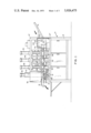
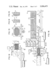
- FIG. 1 is a side elevation view of the machine.
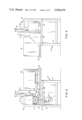
- FIG. 2 is an elevational view of the rear end of the machine.
- FIG. 3 is an elevational view of the front end of the machine.
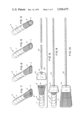
- FIG. 4 is a perspective view of a bundle of bound broom fibers having at least one end free of said bindmg.
- FIG. 5 is a perspective view of a bundle of broom fibers having the unbound end of the bundle of slightly oval shape.
- FIG. 6 is a perspective view of a bundle of bound broom fibers having the oval end of the broom fibers shaped into substantially rectangular form.
- FIG. 7 is a perspective view of a bundle of bound broom fibers showing a recess extending inwardly from the rectangular shaped end of the bundle.
- FIG. 8 is an exploded view in elevation of a bundle of broom fibers, a cover for the rectangular end of the bundle and a handle in position to be inserted through the cover and into the recess formed in the rectangular portion of the bundle.
- FIG. 9 is a view in elevation of the assembled bundle of the fibers, the cover and the handle.
- FIG. 10 is a view in elevation of the assembly shown in FIG. 9 having the binding removed from the bundle of fibers and the free end of the fibers formed into rectangular shape to provide a broom.
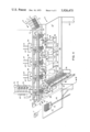
- FIG. 11 is a mechanical schematic perspective view of the machine.
- FIG. 12 is an enlarged view in side elevation of a heating unit for heating the unbound end of the bundle of fibers showing its movable support and the means for operating the said support.
- FIG. 13 is a sectional view taken on line 1313 of FIG. 12.
- FIG. 14 is a sectional view taken on line 1414 of FIG. 13.
- FIG. 15 is a sectional view of a modified form of heating unit.
- FIG. 16 is a sectional view taken on line 16-16 of FIG. 11 illustrating the manner in which the cover and bundle are attached to the bundle of fibers.
- the fibers are cut to a predetermined length and bound in round bundles 6 of such size as to form a single brooms, as shown in FIGS. 4 to 10.
- a binding 7 of any convenient type. It will be noted that the fibers are not bound adjacent one end of the bundle for the reason to be hereinafter referred to.
- the intermediate section 10'' is in the form of a horizontal bed on which is located a number of machine elements used in the making of the broom which will be referred to hereinafter in more detail.
- the frame supports a hopper 12 located at the front end of the machine into which the bundles 6 off bound fibers are placed to be fed into the machine.
- the bundles 6 are fed onto a vertically movable bundle support 14 in spaced relationship and are moved along the support in a step-by-step movement, having a back plate 21 guiding the bound ends of the bundles.
- bundle support 14 is shown in the form of a horizontal table, the bundles may be supported on a conveyor or other suitable means which may be operated in a step-by-step movement.
- the bundles are moved by a plurality of pawls 16 hingedly supported on reciprocating bars 18.
- the pawls are hinged to move from a position perpendicular to the bundle support 14 to a point at least parallel with the bundle support in the direction of the rear of the machine, whereby they will engage the bundle of fibers when the bar 18 moves from the rear of the machine, and pass over the bundles when the bar 18 is moved towards the front of the machine.
- the location of the pawls and the distance of the travel of the reciprocating bars 18 are so arranged that the pawls will place the bundle at a predetermined location along the bundle supporting table 14 which are designated as stations B, C, D and E.
- elongated spring-loaded bars 20 Positioned above the bundle support 14 at a point substantially that of the diameter of the bundles 6 are elongated spring-loaded bars 20 adapted to bear against the upper side of the bundles as they are moved along the table 14 from one station to another.
- the pawls 16 first move the bundle along the table 14 to station B.
- the table 14 is moved down to its lowest point by a rack 22 and a pinion 24 rotatable by an air cylinder 26 as shown in FIG. 2.
- the end 6' of the bundle is lowered into a lower half die 28.
- an upper half die 30 Positioned above the lower half die is an upper half die 30 supported upon members 31 and 31 carried upon an operating means associated with an air cylinder 32, which in turn is supported on the upper section of the frame.
- the bundles of fibers are so positioned in the dies as to allow a predetermined amount of the fiber ends to 3 extend beyond the face of the dies to be engaged by a heating unit 34.
- the support 36 carrying the heating unit 34 is moved along a dovetail slot 38 by means connected to an air cylinder 40 (see FIG. 12) to cause the heating unit 34 to engage the extended ends of the fibers for a predetermined period, melting the end of the fibers into a continuous mass in depth which when cooled will form a rigid mass for the broom along the end 6' of the bundle.
- the air cylinder 40 moves the heating unit support 36 and the heating unit 34 out of contact with the ends of the fibers.
- the heating unit 34 is shown best in FIGS. 13, 14 and 15.
- One form of the face 34 of the heating unit shown in FIG. 14 is provided with short extensions 15, and in FIG. the die face 34 is shown with longer extensions 17. These extensions may be of any desired length for melting the ends of the fibers in depth.
- the heating unit is provided with means 19 for carrying heating elements for the heating unit.
- the air cylinder 32 will operate to raise the upper half die from its contact position with the lower stationary half die 28 in order that the bundle, including its melted end 6, may be moved to the next station.
- the bundle supporting table 14 being movable vertically for a predetermined distance by the apparatus mentioned hereinbefore, is moved vertically upward a sufficient distance to remove the melted end 6' of the fibers from the lower half die 28 whereby the bars 18 are set in reciprocal motion by an appropriate air cylinder (not shown), moving the bundle from its position at station B to station C.
- a stationary second lower half die 44 into which the previously melted end 6 of the bundle 6 is placed by operating the bundle supporting table again downwardly to its lowest position.
- a second upper half die 46 is supported on members 47 and 47 operated by an air cylinder 48. When the cylinder 48 is operated it will cause the second upper half die 46 to move downwardly and engage the lower stationary half die 44.
- These two half dies 44 and 46 are more elongated in shape to give a rectangular form to the shoulder of the broom with a predetermined thickness best shown in FIGS. 6 and 7.
- an outer end-forming die 50 carried by a movable support 52 within a dovetail slot 53 is moved by means associated within an air cylinder similar to that described for moving the heating unit support 36 whereby the support 52 and the end-forming die 50 are moved perpendicular to the previously melted end surface 6' of the bundle, which surface has by this time cooled to a point where the melted end has reached a semi-plastic state wherein the end-forming die 50 shapes and forms the outer surface of the semi-plastic mass in its final shape.
- the air cylinder will operate to retract the surface forming member 50 to its holding position out of contact with the shoulder and into position for the next bundle, and the cylinder 48 will operate to raise the upper half die 46 upwardly and out of contact with the lower half die 44. Again the table 14 will be raised to its upper position and the reciprocating bars 18 will be operated whereby 4 the pawls 16 will engage the bundles on the table 14 moving them to their next respective station.
- the bundle is lowered into the lower stationary half die 54 by the lowering of the table 14 as previously described.
- the air cylinder 56 having means 57 and 57' connecting the cylinder with the upper half die 58, will operate to move the upper half die 58 downwardly in contact with the lower stationary half die 54.
- the shape and size of these half dies 54 and 58 are substantially the same as the size and shape of the half dies 44 and 46.
- an elongated electrically heated stem 59 Fixedly secured to a support 60.
- the stem support 60 is slidably positioned in a dovetail slot 63 similar to that described for supports 36 and 52 and is movable by an appropriate air cylinder (not shown). This support moves the heated stem perpendicular to and centrally of the die opening and the stem is adapted to engage the molded end of the fibers when the die members 54 and 58 engage the molded end 6' forming a recess 61 of a predetermined size and depth therein for receiving the end 42 of the handle 42.
- the half dies at station E are of a slightly modified form.
- the lower half die 62 is provided with an associated holding member 64 and is spring loaded as shown at 65 in FIG. 16.
- the lower half die 62 is supported upon a vertically movable support 63.
- the upper half die 66 is also provided with a holding member 69 which is also spring-loaded by the spring 70 shown in FIG. 16.
- the holding member 69 is positioned to extend below the lower surface of the upper half die 66 in order that the hold-down member will first contact the bundle 6 and aid in holding the shoulder parallel with the bundle supporting table 14.
- These hold-down members 64 and 69 are spaced inwardly from the outer surface 6' of the molded shoulder and will allow the lower and upper dies 62 and 66 to be spaced outwardly from the sides of the rectangular molded area 6' a predetermined distance for allowing room for applying the cover 73 over the outer surfaces of the molded shoulder.
- the spring 65 is arranged to normally hold the holding member 64 in its upper position relative to the lower half die member 62.
- the holding member is adapted to contact the bundle first when the molded end of the bundle is deposited over the lower half die for holding the rectangular shoulder parallel with the bundle supporting table 14.
- the upper half die 66 is moved downwardly by the air cylinder 68 to a point where the holding member 69, which is held downwardly by the compression spring 70, is firmly in contact with the upper side of the bundle.
- These holding members 64 and 69 hold the molded shoulders in position to receive the end of the handle into the recess 61.
- a chute 72 Positioned on the frame at station E and leading to a point adjacent the molded shoulder is a chute 72 for receiving a number of covers or caps 73 for placement over the molded shoulder.
- cover members 73 are shown best in FIG. 11 and 16 and are adapted to fit snugly over the shoulder 6' of the broom having a central opening 74 therein for admitting the end 42 of the handle 42.
- a hopper 76 Positioned outwardly from the cover chute 72 is a hopper 76 for depositing a number of handles 42.
- the handles are fed one at a time to a means 78 and 79 for moving the inner end 42 of the handle through the opening 74 in the cover and into the recess 61 in the shoulder 6' of the broom.
- an air cylinder 80 will operate the members 98 and 99 engaging the cover 73 moving it over the shoulder of the broom.
- the air cylinder 68 is further operated to cause the die 66 to engage the upper side of the cover in the area of the shoulder, and the cylinder 67 is operated to cause the lower half die 62 to engage the lower surface of the cover 73 finally pressing the shoulder to the desired rectangular form should it have been distorted in forming the recess and inserting the end of the handle therein.
- This final clamping of the dies 62 and 66 also presses the melted mass remaining around the sides of the recess formed by the stem element 59 and forms the recess tightly about the end of the handle, after which the air cylinder 68 raises the upper half die 66 and its associate hold down member 69 upwardly out of the way of the bundle and at the same time the air cylinder 67 operates to move the lower half die 62 and the hold-down member 64 out of contact with the lower side of the bundle, whereby the bundle is again raised and moved by the pawls to another station (not shown) or out of the machine.
- the time element for each station is the same as that requied for the melting operation at station B.
- a machine for making brooms from predetermined size bundles of flexible elongated plastic fibers comprising:
- an electrically heated unit positioned outwardly from the fixed end of the fibers and means for supporting and moving the heated unit parallel with the said elongated fibers to engage the fixed end of the fibers for a predetermined period during one of the intervals between the step-by-step movement to form a unitary melted mass of a predetermined depth;
- an elongated electrically heated element normally held outwardly and perpendicular to the outer surface of the cooling melting mass, means for supporting and moving the heated element into engagement with the cooling melted mass to form a recess of predetermined depth within the cooling melted mass for receiving one end of a handle member;
- the bundle supporting means is provided with means for raising the supporting means when the bundles are being moved along the support means and lowering the support means when the bundle is opposite one of the stations.
- the means for moving the bundles is in the form of a reciprocating bar having a plurality of pawls hinged thereto having a limited movement from a point substantially perpendicular to the bundle support to a point substantially parallel with the said bar in the direction toward the rear of the machine.
- a method for automatically producing brooms from elongated plastic fibers comprising the steps:
Landscapes
- Life Sciences & Earth Sciences (AREA)
- Engineering & Computer Science (AREA)
- Wood Science & Technology (AREA)
- Yarns And Mechanical Finishing Of Yarns Or Ropes (AREA)
Priority Applications (3)
| Application Number | Priority Date | Filing Date | Title |
|---|---|---|---|
| US501331A US3926475A (en) | 1974-08-28 | 1974-08-28 | Machine and method for manufacturing brooms from plastic fibers |
| CA233,601A CA1029772A (fr) | 1974-08-28 | 1975-08-18 | Machine et methode pour la fabrication de balais a l'aide de fibres plastiques |
| IT51060/75A IT1041520B (it) | 1974-08-28 | 1975-08-26 | Macchina e metodo di fabbricazione di scope e simili |
Applications Claiming Priority (1)
| Application Number | Priority Date | Filing Date | Title |
|---|---|---|---|
| US501331A US3926475A (en) | 1974-08-28 | 1974-08-28 | Machine and method for manufacturing brooms from plastic fibers |
Publications (1)
| Publication Number | Publication Date |
|---|---|
| US3926475A true US3926475A (en) | 1975-12-16 |
Family
ID=23993093
Family Applications (1)
| Application Number | Title | Priority Date | Filing Date |
|---|---|---|---|
| US501331A Expired - Lifetime US3926475A (en) | 1974-08-28 | 1974-08-28 | Machine and method for manufacturing brooms from plastic fibers |
Country Status (3)
| Country | Link |
|---|---|
| US (1) | US3926475A (fr) |
| CA (1) | CA1029772A (fr) |
| IT (1) | IT1041520B (fr) |
Cited By (2)
| Publication number | Priority date | Publication date | Assignee | Title |
|---|---|---|---|---|
| US4697851A (en) * | 1985-11-19 | 1987-10-06 | Shinwa Seisakusho Co., Ltd. | Method of manufacturing fiber bundles for use in brushes |
| US4979782A (en) * | 1988-06-15 | 1990-12-25 | Coronet-Werke Heinrich Schlerf Gmbh | Process and apparatus for production of bristle products |
Citations (3)
| Publication number | Priority date | Publication date | Assignee | Title |
|---|---|---|---|---|
| US2059530A (en) * | 1935-12-21 | 1936-11-03 | Harry J Lay | Broom and method of making the same |
| US2610896A (en) * | 1948-07-19 | 1952-09-16 | Marsh Stencil Machine Company | Method of making brush tips |
| US3596999A (en) * | 1968-10-25 | 1971-08-03 | Tucel Industries | Novel brush machinery and brush constructions |
-
1974
- 1974-08-28 US US501331A patent/US3926475A/en not_active Expired - Lifetime
-
1975
- 1975-08-18 CA CA233,601A patent/CA1029772A/fr not_active Expired
- 1975-08-26 IT IT51060/75A patent/IT1041520B/it active
Patent Citations (3)
| Publication number | Priority date | Publication date | Assignee | Title |
|---|---|---|---|---|
| US2059530A (en) * | 1935-12-21 | 1936-11-03 | Harry J Lay | Broom and method of making the same |
| US2610896A (en) * | 1948-07-19 | 1952-09-16 | Marsh Stencil Machine Company | Method of making brush tips |
| US3596999A (en) * | 1968-10-25 | 1971-08-03 | Tucel Industries | Novel brush machinery and brush constructions |
Cited By (2)
| Publication number | Priority date | Publication date | Assignee | Title |
|---|---|---|---|---|
| US4697851A (en) * | 1985-11-19 | 1987-10-06 | Shinwa Seisakusho Co., Ltd. | Method of manufacturing fiber bundles for use in brushes |
| US4979782A (en) * | 1988-06-15 | 1990-12-25 | Coronet-Werke Heinrich Schlerf Gmbh | Process and apparatus for production of bristle products |
Also Published As
| Publication number | Publication date |
|---|---|
| IT1041520B (it) | 1980-01-10 |
| CA1029772A (fr) | 1978-04-18 |
Similar Documents
| Publication | Publication Date | Title |
|---|---|---|
| US5533791A (en) | Brush making machine | |
| US5087403A (en) | Process for producing plastic bristle articles | |
| EP0674862B1 (fr) | Machine pour fabriquer des brosses | |
| US3058154A (en) | Apparatus and method for making breast fronts | |
| HK1007477A1 (en) | Method and device for manufacturing of bristle goods | |
| EP0288508B1 (fr) | Procede pour fabriquer des plaquettes de frein et analogue a partir d'un materiau de friction pour frein, et appareil permettant la mise en oeuvre du procede | |
| CN110897328A (zh) | 一种新型一体化钻孔植毛剪毛装置 | |
| US3926475A (en) | Machine and method for manufacturing brooms from plastic fibers | |
| CN114097860A (zh) | 一种香肠自动切花穿串一体设备 | |
| CN112716133A (zh) | 一种牙刷头生产工艺、设备及牙刷头 | |
| CN216363444U (zh) | 一种香肠自动切花穿串一体设备 | |
| EP2377425A1 (fr) | Dispositif et procédé de fabrication de brosses | |
| JPH03108504A (ja) | アイソスタティックプレス | |
| CN109665265A (zh) | 陶瓷烟嘴自动装料装置 | |
| CN113413005B (zh) | 一种用于刷制品的植毛方法 | |
| CN210232482U (zh) | 一种磁芯冲压成型辅助设备 | |
| CN109720824A (zh) | 陶瓷烟嘴多通道自动装料装置 | |
| CN211065444U (zh) | 一种高效牙刷植毛机 | |
| CN109433972B (zh) | 全自动卷铜网及插入内铜套机构 | |
| US2299709A (en) | Method for tufting brushes and machine for practicing the method | |
| CN217337733U (zh) | 刷头定型装置 | |
| US1785822A (en) | Cigar machine | |
| CN214517171U (zh) | 一种eps有刷电机刷握自动铆压装置 | |
| CN218168357U (zh) | 一种汽车零配件水枪阀芯生产用双层冲压模具 | |
| CN216829861U (zh) | 一种改进型排带模 |