US3961793A - Educational and recreational game - Google Patents
Educational and recreational game Download PDFInfo
- Publication number
- US3961793A US3961793A US05/438,019 US43801974A US3961793A US 3961793 A US3961793 A US 3961793A US 43801974 A US43801974 A US 43801974A US 3961793 A US3961793 A US 3961793A
- Authority
- US
- United States
- Prior art keywords
- game
- complementary
- principal
- elements
- playing surface
- Prior art date
- Legal status (The legal status is an assumption and is not a legal conclusion. Google has not performed a legal analysis and makes no representation as to the accuracy of the status listed.)
- Expired - Lifetime
Links
Images


Classifications
-
- A—HUMAN NECESSITIES
- A63—SPORTS; GAMES; AMUSEMENTS
- A63F—CARD, BOARD, OR ROULETTE GAMES; INDOOR GAMES USING SMALL MOVING PLAYING BODIES; VIDEO GAMES; GAMES NOT OTHERWISE PROVIDED FOR
- A63F7/00—Indoor games using small moving playing bodies, e.g. balls, discs or blocks
- A63F7/0005—Indoor games using small moving playing bodies, e.g. balls, discs or blocks played on a table, the ball or other playing body being rolled or slid from one side of the table in more than one direction or having more than one entering position on this same side, e.g. shuffle boards
-
- A—HUMAN NECESSITIES
- A63—SPORTS; GAMES; AMUSEMENTS
- A63F—CARD, BOARD, OR ROULETTE GAMES; INDOOR GAMES USING SMALL MOVING PLAYING BODIES; VIDEO GAMES; GAMES NOT OTHERWISE PROVIDED FOR
- A63F3/00—Board games; Raffle games
- A63F3/04—Geographical or like games ; Educational games
-
- A—HUMAN NECESSITIES
- A63—SPORTS; GAMES; AMUSEMENTS
- A63F—CARD, BOARD, OR ROULETTE GAMES; INDOOR GAMES USING SMALL MOVING PLAYING BODIES; VIDEO GAMES; GAMES NOT OTHERWISE PROVIDED FOR
- A63F3/00—Board games; Raffle games
- A63F3/04—Geographical or like games ; Educational games
- A63F3/0457—Geographical or like games ; Educational games concerning science or technology, e.g. geology, chemistry, statistics, computer flow charts, radio, telephone
- A63F2003/046—Mathematics
-
- A—HUMAN NECESSITIES
- A63—SPORTS; GAMES; AMUSEMENTS
- A63F—CARD, BOARD, OR ROULETTE GAMES; INDOOR GAMES USING SMALL MOVING PLAYING BODIES; VIDEO GAMES; GAMES NOT OTHERWISE PROVIDED FOR
- A63F7/00—Indoor games using small moving playing bodies, e.g. balls, discs or blocks
- A63F7/22—Accessories; Details
- A63F7/30—Details of the playing surface, e.g. obstacles; Goal posts; Targets; Scoring or pocketing devices; Playing-body-actuated sensors, e.g. switches; Tilt indicators; Means for detecting misuse or errors
- A63F2007/303—Parts of the playing surface being movable, replaceable or removable
-
- A—HUMAN NECESSITIES
- A63—SPORTS; GAMES; AMUSEMENTS
- A63F—CARD, BOARD, OR ROULETTE GAMES; INDOOR GAMES USING SMALL MOVING PLAYING BODIES; VIDEO GAMES; GAMES NOT OTHERWISE PROVIDED FOR
- A63F7/00—Indoor games using small moving playing bodies, e.g. balls, discs or blocks
- A63F7/22—Accessories; Details
- A63F7/36—Constructional details not covered by groups A63F7/24 - A63F7/34, e.g. frames, game boards, guide tracks
- A63F2007/3674—Details of play tables, designed as a table
- A63F2007/3677—Details of play tables, designed as a table with a cover remaining over the table during playing
- A63F2007/3681—Details of play tables, designed as a table with a cover remaining over the table during playing with a transparent dome
-
- Y—GENERAL TAGGING OF NEW TECHNOLOGICAL DEVELOPMENTS; GENERAL TAGGING OF CROSS-SECTIONAL TECHNOLOGIES SPANNING OVER SEVERAL SECTIONS OF THE IPC; TECHNICAL SUBJECTS COVERED BY FORMER USPC CROSS-REFERENCE ART COLLECTIONS [XRACs] AND DIGESTS
- Y10—TECHNICAL SUBJECTS COVERED BY FORMER USPC
- Y10S—TECHNICAL SUBJECTS COVERED BY FORMER USPC CROSS-REFERENCE ART COLLECTIONS [XRACs] AND DIGESTS
- Y10S273/00—Amusement devices: games
- Y10S273/25—Suction cups involved
Definitions
- This invention relates in general to educational and recreational games in which balls are rolled into openings disposed about a flat playing surface and more specifically to the structure of the game and its method of use for certain recreational and/or educational ends.
- the educational and recreational game apparatus of the present invention includes inter alia a rectangular, outer structure which supports a main or principal playing surface element at an upper level while one or more underlying complementary elements are removably located at lower levels.
- a rectangular, outer structure which supports a main or principal playing surface element at an upper level while one or more underlying complementary elements are removably located at lower levels.
- the present invention can more than adequately provide genuine entertainment for all members of the family.
- the educational and recreational utility of this invention extends to persons of all ages, including those whose prior mathematical background may be minimal.
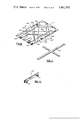
- FIG. 1 is a perspective view of the preferred embodiment of the present invention, showing some of the structural elements thereof in "exploded" array, including the basic outer support structure, the interior insertable frame supporting two, interchangeable complementary elements, an interchangeable principal playing element, and an associated ball receiving tray;
- FIG. 2 is a perspective view of the interior frame, with the two, interchangeable complementary elements being shown in "exploded" array, of the embodiment of FIG. 1;
- FIG. 3 is a perspective view of the fully assembled game of the preferred embodiment of the present invention with an accessory (a curved peripheral backboard) shown in "exploded" array;
- FIG. 4 is a cross-sectional view of the preferred embodiment, taken along section lines 4--4 of FIG. 3, with the accessory of FIG. 3 not included.
- FIGS. 5-12 are perspective views of the various elements, some in multiple embodiments, and accessories of the preferred embodiments of the educational and recreational game of the present invention, as outlined below:
- FIG. 5 - a first, basic embodiment of the interchangeable principal playing surface
- FIG. 6 - a second, advanced embodiment of the interchangeable principal playing surface (not heretofore illustrated);
- FIG. 7 - a first, exemplary embodiment of the complementary playing element
- FIG. 8 - a second, exemplary embodiment of the complementary playing element
- FIG. 9 - a third, exemplary, advanced embodiment (not heretofore illustrated) of the complementary playing element
- FIG. 10 - a shooter accessory for use in propelling the ball on the principal playing surface
- FIG. 11 an accessory strip for providing a "number line"
- FIG. 12 - a straight corner strip or backboard accessory.
- the preferred embodiment of the educational and recreational game apparatus of the present invention includes in its construction an outer generally rectangular support structure 1 and interior frame 2 with an interchangeable principal playing surface 3 and two underlying, complementary playing elements 4.
- the principal playing surface 3 may be for example either the basic version 30a illustrated (note also FIG. 5) or the advanced version 30b (FIG. 6).
- the first embodiment of the basic principal playing surface 30a illustrated in FIG. 5 has an arch-shaped cylindrical target 31a, which can be either removably or non-removably mounted atop its surface, and two circular openings 32a flush within the playing surface.
- Balls 100 which are hand launched, or alternatively mechanically launched by a suitable shooter (note FIG. 10), are to roll through the cylindrical openings 32a in order that points may be scored by the players.
- a spherical barrier 33a is placed atop the surface to prevent a player from rolling balls directly through the arch shaped cylindrical target 31a. Because of the barrier 33a more skill is required on the part of the players since the ball must first strike one of the side peripheral frame or structural support edges 11 in an angular direction. However, points may also be scored by rolling the ball in a straight line against the back frame 12 and into one of the circular openings 32a for fewer points.
- the second embodiment or advanced principal playing surface 30b illustrated in FIG. 6 has four arch-shaped cylindrical targets 31b on its surface and four circular openings 32b flush within the surface. Spherical barriers 33b are provided to add excitement and greater challenge to the playing action.
- Both positive and negative points can be assigned to certain openings disposed about the principal playing surface.
- the principal playing surfaces 3 are equipped with prongs 34a, 34b at the two upper corners. These prongs 34a, 34b plug into openings 21 on the corresponding corners of the interior frame 2. Such connection allows for the principal playing surfaces 3 to be firmly attached but still easily removed.
- inner frame structure 2 The interior sides of inner frame structure 2 are provided with grooves 22 which support the insertable and removable complementary elements 4 (note particularly FIGS. 2 and 4).
- the inner frame 2 in turn is inserted into the multipurpose outer frame or basic structure support 1.
- the basic support structure 1 has several functions. It provides: (a) an enclosure to contain the launched ball and against which the ball strikes, (b) a structure with inner grooves 16 parallel with its sides for holding the interior frame structure (note particularly FIGS. 1 and 4) and (c) a means to support the ball receiving and holding tray 5.
- the latter is removable and, because of its construction with wider side pieces and its location, serves to hold the underlying complementary surfaces 4 in their proper position.
- the removable tray 5 is fixed to the bottom end of the basic support structure 1 by means of male pins 13 which mate with female holes in the edges of the basic frame 1.
- Side ball receiving compartments 14 are provided in the tray 5 to extend pass both side edges of the basic frame 1 (note FIG. 3).
- the basic frame 1 has a "partial bottom" 15 (note FIG. 1) which extends under and leads to the removable ball receiving tray 5.
- the underlying complementary surfaces or elements 4 can be of many different forms, and, for purposes of illustration, three different embodiments will be described with particular reference to FIGS. 7, 8 and 9.
- the first embodiment 40a (note FIG. 7) has on its surface 41a two parallel strips 42a' 42a" of for example plastic or some other suitable material.
- the strips 42a', 42a" run perpendicualr to the back side 43a, one strip 42a' being aligned with elongated opening 44a' and the other 42a" with elongated openings 44a".
- Two right angles are thus formed between the lines 42a', 42a" and the backside 43a.
- a third strip (not illustrated) can be placed at the upper central section of the surface 41a along the back side 43a to positively illustrate the two right angles formed with the other two strips 42a', 42a".
- the first embodiment 40a of the underlying complementary surface 4 thus illustrates the characteristics of perpendicular or right angle figures and relationships.
- the second embodiment 40b (note FIG. 8) of the underlying complementary surface 4 also utilizes several strips of plastic or some other suitable material.
- Strip 42b' originates at elongated opening 44b' and intersects side 46b", thus forming two acute angles and one obtuse angle therewith. It then extends in an angular direction to the midpoint 43b' of back side 43b where two equal acute angles and one obtuse angle are formed.
- the strip then continues as line 42b" until it intersects side 46b' at a point directly opposite its intersection of side 46b" and an identical set of angles formed.
- the strip then terminates as line 42b" at elongated opening 44b" after having formed a diamondlike figure or quadrilaterial, forming two pairs of vertical angles, and several triangles.
- a second strip originates as line 42bb' from elongated opening 44b', and it intersects the left side 46b" where three angles are formed.
- the strip 42bb” then intersects side 43b and goes back to a point corresponding to where the opening of the central, arch-shaped target 31a is located on the principal playing surface 30a (note FIGS. 3 and 5).
- the strip as line 42bb" again intersect back side 43b at a point to the right of elongated opening 44b' and then it intersects side 46b', where again two acute and one obtuse angles are formed.
- Strip 42bb" then terminates at elongated opening 44b" which corresponds to the location of target opening 32a on the basic principal playing surface 30a.
- Strip 42bb', 42bb" thus forms among other figures, a parallelogram, several quadrilaterals, triangles and pairs of vertical angles.
- the third embodiment 40c (note FIG. 9) of the complementary element 4 is the corresponding insert for the advanced principal playing surface 30b (note FIG. 6) and has many complex geometric arrangements thereon.
- Strip 421 is parallel and nearest to side 46c". It is aligned in a manner to direct a player to roll the ball from the left-most circular opening 32b to a point in line with an arch-shaped target 31b atop the principal playing surface 30b.
- Strip 422 is similarly positioned as strip 421, yet on the opposite side of the complementary surface 41c, nearest side 46c'.
- the strips 421 and 422 connect the directional and formational lines 427 and 428 which originate at points slightly above the outer elongated openings 44c which correspond to the outer circular openings 32b.
- strips 424 and 426 intersect sides 46c' and 43c, while strips 425 and 427 intersects sides 46c" and 43c.
- Strips 421, 423, 425, and 427 terminate at points corresponding to the arch-shaped targets 31b on the advanced principal playing surface 30b.
- Strips 424, 426 and 428 are identically placed as their counterparts, strips 423, 425 and 427, except for being on the opposite side of the surface 41c.
- Strips 426 and 428 intersect sides 46c', 43c and 46c", while strip 424 intersects only sides 46c" and 43c.
- Strips 422, 424, 426 and 428 like strips 421, 423, 425 and 427, terminate at points corresponding to the arch-shaped cylindrical targets 31b atop the advanced principal playing surface 30b.
- the eight strips of the third embodiment 40c thus collectively form more than a hundred and fifty angles and many polygons including more than thirty triangles.
- exemplary "added-on" or accessory features are for example the curved strip 60 (note FIG. 3) and the straight strip 70 (note FIG. 12).
- These strips 60, 70 of plastic or some other suitable material can be positioned in the back end or corners, respectively, of the device and thereby relocate the action on the principal playing surface 3 by preventing the ball from striking the rectangular back corners of the frame edges 11, 12 but instead hitting the curve shaped strip 60 or the straight strip 70.
- Suction cups 61, 71 can be attached to the strips 60, 70, respectively for fastening the strips to the principal playing surface 3. Additional complementary elements having suitable strips thereon to properly indicate the new paths caused by the addition of the strips 60, 70 could be utilized.
- the present invention also allows for the inclusion of "puzzle pieces” corresponding to the actual size of each geometric figure represented on the complementary surfaces 4.
- the type of geometric figure and corresponding degrees of the respective angles can be labeled on each "puzzle piece.”
- One's ability to recognize angles, and other geometric figures will be greatly enhanced by this addition.
- FIG. 10 A suitable shooter accessory for mechanically propelling the ball 100 across the principal playing surface 3 is illustrated in FIG. 10.
- the shooter comprises a cylindrical barrel 80 having a ball receiving aperture 83 in its upper surface.
- Pull actuating handle which is biased inwardly by spring 81, can be used to strike the ball 100 with striking surface 84 in the well-known way.
- the game 1 sits on legs which are longer at the upper, top of the game so that the principal playing surface 3 and complementary elements 4 have a slight incline to them. Hence a ball rolling on these surfaces have a tendency to roll down the surface under the force of gravity. This action gives a slight bias to the roll and path of the ball as it traverses the surface, which becomes particularly effective when the ball begins to slow down and is traveling at an angle to the longitudinal axis of the surface.
- This bias adds a "ball disturbing" factor which further adds to the excitement and challenge to the game.
- the elongated, terminal slots 44a', 44a", 44b', 44b" in the complementary elements 4 line up with the circular holes or targets 32a of the principal playing element 3.
- This structure which is an important feature, allows the ball to drop through the target and the ball return, and yet allows the elements 3 and 4 to be placed close together in juxtaposition.
- multiple complementary surfaces 4 can be used as illustrated in FIGS. 1-3, or only one used as desired, enhancing the flexibility of the game. Additionally, rather than using legs 34a and placing the element 3 down into the game, a slot (analogous to slots 22) could likewise be provided for it.
- the interior frame 2 principal playing surfaces 3 and underlying complementary surfaces or elements 4 are formed from transparent plastic, such as "plexiglass,” or any other suitable material.
- the outer frame or structural support 1, spherical barriers, 33a, 33b, ball receiving tray 5 and archshaped cylindrical targets 31a, 31b, can also be formed from plastic, such as "plexiglass” (preferably colored), or some other suitable material.
Landscapes
- Engineering & Computer Science (AREA)
- Multimedia (AREA)
- Educational Technology (AREA)
- Toys (AREA)
Abstract
An educational and recreational game having a case-like rectangular basic structure including an outer support structure and an interior frame with interchangeable principal transparent playing elements and insertable underlying complementary transparent elements which upon insertion change the style of recreational play and introduce various mathematical relationships represented by lines on the elements into the game. The complementary elements or inserts singularly and collectively form a series of mathematical figures which are used in basic and advanced mathematics and are used in the game for instructional purposes. There are several circular openings in the principal playing surfaces with associated arch-shaped, cylindrical targets and stops located atop the principal playing surfaces. Structure is provided for retrieving the balls which roll upon the principal playing surface. In use, balls are manually propelled across the principal playing surface, and, ideally, after striking a peripheral, multi-purpose frame or structural support, roll into one of the circular openings if the ball was propelled along the lines on the complementary elements. Points, line segments, various types of angles, triangles, hexagons, parallelograms, and other polygons are some of the mathematical representations utilized in the game.
Description
This invention relates in general to educational and recreational games in which balls are rolled into openings disposed about a flat playing surface and more specifically to the structure of the game and its method of use for certain recreational and/or educational ends.
It is of course well known in the prior art to have games which utilize balls propelled by means of a shooter mechanism over a playing surface, the balls being dropped through holes or passed through channels to score certain points, and these types of games have generally been called pin ball games. The present invention is directed to a new form of this type of game which can be utilized for recreational and educational purposes.
The educational and recreational game apparatus of the present invention includes inter alia a rectangular, outer structure which supports a main or principal playing surface element at an upper level while one or more underlying complementary elements are removably located at lower levels. To the inventor's knowledge no other game of a comparative nature has been so constructed as the present invention which utilizes the above generally described structure and which further includes a unique series of geometric figures which are readily adaptable and extraordinarily appropriate for the teaching of basic and advanced mathematics.
Additionally, the present invention can more than adequately provide genuine entertainment for all members of the family. The educational and recreational utility of this invention extends to persons of all ages, including those whose prior mathematical background may be minimal.
For a further understanding of the nature and objects of the present invention, reference should be had to the following detailed description, taken in conjunction with the accompanying drawings, in which like parts are given like reference numerals and wherein:
FIG. 1 is a perspective view of the preferred embodiment of the present invention, showing some of the structural elements thereof in "exploded" array, including the basic outer support structure, the interior insertable frame supporting two, interchangeable complementary elements, an interchangeable principal playing element, and an associated ball receiving tray;
FIG. 2 is a perspective view of the interior frame, with the two, interchangeable complementary elements being shown in "exploded" array, of the embodiment of FIG. 1;
FIG. 3 is a perspective view of the fully assembled game of the preferred embodiment of the present invention with an accessory (a curved peripheral backboard) shown in "exploded" array;
FIG. 4 is a cross-sectional view of the preferred embodiment, taken along section lines 4--4 of FIG. 3, with the accessory of FIG. 3 not included.
All of the other figures, FIGS. 5-12, are perspective views of the various elements, some in multiple embodiments, and accessories of the preferred embodiments of the educational and recreational game of the present invention, as outlined below:
FIG. 5 - a first, basic embodiment of the interchangeable principal playing surface;
FIG. 6 - a second, advanced embodiment of the interchangeable principal playing surface (not heretofore illustrated);
FIG. 7 - a first, exemplary embodiment of the complementary playing element;
FIG. 8 - a second, exemplary embodiment of the complementary playing element;
FIG. 9 - a third, exemplary, advanced embodiment (not heretofore illustrated) of the complementary playing element;
FIG. 10 - a shooter accessory for use in propelling the ball on the principal playing surface;
FIG. 11 - an accessory strip for providing a "number line" and
FIG. 12 - a straight corner strip or backboard accessory.
As illustrated particularly in FIGS. 1-4, the preferred embodiment of the educational and recreational game apparatus of the present invention includes in its construction an outer generally rectangular support structure 1 and interior frame 2 with an interchangeable principal playing surface 3 and two underlying, complementary playing elements 4.
The principal playing surface 3 may be for example either the basic version 30a illustrated (note also FIG. 5) or the advanced version 30b (FIG. 6).
The first embodiment of the basic principal playing surface 30a illustrated in FIG. 5 has an arch-shaped cylindrical target 31a, which can be either removably or non-removably mounted atop its surface, and two circular openings 32a flush within the playing surface. Balls 100 which are hand launched, or alternatively mechanically launched by a suitable shooter (note FIG. 10), are to roll through the cylindrical openings 32a in order that points may be scored by the players.
A spherical barrier 33a is placed atop the surface to prevent a player from rolling balls directly through the arch shaped cylindrical target 31a. Because of the barrier 33a more skill is required on the part of the players since the ball must first strike one of the side peripheral frame or structural support edges 11 in an angular direction. However, points may also be scored by rolling the ball in a straight line against the back frame 12 and into one of the circular openings 32a for fewer points.
The second embodiment or advanced principal playing surface 30b illustrated in FIG. 6 has four arch-shaped cylindrical targets 31b on its surface and four circular openings 32b flush within the surface. Spherical barriers 33b are provided to add excitement and greater challenge to the playing action.
Both positive and negative points can be assigned to certain openings disposed about the principal playing surface.
The principal playing surfaces 3 are equipped with prongs 34a, 34b at the two upper corners. These prongs 34a, 34b plug into openings 21 on the corresponding corners of the interior frame 2. Such connection allows for the principal playing surfaces 3 to be firmly attached but still easily removed.
The interior sides of inner frame structure 2 are provided with grooves 22 which support the insertable and removable complementary elements 4 (note particularly FIGS. 2 and 4). The inner frame 2 in turn is inserted into the multipurpose outer frame or basic structure support 1.
The basic support structure 1 has several functions. It provides: (a) an enclosure to contain the launched ball and against which the ball strikes, (b) a structure with inner grooves 16 parallel with its sides for holding the interior frame structure (note particularly FIGS. 1 and 4) and (c) a means to support the ball receiving and holding tray 5. The latter is removable and, because of its construction with wider side pieces and its location, serves to hold the underlying complementary surfaces 4 in their proper position. The removable tray 5 is fixed to the bottom end of the basic support structure 1 by means of male pins 13 which mate with female holes in the edges of the basic frame 1. Side ball receiving compartments 14 are provided in the tray 5 to extend pass both side edges of the basic frame 1 (note FIG. 3). The basic frame 1 has a "partial bottom" 15 (note FIG. 1) which extends under and leads to the removable ball receiving tray 5.
The underlying complementary surfaces or elements 4 can be of many different forms, and, for purposes of illustration, three different embodiments will be described with particular reference to FIGS. 7, 8 and 9.
The first embodiment 40a (note FIG. 7) has on its surface 41a two parallel strips 42a' 42a" of for example plastic or some other suitable material. The strips 42a', 42a" run perpendicualr to the back side 43a, one strip 42a' being aligned with elongated opening 44a' and the other 42a" with elongated openings 44a". Two right angles are thus formed between the lines 42a', 42a" and the backside 43a. A third strip (not illustrated) can be placed at the upper central section of the surface 41a along the back side 43a to positively illustrate the two right angles formed with the other two strips 42a', 42a". The first embodiment 40a of the underlying complementary surface 4 thus illustrates the characteristics of perpendicular or right angle figures and relationships.
The second embodiment 40b (note FIG. 8) of the underlying complementary surface 4 also utilizes several strips of plastic or some other suitable material. Strip 42b' originates at elongated opening 44b' and intersects side 46b", thus forming two acute angles and one obtuse angle therewith. It then extends in an angular direction to the midpoint 43b' of back side 43b where two equal acute angles and one obtuse angle are formed. The strip then continues as line 42b" until it intersects side 46b' at a point directly opposite its intersection of side 46b" and an identical set of angles formed. The strip then terminates as line 42b" at elongated opening 44b" after having formed a diamondlike figure or quadrilaterial, forming two pairs of vertical angles, and several triangles. A second strip originates as line 42bb' from elongated opening 44b', and it intersects the left side 46b" where three angles are formed. The strip 42bb" then intersects side 43b and goes back to a point corresponding to where the opening of the central, arch-shaped target 31a is located on the principal playing surface 30a (note FIGS. 3 and 5). The strip as line 42bb" again intersect back side 43b at a point to the right of elongated opening 44b' and then it intersects side 46b', where again two acute and one obtuse angles are formed. The strip 42bb" then terminates at elongated opening 44b" which corresponds to the location of target opening 32a on the basic principal playing surface 30a. Strip 42bb', 42bb" thus forms among other figures, a parallelogram, several quadrilaterals, triangles and pairs of vertical angles.
The third embodiment 40c (note FIG. 9) of the complementary element 4 is the corresponding insert for the advanced principal playing surface 30b (note FIG. 6) and has many complex geometric arrangements thereon. Strip 421 is parallel and nearest to side 46c". It is aligned in a manner to direct a player to roll the ball from the left-most circular opening 32b to a point in line with an arch-shaped target 31b atop the principal playing surface 30b. Strip 422 is similarly positioned as strip 421, yet on the opposite side of the complementary surface 41c, nearest side 46c'. The strips 421 and 422 connect the directional and formational lines 427 and 428 which originate at points slightly above the outer elongated openings 44c which correspond to the outer circular openings 32b. The strips are placed in an angular direction so that the strips 424 and 426 intersect sides 46c' and 43c, while strips 425 and 427 intersects sides 46c" and 43c. Strips 421, 423, 425, and 427 terminate at points corresponding to the arch-shaped targets 31b on the advanced principal playing surface 30b. Strips 424, 426 and 428 are identically placed as their counterparts, strips 423, 425 and 427, except for being on the opposite side of the surface 41c. Strips 426 and 428 intersect sides 46c', 43c and 46c", while strip 424 intersects only sides 46c" and 43c. Strips 422, 424, 426 and 428 like strips 421, 423, 425 and 427, terminate at points corresponding to the arch-shaped cylindrical targets 31b atop the advanced principal playing surface 30b. The eight strips of the third embodiment 40c thus collectively form more than a hundred and fifty angles and many polygons including more than thirty triangles.
Given the various mathematical relationships inherent in the above described, three embodiments of the complementary elements 4, both general and specific mathematical concepts can be highlighted which are suitable for instructional purposes. Listed below are but a few of the many such features obtainable in the preferred embodiments of the present invention which are illustrative of its general versatility: (1) points, (2) line segments, (3) parallel lines, (4) perpendicular lines, (5) angles, in general, (6) acute angles, (7) equal angles, (8) obutse angles, (9) vertical or right angles, (10) adjacent angles, (11) triangles, and (12) other polygons.
For purposes of added clarification, samples of the guide lines on the complementary elements 4 have been indicated by phantom lines on the principal playing surface 3 in FIGS. 5 and 6 to indicate the location of where they would appear when viewed through the transparent playing surface 3. In particular guide lines 42b', 42b", 42bb', and 42bb" have been phantomed lined on playing surface 30a of FIG. 5, and guide lines 421, 424, 426 and 428 on playing surface 30b of FIG. 6.
In adding points as part of the recreational play, one gets practice computing both positive and negative numbers. For example, where a player first scores twenty points in a target on the third embodiment 40c of the complementary element 4 and should the same ball roll into a circular opening assigned for example ten points, the actual score for that particular launched ball would be "ten." To make the scoring process more easily understood by the younger players or students an "added-on" line accessory 50 (note FIG. 11) can be utilized. Subtraction, division, multiplication and addition can be performed using the number line 50. Furthermore, one can become more knowledgable about graphing points on a plane when the number line 50 is for example printed or included on one of the complementary inserts 4.
Some of the other possible embodiments of exemplary "added-on" or accessory features are for example the curved strip 60 (note FIG. 3) and the straight strip 70 (note FIG. 12). These strips 60, 70 of plastic or some other suitable material can be positioned in the back end or corners, respectively, of the device and thereby relocate the action on the principal playing surface 3 by preventing the ball from striking the rectangular back corners of the frame edges 11, 12 but instead hitting the curve shaped strip 60 or the straight strip 70. Suction cups 61, 71 can be attached to the strips 60, 70, respectively for fastening the strips to the principal playing surface 3. Additional complementary elements having suitable strips thereon to properly indicate the new paths caused by the addition of the strips 60, 70 could be utilized.
For additional educational and recreational purposes, the present invention also allows for the inclusion of "puzzle pieces" corresponding to the actual size of each geometric figure represented on the complementary surfaces 4. The type of geometric figure and corresponding degrees of the respective angles can be labeled on each "puzzle piece." One's ability to recognize angles, and other geometric figures will be greatly enhanced by this addition. These aspect of the present invention will afford one the use of protractors and other such mathematics paraphernalia to measure and compare angles.
A suitable shooter accessory for mechanically propelling the ball 100 across the principal playing surface 3 is illustrated in FIG. 10. The shooter comprises a cylindrical barrel 80 having a ball receiving aperture 83 in its upper surface. Pull actuating handle, which is biased inwardly by spring 81, can be used to strike the ball 100 with striking surface 84 in the well-known way.
The game 1 sits on legs which are longer at the upper, top of the game so that the principal playing surface 3 and complementary elements 4 have a slight incline to them. Hence a ball rolling on these surfaces have a tendency to roll down the surface under the force of gravity. This action gives a slight bias to the roll and path of the ball as it traverses the surface, which becomes particularly effective when the ball begins to slow down and is traveling at an angle to the longitudinal axis of the surface. Hence, in order for a player to hit a target, not only is the direction of propulsion of the ball important, but often also the force of propulsion, the ball sometimes being "dropped" into the target. This bias adds a "ball disturbing" factor which further adds to the excitement and challenge to the game.
As shown in FIG. 3, the elongated, terminal slots 44a', 44a", 44b', 44b" in the complementary elements 4 line up with the circular holes or targets 32a of the principal playing element 3. This structure, which is an important feature, allows the ball to drop through the target and the ball return, and yet allows the elements 3 and 4 to be placed close together in juxtaposition.
It is noted that multiple complementary surfaces 4 can be used as illustrated in FIGS. 1-3, or only one used as desired, enhancing the flexibility of the game. Additionally, rather than using legs 34a and placing the element 3 down into the game, a slot (analogous to slots 22) could likewise be provided for it.
Preferably the interior frame 2, principal playing surfaces 3 and underlying complementary surfaces or elements 4 are formed from transparent plastic, such as "plexiglass," or any other suitable material. The outer frame or structural support 1, spherical barriers, 33a, 33b, ball receiving tray 5 and archshaped cylindrical targets 31a, 31b, can also be formed from plastic, such as "plexiglass" (preferably colored), or some other suitable material.
Because many varying and different embodiments may be made within the scope of the inventive concept herein taught, and because many modifications may be made in the embodiments herein detailed in accordance with the descriptive requirements of the law, it is to be understood that the details herein are to be interpreted as illustrative and not in a limiting sense.
Claims (9)
1. An educational and recreational game comprising:
a basic support frame;
at least one principal playing surface element of transparent material mounted on said support frame having targets mounted thereon and on which balls are rolled at said targets;
a multiple number of interchangeable complementary playing elements, each having different sets of path lines disposed thereon associated with said principal playing surface element; each set of path lines on said complementary elements being keyed to said targets and used to show the path which the ball should travel on said principal playing surface element to hit said targets and designed to illustrate certain geometrical relationships and/or figures;
said complementary playing elements being made of transparent material, at least two of them being usable in said game at the same time, the complementary playing elements being located when in use beneath said principal playing surface element, said path lines of each of said complementary playing elements when in use being visible through said transparent material of said principal playing surface element and any of said complementary playing surface elements positioned thereabove.
2. The game of claim 1 wherein said at least one of said targets comprises a hole in said principal playing surface, the ball when hitting said target dropping through said hole down into said upper one of said complementary surfaces, at least the upper one of said complementary surfaces having an aperture therein through which the ball can further drop.
3. The game of claim 1 wherein there is included a multiple number of interchangeable principal playing surfaces, each having different sets of targets mounted thereon, each set designed to illustrate in conjunction with one or more of said complementary playing elements certain geometrical relationships and/or figures.
4. The game of claim 1 wherein said support frame is basically rectangular in shape and wherein there is further included peripheral sides extending up along three edges of said principal playing surface element forming side and back-stops against which the balls are rolled.
5. The game of claim 4 wherein said support frame has at least one set of ledges along at least two of its opposing inner sides upon which said complementary playing elements are supported, the fourth side of said frame being removable to expose at least the fourth edge of said complementary elements for easy removal and changing thereof.
6. The game of claim 5 wherein the removable fourth side comprises a removable wall which also serves as a ball receiving and holding tray.
7. The game of claim 1 wherein there is further included an accessory item comprising a back-stop strip which can be placed on said principal playing surface element blocking at least a portion of said peripheral sides changing the paths which a ball will take when rolled across said principal playing surface element.
8. The game of claim 7 where said strip is curved.
9. The game of claim 7 wherein said strip is straight.
Priority Applications (1)
| Application Number | Priority Date | Filing Date | Title |
|---|---|---|---|
| US05/438,019 US3961793A (en) | 1974-01-30 | 1974-01-30 | Educational and recreational game |
Applications Claiming Priority (1)
| Application Number | Priority Date | Filing Date | Title |
|---|---|---|---|
| US05/438,019 US3961793A (en) | 1974-01-30 | 1974-01-30 | Educational and recreational game |
Publications (1)
| Publication Number | Publication Date |
|---|---|
| US3961793A true US3961793A (en) | 1976-06-08 |
Family
ID=23738874
Family Applications (1)
| Application Number | Title | Priority Date | Filing Date |
|---|---|---|---|
| US05/438,019 Expired - Lifetime US3961793A (en) | 1974-01-30 | 1974-01-30 | Educational and recreational game |
Country Status (1)
| Country | Link |
|---|---|
| US (1) | US3961793A (en) |
Cited By (7)
| Publication number | Priority date | Publication date | Assignee | Title |
|---|---|---|---|---|
| US4198047A (en) * | 1978-08-07 | 1980-04-15 | Anjar, Inc. | Multi compartment game board |
| US4239219A (en) * | 1979-03-26 | 1980-12-16 | Haefliger Robert W | Pinball apparatus with replaceable modular barrier supports |
| US4555235A (en) * | 1982-09-29 | 1985-11-26 | Burroughs Robert C | Return top |
| FR2630337A1 (en) * | 1988-04-26 | 1989-10-27 | Lantz Marcel | Table golf |
| US4909517A (en) * | 1988-12-23 | 1990-03-20 | Furlong Donald F | Rolling ball game |
| US5669611A (en) * | 1996-07-30 | 1997-09-23 | Fedele; Stephen | Mathematical game apparatus |
| US6729964B2 (en) | 2002-06-12 | 2004-05-04 | Charles E. Reeves, Jr. | Billiards practice table |
Citations (8)
| Publication number | Priority date | Publication date | Assignee | Title |
|---|---|---|---|---|
| US207835A (en) * | 1878-09-10 | Improvement in game-tables | ||
| US683566A (en) * | 1901-02-11 | 1901-10-01 | Henry Meyers | Game-table. |
| GB320404A (en) * | 1928-07-12 | 1929-10-14 | Arthur William Gawler | Appliances for playing an indoor game |
| US1971295A (en) * | 1933-04-10 | 1934-08-21 | Calaluca Leonardo | Game apparatus |
| DK106313C (en) * | 1963-09-25 | 1967-01-16 | Aage Buron | Billiards table with separate frame. |
| US3743288A (en) * | 1972-06-16 | 1973-07-03 | L Danklefsen | Combination pool table and billiard balls including erratic movement and shot directing features |
| US3825258A (en) * | 1972-03-17 | 1974-07-23 | E Frierman | Floor type billiard game with compensating pocket density arrangement |
| US3829097A (en) * | 1972-07-05 | 1974-08-13 | A Rohrmuller | Ball type game |
-
1974
- 1974-01-30 US US05/438,019 patent/US3961793A/en not_active Expired - Lifetime
Patent Citations (8)
| Publication number | Priority date | Publication date | Assignee | Title |
|---|---|---|---|---|
| US207835A (en) * | 1878-09-10 | Improvement in game-tables | ||
| US683566A (en) * | 1901-02-11 | 1901-10-01 | Henry Meyers | Game-table. |
| GB320404A (en) * | 1928-07-12 | 1929-10-14 | Arthur William Gawler | Appliances for playing an indoor game |
| US1971295A (en) * | 1933-04-10 | 1934-08-21 | Calaluca Leonardo | Game apparatus |
| DK106313C (en) * | 1963-09-25 | 1967-01-16 | Aage Buron | Billiards table with separate frame. |
| US3825258A (en) * | 1972-03-17 | 1974-07-23 | E Frierman | Floor type billiard game with compensating pocket density arrangement |
| US3743288A (en) * | 1972-06-16 | 1973-07-03 | L Danklefsen | Combination pool table and billiard balls including erratic movement and shot directing features |
| US3829097A (en) * | 1972-07-05 | 1974-08-13 | A Rohrmuller | Ball type game |
Non-Patent Citations (1)
| Title |
|---|
| Billiards for Everyone by Luther Lassiter and George Sullivan, Grosset and Dunlap, Feb., 1972, p. 49. * |
Cited By (7)
| Publication number | Priority date | Publication date | Assignee | Title |
|---|---|---|---|---|
| US4198047A (en) * | 1978-08-07 | 1980-04-15 | Anjar, Inc. | Multi compartment game board |
| US4239219A (en) * | 1979-03-26 | 1980-12-16 | Haefliger Robert W | Pinball apparatus with replaceable modular barrier supports |
| US4555235A (en) * | 1982-09-29 | 1985-11-26 | Burroughs Robert C | Return top |
| FR2630337A1 (en) * | 1988-04-26 | 1989-10-27 | Lantz Marcel | Table golf |
| US4909517A (en) * | 1988-12-23 | 1990-03-20 | Furlong Donald F | Rolling ball game |
| US5669611A (en) * | 1996-07-30 | 1997-09-23 | Fedele; Stephen | Mathematical game apparatus |
| US6729964B2 (en) | 2002-06-12 | 2004-05-04 | Charles E. Reeves, Jr. | Billiards practice table |
Similar Documents
| Publication | Publication Date | Title |
|---|---|---|
| US4012042A (en) | Invertible pocketed target for a disc throwing game | |
| US3514110A (en) | Board game apparatus with playing pieces,tokens and markers | |
| US4277067A (en) | Game device with board surfaces visible only to opposing players | |
| US3464701A (en) | Game apparatus for playing threedimensional chess and tic-tac-toe | |
| US4163559A (en) | Compartmented card game box with removable drawer | |
| US3582075A (en) | Word game including catapult means and indicia-displaying projectiles | |
| US3504914A (en) | Combined target,disk markers,and ball game | |
| US3899173A (en) | Simulated basketball game | |
| US4359227A (en) | Game of chance | |
| US3623729A (en) | Three-dimensional board game apparatus | |
| US3924859A (en) | Arithmetic fact game | |
| US3503612A (en) | Word forming game apparatus | |
| US20230122635A1 (en) | Card toss game and gameplay method | |
| US4022473A (en) | Apparatus for playing matching game | |
| US3961793A (en) | Educational and recreational game | |
| US5100141A (en) | Dice scrambler | |
| US4989879A (en) | Football board game | |
| US4163560A (en) | Board game | |
| US4643433A (en) | Target game | |
| US5927718A (en) | Game apparatus | |
| US4927158A (en) | Game | |
| US4188036A (en) | Board game with letter shaped playing pieces | |
| US3351344A (en) | Target assembly with removable target chutes of varying height | |
| US3073601A (en) | Game apparatus | |
| US4550911A (en) | Scoot ball game apparatus |