US404457A - Railway-signal - Google Patents
Railway-signal Download PDFInfo
- Publication number
- US404457A US404457A US404457DA US404457A US 404457 A US404457 A US 404457A US 404457D A US404457D A US 404457DA US 404457 A US404457 A US 404457A
- Authority
- US
- United States
- Prior art keywords
- wires
- rod
- negative
- positive
- springs
- Prior art date
- Legal status (The legal status is an assumption and is not a legal conclusion. Google has not performed a legal analysis and makes no representation as to the accuracy of the status listed.)
- Expired - Lifetime
Links
- 230000000994 depressogenic effect Effects 0.000 description 5
- 239000011810 insulating material Substances 0.000 description 4
- 239000011521 glass Substances 0.000 description 3
- RYGMFSIKBFXOCR-UHFFFAOYSA-N Copper Chemical compound [Cu] RYGMFSIKBFXOCR-UHFFFAOYSA-N 0.000 description 2
- 229910052802 copper Inorganic materials 0.000 description 2
- 239000010949 copper Substances 0.000 description 2
- 230000000694 effects Effects 0.000 description 2
- 101100400378 Mus musculus Marveld2 gene Proteins 0.000 description 1
- 229940000425 combination drug Drugs 0.000 description 1
- 238000010276 construction Methods 0.000 description 1
- 230000000881 depressing effect Effects 0.000 description 1
- LTMHDMANZUZIPE-PUGKRICDSA-N digoxin Chemical compound C1[C@H](O)[C@H](O)[C@@H](C)O[C@H]1O[C@@H]1[C@@H](C)O[C@@H](O[C@@H]2[C@H](O[C@@H](O[C@@H]3C[C@@H]4[C@]([C@@H]5[C@H]([C@]6(CC[C@@H]([C@@]6(C)[C@H](O)C5)C=5COC(=O)C=5)O)CC4)(C)CC3)C[C@@H]2O)C)C[C@@H]1O LTMHDMANZUZIPE-PUGKRICDSA-N 0.000 description 1
- 239000012212 insulator Substances 0.000 description 1
- 229920000136 polysorbate Polymers 0.000 description 1
- 238000005096 rolling process Methods 0.000 description 1
- 238000000926 separation method Methods 0.000 description 1
- 230000002459 sustained effect Effects 0.000 description 1
Images


Classifications
-
- A—HUMAN NECESSITIES
- A63—SPORTS; GAMES; AMUSEMENTS
- A63H—TOYS, e.g. TOPS, DOLLS, HOOPS OR BUILDING BLOCKS
- A63H19/00—Model railways
- A63H19/34—Bridges; Stations; Signalling systems
Definitions
- FIG. 1 A first figure.
- Figure 1 represents a por- .electric wires attached to contact-springs D D, one g of which wires passes to the negative main B, (see Fig. 2,) and all of the other tion of a track supplied with my electric signals;
- Fig. 2 a cross-sectional view of the same, showing the springs for carrying the circuitmaking rod;
- Fig. 3 an elevation of a broken section of track, showing an electric switchblock;
- Fig. 4 a detached plan View of an electric switch-block.
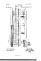
- Fig. 5 is a plan View of a double-track road with my invention applied thereto, showing particularly my system of electric wires connecting with the signals on one side of the track;
- Fig. 6, a plan view of a double-track road;
- Fig. 7 a similar View of a single-track road
- Fig. 8 a perspective View of a double-track road provided with my signal.
- Fig. 9 represents a section of a lamp post or pole
- Fig. 10 a view of road with station, but no siding
- Fig. 11 a lamp with supporting-post.
- Fig. 12 is a detached view, showing in elevation my roller;depressor arranged inside the wheel to operate the negative contact mechanism by rolling over the inside rod without pushing it longitudinally.
- Fig. 13 is a detached partial or broken view of sections 5, 6, 7, and 8 of the wires carrying electric lights h h h", the arrangement of the wires being shown more in detail in Fig. 5.
- Fig. 14 is a detached broken view designed to illustrate the connection of main wires B and B with a Brush electric-light machine.
- a A are the two rails.
- B is the positive, and B the negative, elec tric mains set between the rails; O, a flat rod set within one of the rails A and parallel therewith slightlybelow the level of the upper surface of the rail. It is sustained by springs C 0 set at intervals upon the ties C", and is on the upper face of switch-block E.
- D D D D D are seven small contact-springs set on an insulating material D (see Fig. 3) v
- a copper plate 0" on the under face of rod 0, separated therefrom by the insulating material, is so set that when the said rod is depressed contact between springs D D D is made by plate 0 touching all the springs D D simultaneously.
- the circuit is broken by the rebound of springs C, which raise the rod when the pressure of the wheels is removed.
- a, b, 0, cl, 6, f, and 9 are seven six connect with six corresponding wires a b c d e f in long box or conduit F.
- the box F is parallel with and outside of the rails A A, and the wires a 1) 0d 6 f are carried to it under that rail A intervening between blocks E and the box F. All these wires are covered with insulating material.
- the wires in box F areconnected with signal-lamps, each wire passing from the positive. electric main B to a lamp and thence back to negative main B. fWVhen the rod A is depressed, it touches all of the contactspringsD D D of each series :beneath it simultaneously.
- a train or engine with its tender is never less than forty-one feet in length, and the switch-blocks E are 5 placed about forty feet apart.
- the flanges of the wheels or (in case they are used) rollers I will thus bear down upon rod 0 over one or more of switch-blocks E at all times.
- a short metallic (say copper) strip 0 on the bottom of the rod 0, over each switch-block E,-is a short metallic (say copper) strip 0", (see Figs. 2 and 3,) with an insulating material between it and the rod.
- this strip 0 touches each contactspring D D D of the switch-block beneath it and brings them intoelectrical contact each with the others.
- a circuit is thus completed between the wires a b c d of, through wire g, with the negative main B.
- the circuit is made and broken at each switch-block E by hrowing plate or strip 0 into and out of contact with the contact-springs.
- Each wire ICO Q Q, Q Q (2)", &c. leadsfrom the positive main 1 to the half-mile of light wires in its own half-mile section and in the two half-mile sections ahead of it.
- the wire Q connects with light-wires a l) c in section 2, and wire a passes forward and down into section 4 through the cluster of wires lettered a".
- Vire b similarly passes forward into section to connect with the contactsprings of cluster of wires a, and wire 0 passes directly down into the same half-mile section in which Q, islocated to connect with the contact-springs of cluster a".
- Positive wire 'Q similarly connects with its own and two forward half-mile sections of lightwires. In this way the wires lettered Q (with its powers) keep the light-wires charged ready to ignite the carbons when circuit is made with wire g, which connects with the negative wire B.
- the system already described is set on each side of the track, the device being arranged to throw signals for trains moving to the right in the same manner as is already described, but for trains moving to the left a separate system arranged for the lower side of the track, (as shown in the drawings,) and the arrangement or operation is to throw white lights ahead of the train moving to the left, the red in its own half-section and the blue and white in the respective half-sections behind, so that trains running in opposite directions will opcrate them, as above described. In such case the flanges of the wheels will operate both.
- Fig. 11 I show one of my lights composed of three lamps inclosed in a glass casing.
- the latter maybe of any colored glass desired.
- the casing around the lamps may be made transparent in both sides forward and backward in the line of track and opaque on the two sides toward and opposite to the track, whereby the illui'nination of the interior may be perceptible through the glass in the daytime as well. as at night.
- the diameter is greater between the opposite edges of each flange than between those of the tread portion of the wheel.
- the wheel runs upon the tread, and the circumference of the flan ge being free travels faster than that of the tread. The flange will therefore tend to thrust the rod 0 backward as the train moves and to grind upon it.
- the springs 0 should be simply strong enough to sustain the rod without givin it very strong pressure against the flanges; otherwise the rod would be torn from its fastenings.
- a series of wheels or friction-rollers similar to I", Fig. 12 maybe rigged beneath ⁇ Vhether the the engine and each car so as to be in con stant contact with a rod 0 and roll freely and easily over it, their action being simply to depress rod 0 without friction, as the roller or wheel 1 turns loosely on its pin or axis, and only then when in contact with rod 0.
- the flanges, wheels, or rollers are intended to act as depressors to bear upon rod 0.
- This roller 1 is rigged beneath the cars between the rails immediately-inside the line of wheels, (see Fig. 12,) by means of frame I".
- the rod 0 is set so as to come in contact with it and far enough from the rail to avoid contact with the flanges of the'wheels. This is done when it is desired to avoid the back-thrust of the flanges. It is desired that the action upon rod 0 be merely a depressing action, or as nearly exclusively so as possible.
- the positive and negative mains B and B are simply two main lines connected with a dynamo or system of dynamos, which supply them with the electric current.
- Fig. 13 simply shows signal-lamps on sections of wires 5, 6, 7, and 8, the parts in Fig. 5 being too small for this purpose.
- Fig. 6 indicates that the signals may be set on each side of a double-track road
- Fig. 8 is a perspective View showing that they may be set on each side of a single track.
- Fig. 14 is designed to illustrate the connection of the positive and negative main wires B and B with a Brush electric-light machine, onlya part of the latter being shown, as I make no claim to it.
- the wire B joins coil IV and the current connects with wire B through this coil W, armature X, coil WV, through the commutator Y to positive main wire B.
- yVhat I claim as new is 1.
- connecting-wires g and a depressor attached ALBERT ⁇ VISNER.
Landscapes
- Train Traffic Observation, Control, And Security (AREA)
Description
(No Model.) 4 Sheets-Sheet 1. A. J. WISNER. RAILWAY SIGNAL.
N Patented June 4, 1889..
m. nuhwti viii-II;
witnesses.
WMZ v N. PETERS Phowlilhugraphen Washlllglnn. u. c.
(No Model.)
7 4 Sheets-Sheet 3. A. J. WISNER.
RAILWAY SIGNAL.
No. 404,457 Patented June 4, 1889.
FIG,
Uhih.
hiir.
white White 3 Quinn White.
{ma 8. whim LlueQtdkih 23 13 2} whit;
Ibl wa 'b'ue Tedawmh witnesses M WW7 N. PETERS, PhomLilhographar. Walhingian. II D 4 e e h S w e e h S 4 M N w ms Y m J L -M R M d o M 0 W No. 404,457. Patented June 4, 1889.
INVENTOlI mm,
WITNESSES:
UNITED STATES I PATENT OFFICE.
A. JACKSON WISNER, OF PHILADELPHIA, PENNSYLVANIA.
RAILWAY-SIGNAL.
SPECIFICATION forming part of Letters Patent No. 404,457, dated June 4, 1889.
' 7 Application filed January 24, 1888- Serial No. 261,709. (NomodeL) To all whom it Hwy-concern.-
Be it known that I, A. JACKSON WIsNER, a citizen of the United States, and a resident of Philadelphia, Pennsylvania, have invented a new and Improved System of Automatic Electric Railroad-Signals, of which the following is a full, clear, and exact description, reference being had to the annexed drawings, making part hereof.
The nature of my invention will fully appear from the following specification and claims. Its object is to prevent collision and other accidents to moving trains on railroads.
In the drawings, Figure 1 represents a por- .electric wires attached to contact-springs D D, one g of which wires passes to the negative main B, (see Fig. 2,) and all of the other tion of a track supplied with my electric signals; Fig. 2, a cross-sectional view of the same, showing the springs for carrying the circuitmaking rod; Fig. 3, an elevation of a broken section of track, showing an electric switchblock; Fig. 4, a detached plan View of an electric switch-block. Fig. 5 is a plan View of a double-track road with my invention applied thereto, showing particularly my system of electric wires connecting with the signals on one side of the track; Fig. 6, a plan view of a double-track road; Fig. 7, a similar View of a single-track road; Fig. 8, a perspective View of a double-track road provided with my signal.- Fig. 9 represents a section of a lamp post or pole; Fig. 10, a view of road with station, but no siding; Fig. 11 a lamp with supporting-post. Fig. 12 is a detached view, showing in elevation my roller;depressor arranged inside the wheel to operate the negative contact mechanism by rolling over the inside rod without pushing it longitudinally. Fig. 13 is a detached partial or broken view of sections 5, 6, 7, and 8 of the wires carrying electric lights h h h", the arrangement of the wires being shown more in detail in Fig. 5. Fig. 14 is a detached broken view designed to illustrate the connection of main wires B and B with a Brush electric-light machine.
A A are the two rails.
B is the positive, and B the negative, elec tric mains set between the rails; O, a flat rod set within one of the rails A and parallel therewith slightlybelow the level of the upper surface of the rail. It is sustained by springs C 0 set at intervals upon the ties C", and is on the upper face of switch-block E.
adapted to be depressed by the flangespf the wheels of a passing train.
D D D D are seven small contact-springs set on an insulating material D (see Fig. 3) v A copper plate 0" on the under face of rod 0, separated therefrom by the insulating material, is so set that when the said rod is depressed contact between springs D D D is made by plate 0 touching all the springs D D simultaneously. The circuit is broken by the rebound of springs C, which raise the rod when the pressure of the wheels is removed.
a, b, 0, cl, 6, f, and 9 (see Fig. 4) are seven six connect with six corresponding wires a b c d e f in long box or conduit F. The box F is parallel with and outside of the rails A A, and the wires a 1) 0d 6 f are carried to it under that rail A intervening between blocks E and the box F. All these wires are covered with insulating material. The wires in box F areconnected with signal-lamps, each wire passing from the positive. electric main B to a lamp and thence back to negative main B. fWVhen the rod A is depressed, it touches all of the contactspringsD D D of each series :beneath it simultaneously. A train or engine with its tender is never less than forty-one feet in length, and the switch-blocks E are 5 placed about forty feet apart. The flanges of the wheels or (in case they are used) rollers I (see Fig. 12) will thus bear down upon rod 0 over one or more of switch-blocks E at all times. As mentioned above, on the bottom of the rod 0, over each switch-block E,-is a short metallic (say copper) strip 0", (see Figs. 2 and 3,) with an insulating material between it and the rod. When the rod is pressed down, this strip 0 touches each contactspring D D D of the switch-block beneath it and brings them intoelectrical contact each with the others. A circuit is thus completed between the wires a b c d of, through wire g, with the negative main B. The circuit is made and broken at each switch-block E by hrowing plate or strip 0 into and out of contact with the contact-springs.
Each wire ICO Q Q, Q Q (2)", &c., (see Fig. 5,) leadsfrom the positive main 1 to the half-mile of light wires in its own half-mile section and in the two half-mile sections ahead of it. Thus the wire Q connects with light-wires a l) c in section 2, and wire a passes forward and down into section 4 through the cluster of wires lettered a". Vire b similarly passes forward into section to connect with the contactsprings of cluster of wires a, and wire 0 passes directly down into the same half-mile section in which Q, islocated to connect with the contact-springs of cluster a". Positive wire 'Q similarly connects with its own and two forward half-mile sections of lightwires. In this way the wires lettered Q (with its powers) keep the light-wires charged ready to ignite the carbons when circuit is made with wire g, which connects with the negative wire B.
If a train of cars located at I., the pressure of the red C on the block E connects the wires to with the negative wire g, and therefore with the negative main B, completing the circuit for the electric current and igniting the carbons in the light-wires. As these wires to are thus connected with the negati ve main, the current passing upward and backward through wire (I. to the upper line of white lights It in half-mile section 2, and through wire I) to the line 72. of blue lights in section 3, and through wire 0 to the lower line ofred lights 71/ in its own half-mile section 4, wire (1 passes forward into the upper line h of white lights in section 5, wire 6 to the upper line of white lights 72. in section (5, and f into'the white lights h of section 7 It will be seen that the wires (Z cf, as at points cl e" 7',would, by connections at those points, seem likely to exert an influence to the rear of point L; but if these lines are carefully traced to the rear of that point, it will be seen that they terminate at blocks E, where there is no agency at work to connect them with the negative wires g at such blocks, and the current for the time terminates at such blocks. The only lights affected are those connected with the cl uster of wires 0.", which are, by the contactsprings of blocks E, joined to negative wire g. The contact-springs and the details of construction of these blocks E E E are not shown in Fig. 5, because the parts are so small therein, and the box or conduit containing wires N N N is not shown, because it is desirous to have the lines exposed in order to trace the wires and their connections. This description of the operation of the current when the train is in half-mile section t will suflice for the operation resulting from its location in any other half-mile section. It will in each case result in the ignition of red lights in its own sect-ion and blue and white in the respective sections behind it, and white in three half-mile sections in front. I11 each block E or E the wires a, Z), c, d, e, and f from the lights, while separated from each other,
are respectively connected with contactsprings D D D D D D, and the wire g from the negative main B is connected with contact-spring D. These contact-springs are all in line in juxtapositiomand when the metallie plate 0 is pressed down upon them all Sllllllll'fll'lOOllSlY, connection is made be tween the wires g and the others through these contact-springs and the plate 0. The carbons on the wires 72. 71, 71. are thus ignited by the force of the current. train is moving or standing the operation is the same, signals being thrown into two halfmile sections behind and three halfmile sections ahead of its own section, as well as being shown in the latter. The arrows indicate the direction of movement of the train.
In a single-track road the system already described is set on each side of the track, the device being arranged to throw signals for trains moving to the right in the same manner as is already described, but for trains moving to the left a separate system arranged for the lower side of the track, (as shown in the drawings,) and the arrangement or operation is to throw white lights ahead of the train moving to the left, the red in its own half-section and the blue and white in the respective half-sections behind, so that trains running in opposite directions will opcrate them, as above described. In such case the flanges of the wheels will operate both.
systems of wires and lights or signals (those on each side) at the same time. Thus while the wheel-flanges on one side or line of track will operate the white lights ahead and the red, blue, and white behind, as described, the flanges of the wheels on the other side will operate the white lights behind and the red, blue, and white ahead for a mile and a hall each way. In this manner all danger of collision is avoided.
In Fig. 11 I show one of my lights composed of three lamps inclosed in a glass casing. The latter maybe of any colored glass desired. The casing around the lamps may be made transparent in both sides forward and backward in the line of track and opaque on the two sides toward and opposite to the track, whereby the illui'nination of the interior may be perceptible through the glass in the daytime as well. as at night. The diameter is greater between the opposite edges of each flange than between those of the tread portion of the wheel. The wheel runs upon the tread, and the circumference of the flan ge being free travels faster than that of the tread. The flange will therefore tend to thrust the rod 0 backward as the train moves and to grind upon it. Therefore the springs 0 should be simply strong enough to sustain the rod without givin it very strong pressure against the flanges; otherwise the rod would be torn from its fastenings. To avoid this difficulty a series of wheels or friction-rollers similar to I", Fig. 12, maybe rigged beneath \Vhether the the engine and each car so as to be in con stant contact with a rod 0 and roll freely and easily over it, their action being simply to depress rod 0 without friction, as the roller or wheel 1 turns loosely on its pin or axis, and only then when in contact with rod 0. The flanges, wheels, or rollers are intended to act as depressors to bear upon rod 0. This roller 1 is rigged beneath the cars between the rails immediately-inside the line of wheels, (see Fig. 12,) by means of frame I". When it is used, the rod 0 is set so as to come in contact with it and far enough from the rail to avoid contact with the flanges of the'wheels. This is done when it is desired to avoid the back-thrust of the flanges. It is desired that the action upon rod 0 be merely a depressing action, or as nearly exclusively so as possible. The positive and negative mains B and B are simply two main lines connected with a dynamo or system of dynamos, which supply them with the electric current. As circuit is broken from one to the other through the separation of one of them into two parts at the points where the contact-springs are located, it cannot be established until the plate 0 is depressed and bridges this break by connecting the contact-springs. By the depression of this plate circuit is made complete and the carbons in the lamps are ignited.
Fig. 13 simply shows signal-lamps on sections of wires 5, 6, 7, and 8, the parts in Fig. 5 being too small for this purpose. Fig. 6 indicates that the signals may be set on each side of a double-track road, and Fig. 8 is a perspective View showing that they may be set on each side of a single track. These figures, together with Figs. 9, 10, and 11, are of no special importance in illustrating the invention, but are mere details to show where it may be applied and of some of the devices employed. Fig. 14: is designed to illustrate the connection of the positive and negative main wires B and B with a Brush electric-light machine, onlya part of the latter being shown, as I make no claim to it. The wire B joins coil IV and the current connects with wire B through this coil W, armature X, coil WV, through the commutator Y to positive main wire B.
yVhat I claim as new is 1. In a system of electric signals for railroads, the combination, with rail A, of rod 0, set parallel with and closely to the inner side of the rail, positive and negative contactsprings D D, connected with wires leading, respectively, to positiveand negative mains B B, the wires from the positive main, with signals connected therewith in the line of their traverse, and negative connecting-wires 9, so arranged that th e pressure of the wheel-flanges of the train will depress rod 0 and effect electrical circuit, substantially as described.
2. In a system of electric signals for railroads, the combination, with rail A, of rod 0, set parallel with and closely to the side of the rail, positive and negative contact-springs D I), connected with wires leading, respectively,
to positive and negative mains B B, the wires from the positive main, withsignals connected therewith in the line of their traverse, and negative connecting-wires g, so arranged that the pressure of the wheels of the train will depress rod 0 and effect electrical circuit, substantially as described.
3. In a system of electric signals for railroads, the combination, with the rail A, of spring-rod 0, set parallel with and closely to the side of the rail, positive and negative contact-springs D D, connected with wires leading, respectively, to positive and negative mains B B, or wires from the positive main traversing back along the road, with a signal or signals in its or their traverse, one or more of said wires traversing back along the line of-road and one or more of them traversing forward along the line, with signals set upon said wires in the lines of their traverse, and negative wires from contact-springs D, all op erating, substantially as described, to throw signals simultaneously ahead of and behind the train.
4. In a system of electric signals, the com bination, with rail A, of rod 0, set parallel with and closely to the side of the rail, and positive and negative contact-springs DD, set at intervals along the line of the rail and connected with wires leading, respectively, to the positive and negative mains B B, the wires from the positive main being provided with signals in the line of their traverse and arranged in blocks, substantially as shown, whereby, as the train progresses and'circuit is broken with one block behind, circuit is made or closed with an additional block farther ahead, continuous successive blocks of signals being thus operated as the rear signals cease to operate, substantially as described.
5. In a system of electric signals for railroads, the combination, with rail A, of rod 0, set parallel with and closely to the rail, plate 0 with insulator D", springs O, to sustain rod 0, contact-spring D D, connected with wires leading, respectively, to positive and negative mains B B, signal-lamps set on the line of and operated by the positive wires when circuit is closed by the depression of rod 0, and negative wire g, rod 0 being adapted to be depressed by the wheels of the train, substantially as described.
6. In a system of electric signals for railroads, the combination, with rail A, of rod 0, set parallel with the rail, positive and negative contact-springs DD, connected with wires leading, respectively, to positive and negative mains B B, the wires from one of the mains having signals connected therewith in the line of their traverse, negative connecting-wires g, and a Wheel or roller attached to one or more of the vehicles of the train to depress said rod and close circuit, substantially as described.
7. In a systemof electric signals'for railroads, the combi.nation, with rail A, of rod 0,
set parallel with the rail, positive and negat0 the train and adapted to bear upon red C tive contact-springs D D-, connected with to close circuit, substantially as described.
wires leading, respectively, to positive and w m 7 w I \N R. negative mains l3 13', the wires from the )OS1- A JALIXDON E 5 tive main having signals connected thei-e- \Vitnesses:
within the line of their traverse, negative \VM. H. CARSON,
connecting-wires g, and a depressor attached ALBERT \VISNER.
Publications (1)
| Publication Number | Publication Date |
|---|---|
| US404457A true US404457A (en) | 1889-06-04 |
Family
ID=2473407
Family Applications (1)
| Application Number | Title | Priority Date | Filing Date |
|---|---|---|---|
| US404457D Expired - Lifetime US404457A (en) | Railway-signal |
Country Status (1)
| Country | Link |
|---|---|
| US (1) | US404457A (en) |
-
0
- US US404457D patent/US404457A/en not_active Expired - Lifetime
Similar Documents
| Publication | Publication Date | Title |
|---|---|---|
| US404457A (en) | Railway-signal | |
| US933802A (en) | Railway lighting and signaling device. | |
| US802305A (en) | Automatic block-signal system. | |
| US2017452A (en) | Railway signaling system | |
| US441030A (en) | Island | |
| US441031A (en) | Island | |
| US441703A (en) | eiggs | |
| US494111A (en) | Said samuel w | |
| US449731A (en) | Automatic electric block system | |
| US1385295A (en) | Railway signaling | |
| US1153922A (en) | Toy railway. | |
| US906861A (en) | Electrical block-signaling system for railways. | |
| US719388A (en) | Electric danger and safety signal for railways. | |
| US642379A (en) | Electric signaling apparatus. | |
| US894476A (en) | Railway safety appliance. | |
| US866945A (en) | Electric signaling or railways. | |
| US536271A (en) | Electrical signal and switch-operating apparatus | |
| US735416A (en) | Electric signaling apparatus. | |
| US751760A (en) | Electric signaling apparatus | |
| US789702A (en) | Electric signal system. | |
| US746977A (en) | Electric railway signaling system. | |
| US1261901A (en) | Automatic train-controlling device. | |
| US1090357A (en) | Electric signal system for railways. | |
| US898219A (en) | Railway electric signaling. | |
| US1567801A (en) | Railway signaling apparatus |