US4045653A - Electric cooker with press-staked heating element and method of making the same - Google Patents
Electric cooker with press-staked heating element and method of making the same Download PDFInfo
- Publication number
- US4045653A US4045653A US05/700,110 US70011076A US4045653A US 4045653 A US4045653 A US 4045653A US 70011076 A US70011076 A US 70011076A US 4045653 A US4045653 A US 4045653A
- Authority
- US
- United States
- Prior art keywords
- heater element
- channel
- ribs
- cooker
- wall
- Prior art date
- Legal status (The legal status is an assumption and is not a legal conclusion. Google has not performed a legal analysis and makes no representation as to the accuracy of the status listed.)
- Expired - Lifetime
Links
Images
Classifications
-
- H—ELECTRICITY
- H05—ELECTRIC TECHNIQUES NOT OTHERWISE PROVIDED FOR
- H05B—ELECTRIC HEATING; ELECTRIC LIGHT SOURCES NOT OTHERWISE PROVIDED FOR; CIRCUIT ARRANGEMENTS FOR ELECTRIC LIGHT SOURCES, IN GENERAL
- H05B3/00—Ohmic-resistance heating
- H05B3/68—Heating arrangements specially adapted for cooking plates or analogous hot-plates
-
- A—HUMAN NECESSITIES
- A47—FURNITURE; DOMESTIC ARTICLES OR APPLIANCES; COFFEE MILLS; SPICE MILLS; SUCTION CLEANERS IN GENERAL
- A47J—KITCHEN EQUIPMENT; COFFEE MILLS; SPICE MILLS; APPARATUS FOR MAKING BEVERAGES
- A47J37/00—Baking; Roasting; Grilling; Frying
- A47J37/10—Frying pans, e.g. frying pans with integrated lids or basting devices
- A47J37/105—Frying pans, e.g. frying pans with integrated lids or basting devices electrically heated
-
- Y—GENERAL TAGGING OF NEW TECHNOLOGICAL DEVELOPMENTS; GENERAL TAGGING OF CROSS-SECTIONAL TECHNOLOGIES SPANNING OVER SEVERAL SECTIONS OF THE IPC; TECHNICAL SUBJECTS COVERED BY FORMER USPC CROSS-REFERENCE ART COLLECTIONS [XRACs] AND DIGESTS
- Y10—TECHNICAL SUBJECTS COVERED BY FORMER USPC
- Y10T—TECHNICAL SUBJECTS COVERED BY FORMER US CLASSIFICATION
- Y10T29/00—Metal working
- Y10T29/49—Method of mechanical manufacture
- Y10T29/49002—Electrical device making
- Y10T29/49082—Resistor making
- Y10T29/49083—Heater type
-
- Y—GENERAL TAGGING OF NEW TECHNOLOGICAL DEVELOPMENTS; GENERAL TAGGING OF CROSS-SECTIONAL TECHNOLOGIES SPANNING OVER SEVERAL SECTIONS OF THE IPC; TECHNICAL SUBJECTS COVERED BY FORMER USPC CROSS-REFERENCE ART COLLECTIONS [XRACs] AND DIGESTS
- Y10—TECHNICAL SUBJECTS COVERED BY FORMER USPC
- Y10T—TECHNICAL SUBJECTS COVERED BY FORMER US CLASSIFICATION
- Y10T29/00—Metal working
- Y10T29/49—Method of mechanical manufacture
- Y10T29/49826—Assembling or joining
- Y10T29/49908—Joining by deforming
- Y10T29/49915—Overedge assembling of seated part
Definitions
- This invention relates to electric cookers or the like of the usual household or kitchen variety and more particularly relates to a novel manner or method of fixing a sheathed electric heater element within the surface of the cooker wall.
- the invention has application generally to press-staking such heating elements to wrought metal structures.
- a sheathed heating element Prior to the present invention, manufacturers of such cookers or appliances commonly secured a sheathed heating element to the underside of the cooker bottom wall, metallurgically, as by brazing, welding or soldering the element either to the surface of the cooker wall or within a channel formed in said surface.
- a circular heating plate is cast of malleable iron with a meandering protuberance on one side thereof. Within the protuberance is a channel having a rounded bottom which complements the circular cross-section of a sheathed heater element to be assembled therein. The assembly is completed by simultaneously flattening the exposed side of the element and the end portions of the protuberance on either side of the channel into a coplanar relationship.
- a channel is created in one side of the cooker wall either during the initial forging or pressing of the cooker from sheet stock, or in a subsequent step, by displacing metal out of one side of the cooker wall to form outstanding parallel spaced ribs having inner facing divergent surfaces which merge on arcs of short radii with the channel bottom forming below the cooker wall surface.
- the bottom of the channel is not flat but has a shallow vee-shaped in transverse section. Its width is slightly less than the widest transverse dimension of the sheathed electric heater element whereas the outer mouth of the channel is slightly larger.
- the sheathed heater element has a generally semicircular cross-section with a flat base and rounded protuberances along its two sides at said base such that the widest transverse dimension of the element is its flat base.
- the sheathed heater element is assembled by locating it between the two ribs with its flat base facing toward the channel bottom and lowering it into the channel until it comes to rest a small distance from the channel bottom and usually immediately adjacent the surface level of the cooker wall.
- the ribs have a height such that the protuberances along the sides of the element lie entirely below the outer edge of the ribs.
- the sheathed heating element is secured with the channel by folding the two ribs inwardly as counter pressure is applied to the opposite side of the cooker wall, sufficient pressure being applied that the base of the sheathed heater element and the rounded protuberances along either edge thereof are conformed to the engaging inner surfaces of the ribs and channel bottom.
- a feature of the invention is that the rounded surface of the staked heating element which remains exposed is substantially undisturbed.
- the channel-confined portions of the sheathed heating element conform to the engaging sides and bottom of the confining channel and have wide area contact therewith, the element is both securely fixed to the cooker wall and also is in good heat conductive relation with the metal of the cooker wall.
- a further feature of the invention is that the problems of current leakage are reduced as compared to brazed or welded units which must be passed through several washing operations to remove flux, et cetera.
- Still another feature of the invention is that the steps of the staking process comprising the present invention are simple and practical as well as economical to perform so that manufacturing costs can be kept low while still obtaining an effective fixing of the heater element to the cooker wall.
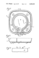
- FIG. 1 is a bottom plan view of a cooker having an irregular channel formed in the underside of said bottom wall and a sheathed heating element fixed therein in accordance with the invention
- FIG. 2 is a sectional view taken on lines 2--2 of FIG. 1, looking in the directions indicated by the arrows;
- FIG. 3 is a fragmented end view of the cooker as viewed from the situs indicated by line 3--3 in FIG. 1;
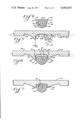
- FIG. 4 illustrates on an enlarged scale a section taken through the sheathed heater element to be staked in the channel
- FIG. 5 is an enlarged sectional view taken through the bottom wall of the cooker to illustrate details of the channel and its formation
- FIG. 6 illustrates the heating element assembled in the receiving channel prior to staking
- FIG. 7 is a view generally similar to FIG. 6 and shows the staked assembly.
- FIGS. 1-3 there is illustrated at 10 an exemplary electric cooker such as a fry pan or casserole having a sheathed electric heater element 40 fixed within a provided irregular channel 20 on its underside in accordance with the invention as hereinafter described.
- the illustrated cooker 10 has a flat bottom wall 12 which contains said channel 20 and a surrounding upturned continuous sidewall 14.
- the bottom wall of the cooker is of generally square shape with rounded corners and it has integrally formed cylinder portions 16 adjacent each of its four corners providing means to which legs (not shown) may be fixed as by screws which threadedly connect into internally threaded openings 18.
- the cooker is formed from wrought metal such as aluminum sheet stock which is pressed to the described shape as by forging or stamping.
- its channel 20 may be formed simultaneously with the forging of the cooker from sheet metal such as aluminum. It also may be formed in a subsequently conducted separate operation after the cooker has been given its required shape.
- channel 20 is defined by a pair of generally parallel-spaced outstanding ribs 22 which project from one side of the cooker wall.
- channel 20 is formed in the underside 24 of the bottom wall 12.
- channel 20 is formed by displacing metal outwardly of side 24 along slight angles (usually about 5°) to the plane of the cooker wall 12 and to the opposed sides of the channel as indicated by arrows 26.
- the displaced metal is then forced outwardly along short arcs 28 of short radii at the sides of the forming channel bottom 30 to produce ribs 22.
- the formed channel bottom 30 thus lies entirely below surface 24 and has the indicated shallow vee-shape in transverse section and merges at its opposed sides along curved surfaces 28 embodying the aforementioned short arcs into the nearly vertical facing surfaces 32 of the two ribs which bound channel 20.
- the inner surfaces 32 of the ribs are not truly vertical but are in divergent relation, possibly 3° off vertical as indicated at y and are spaced apart a distance only slightly greater than the widest lateral dimension of the sheathed electric heater element 40 which is to be located therein as afterwards described.
- the width of the channel bottom 30 on the other hand is only slightly less than said widest lateral dimension of the heater element 40.
- metal is displaced from areas 34 along the outside of the channel.
- Such metal when combined with the metal displaced from the channel bottom 30 is caused to impart a vee or pyramid shape to the ribs 22 in transverse section as illustrated by FIG. 5.
- the metal displaced from areas 34 is to about the same level as channel bottom 30 and is along long but shallow arcs such that at the level of surface 24 the ribs have a substantial thickness and so that their outer surface 36 is inclined at an angle z of approximately 45° to the vertical.
- channel 20 is arranged in the shape of nearly a full circle, the two ends 20a of the channel 20, however, being turned outwardly and disposed in appropriately spaced approximate parallel relation to opposed sides of and generally parallel with groove 19.
- Channel ends 20a serve primarily to locate the termini of the sheathed electric heater element 40 which is fixed in the channel. Therefore the rib formations 22 on either side of the channel may be discontinued at 38 where said channel ends 20a turn outwardly from the circularly-arranged main body of the heating element.
- Channel ends 20a may be separately formed and simultaneously with groove 19; and its bottom wall may be rounded as illustrated in FIG. 3. It may also have a shallow vee-shape similar to that of the channel 20 proper.
- electric heater element 40 includes a resistance coil 42 enclosed within surrounding tubular sheath 44 packed with a dielectric material 46 as is conventional.
- Sheath 44 is of pliant ductile metal such as aluminum.
- sheathed heater element 40 is non-circular in cross section and in its presently preferred form includes a semicircular outer portion 48 with outwardly diverging sides 50 and a flat base 52. Its sheath 44 is of non-uniform thickness, being thickest through its diverging sides 50 and semicircular outer portion 48. Its flat base wall 52 is purposely much thinner. Immediately adjacent its base 52, sides 50 are thickened in cross section into sharply projecting rounded protuberances 54 which extend along the length thereof.
- protuberances are coplanar with and comprise extensions of said flat base 52.
- height or vertical dimension of said protuberances 54 approximates, or is only slightly less than k representing the depth at which channel bottom 30 lies below surface 24 of wall 12.
- heating element 40 is first shaped to the irregular configuration of channel 20 and then located therein with its two ends 40a aligned in channel end portions 20a where they are conveniently accessible from one side of the cooker 10. Thereafter said ends 40a will be provided with terminal pins (not shown) by means of which the resistance coil 42 of the heater element 40 is connectable to an electrical power source utilizing a conventional cord set.
- the treatment of said heater element ends 40a is conventional and since it plays no part of the present invention, it is therefore neither illustrated nor will it be further described.
- heater element 40 when located between ribs 22 with its flat base 52 facing channel bottom 30 is positioned as deep into the channel as it will go. As previously indicated, its width is slightly less than the open mouth of the channel between ribs 22 but more than the width of the channel at bottom 30. As illustrated in FIG. 6, its side edges 56 come to rest approximately at the level of surface 24 or slightly therebelow with side edges 56 abutting arcuate surfaces 28. Base 52 is still a substantial distance from the underlying channel wall 30. Ribs 22 are also of sufficient height that the protuberances 54 lie a substantial distance inwardly of the channel mouth.
- Assembly of the heater element 40 within channel 20 is completed by applying folding pressure to both ribs 22 from exteriorly thereof as indicated by arrows a' and a" while counter or resisting pressure is simultaneously applied to the opposite side 58 as indicated by arrow b.
- the pressure applied at a', a" and b may be achieved utilizing appropriately shaped movable dies; alternatively one of the dies may be fixed and the other movable.
- the dies applying pressure to the exterior surfaces 36 of the ribs will be so shaped as to avoid applying deforming pressure to the rounded outer surface 48 of the sheathed heater which remains exposed in the completed assembly.
- the pressure applied may be in the order of 2,500 tons and is sufficient first to fold or move the ribs inwardly of the channel into close engagement with the outer periphery of said sides 50 and protuberances 54 of the heater element 40 and thereafter, as the dies continue to move inwardly, to effectively compress the protuberances and sides of the heater element between the ribs 22 and the channel bottom 30 causing the thinner base wall 52 of element 40 to bend intermediate its side edges at 60. Simultaneously its side edges 58 pivot and slide inwardly along short arcuate surfaces 28, and slightly deforming, until the base 52 of said element 40 other than its end portions 40a intimately conforms through its full area to the vee-shaped channel bottom 30.
- the material of the sheath across junction 64 of the protuberances 54 is also reshaped and displaced inwardly as indicated by the inward bulge of the sheath wall at 66.
- the assembly of the heater element 40 within the channel 20 is complete.
- the ribs 22 closely grip the confined portions of the heater element.
- the engaged periphery of the sides, protuberances and base of the heater element 40 also closely conform to the inner surface of the ribs and channel base so that there is now established a good heat transfer relation between the heater element sheath 44 and the cooker wall 12.
- the heater element is stabilized against longitudinal movement.
- the exposed outer surface of the heater element has been substantially untouched or deformed in the assembly process and retains its original rounded shape.
Landscapes
- Engineering & Computer Science (AREA)
- Food Science & Technology (AREA)
- Resistance Heating (AREA)
- Cookers (AREA)
Priority Applications (8)
| Application Number | Priority Date | Filing Date | Title |
|---|---|---|---|
| US05/700,110 US4045653A (en) | 1976-06-28 | 1976-06-28 | Electric cooker with press-staked heating element and method of making the same |
| ZA00773063A ZA773063B (en) | 1976-06-28 | 1977-05-23 | Electric appliance with press-staked heating element |
| AU26068/77A AU500248B2 (en) | 1976-06-28 | 1977-06-14 | Electric cooker |
| FR7719646A FR2357139A1 (fr) | 1976-06-28 | 1977-06-27 | Procede de fixation d'une resistance de chauffage dans un ustensile de cuisine electrique |
| LU77636A LU77636A1 (fr) | 1976-06-28 | 1977-06-27 | |
| DE19772729087 DE2729087A1 (de) | 1976-06-28 | 1977-06-28 | Elektrisches gargeraet mit durch pressfuegen befestigtem heizelement |
| NL7707141A NL7707141A (nl) | 1976-06-28 | 1977-06-28 | Elektrische kookpan met een door persen ingezet verwarmingselelement. |
| BE178875A BE856226A (fr) | 1976-06-28 | 1977-06-28 | Perfectionnements relatifs aux appareils de cuisson electriques |
Applications Claiming Priority (1)
| Application Number | Priority Date | Filing Date | Title |
|---|---|---|---|
| US05/700,110 US4045653A (en) | 1976-06-28 | 1976-06-28 | Electric cooker with press-staked heating element and method of making the same |
Publications (1)
| Publication Number | Publication Date |
|---|---|
| US4045653A true US4045653A (en) | 1977-08-30 |
Family
ID=24812228
Family Applications (1)
| Application Number | Title | Priority Date | Filing Date |
|---|---|---|---|
| US05/700,110 Expired - Lifetime US4045653A (en) | 1976-06-28 | 1976-06-28 | Electric cooker with press-staked heating element and method of making the same |
Country Status (8)
| Country | Link |
|---|---|
| US (1) | US4045653A (fr) |
| AU (1) | AU500248B2 (fr) |
| BE (1) | BE856226A (fr) |
| DE (1) | DE2729087A1 (fr) |
| FR (1) | FR2357139A1 (fr) |
| LU (1) | LU77636A1 (fr) |
| NL (1) | NL7707141A (fr) |
| ZA (1) | ZA773063B (fr) |
Cited By (20)
| Publication number | Priority date | Publication date | Assignee | Title |
|---|---|---|---|---|
| FR2369772A1 (fr) * | 1976-10-28 | 1978-05-26 | Nat Presto Ind | Appareil electrique comportant un element chauffant blinde fixe de place en place |
| US4380116A (en) * | 1979-12-14 | 1983-04-19 | E.G.O. Elektro-Gerate Blanc U. Fischer | Radiant electrical heater, as well as method and apparatus for the manufacture thereof |
| US4735300A (en) * | 1982-06-21 | 1988-04-05 | Eaton Corporation | Fluid coupling device, bimetal coil and clip assembly thereof |
| EP0307555A1 (fr) * | 1987-09-15 | 1989-03-22 | Stephan Vandaele | Procédé pour la fabrication d'un récipient de cuisson |
| EP0323348A1 (fr) * | 1987-12-30 | 1989-07-05 | Seb S.A. | Procédé pour réaliser une plaque chauffante et article chauffant s'y rapportant |
| US5046243A (en) * | 1990-11-05 | 1991-09-10 | Gte Products Corporation | Method of mounting electrical contacts in connector body |
| US5189947A (en) * | 1992-06-29 | 1993-03-02 | Chiaphua Industries Limited | Rice and vegetable steamer |
| US5515773A (en) * | 1995-02-16 | 1996-05-14 | The Rival Company | Steam oven |
| FR2730120A1 (fr) * | 1995-02-01 | 1996-08-02 | Seb Sa | Element chauffant avec plaque diffusante |
| WO1996024233A1 (fr) * | 1995-02-01 | 1996-08-08 | Seb S.A. | Element chauffant avec plaque diffusante et procede d'assemblage dudit ensemble |
| USD429596S (en) | 1997-11-21 | 2000-08-22 | The Rival Company | Slow cooker |
| USD434940S (en) * | 2000-02-25 | 2000-12-12 | The Holmes Group | Slow cooker |
| US6408503B1 (en) * | 1999-03-18 | 2002-06-25 | Hotset Heizpatronen U. Zubehor Gmbh | Method of making injection-molder heating element |
| US7053338B1 (en) | 2005-07-08 | 2006-05-30 | Tesfagaber Zekarias K | Electric cooker |
| USD642423S1 (en) | 2011-01-28 | 2011-08-02 | National Presto Industries, Inc. | Skillet having removable base |
| USD643675S1 (en) | 2011-01-28 | 2011-08-23 | National Presto Industries, Inc. | Skillet with removable handles |
| USD658428S1 (en) | 2011-08-05 | 2012-05-01 | National Presto Industries, Inc. | Skillet having removable base |
| US20150165572A1 (en) * | 2013-12-17 | 2015-06-18 | Quanta Computer Inc. | Manufacturing method of heat dissipation assembly |
| USD763034S1 (en) | 2015-03-17 | 2016-08-09 | National Presto Industries, Inc. | Skillet |
| US20180263413A1 (en) * | 2017-03-14 | 2018-09-20 | Illinois Tool Works Inc. | Cooking appliance and related heater assembly |
Citations (7)
| Publication number | Priority date | Publication date | Assignee | Title |
|---|---|---|---|---|
| US2662158A (en) * | 1951-07-28 | 1953-12-08 | Gen Electric | Heating unit and method of making the same |
| US2875312A (en) * | 1956-09-27 | 1959-02-24 | Thermel Inc | Heating assembly and method of production thereof |
| US2987300A (en) * | 1959-05-29 | 1961-06-06 | Edward G S Greene | Heat transfer assembly |
| US3110796A (en) * | 1960-07-15 | 1963-11-12 | Gen Motors Corp | Cooking unit |
| US3221396A (en) * | 1960-07-15 | 1965-12-07 | Gen Motors Corp | Method of forming a solid plate cooking unit |
| US3758750A (en) * | 1971-01-21 | 1973-09-11 | Toorn C Van | Surface heating apparatus having one or more heating elements in its heating |
| US3885128A (en) * | 1974-07-01 | 1975-05-20 | Gen Electric | Glass-ceramic plate heating unit cast-in heat spreader |
-
1976
- 1976-06-28 US US05/700,110 patent/US4045653A/en not_active Expired - Lifetime
-
1977
- 1977-05-23 ZA ZA00773063A patent/ZA773063B/xx unknown
- 1977-06-14 AU AU26068/77A patent/AU500248B2/en not_active Expired
- 1977-06-27 LU LU77636A patent/LU77636A1/xx unknown
- 1977-06-27 FR FR7719646A patent/FR2357139A1/fr not_active Withdrawn
- 1977-06-28 NL NL7707141A patent/NL7707141A/xx not_active Application Discontinuation
- 1977-06-28 BE BE178875A patent/BE856226A/fr unknown
- 1977-06-28 DE DE19772729087 patent/DE2729087A1/de active Pending
Patent Citations (7)
| Publication number | Priority date | Publication date | Assignee | Title |
|---|---|---|---|---|
| US2662158A (en) * | 1951-07-28 | 1953-12-08 | Gen Electric | Heating unit and method of making the same |
| US2875312A (en) * | 1956-09-27 | 1959-02-24 | Thermel Inc | Heating assembly and method of production thereof |
| US2987300A (en) * | 1959-05-29 | 1961-06-06 | Edward G S Greene | Heat transfer assembly |
| US3110796A (en) * | 1960-07-15 | 1963-11-12 | Gen Motors Corp | Cooking unit |
| US3221396A (en) * | 1960-07-15 | 1965-12-07 | Gen Motors Corp | Method of forming a solid plate cooking unit |
| US3758750A (en) * | 1971-01-21 | 1973-09-11 | Toorn C Van | Surface heating apparatus having one or more heating elements in its heating |
| US3885128A (en) * | 1974-07-01 | 1975-05-20 | Gen Electric | Glass-ceramic plate heating unit cast-in heat spreader |
Cited By (25)
| Publication number | Priority date | Publication date | Assignee | Title |
|---|---|---|---|---|
| FR2369772A1 (fr) * | 1976-10-28 | 1978-05-26 | Nat Presto Ind | Appareil electrique comportant un element chauffant blinde fixe de place en place |
| US4115918A (en) * | 1976-10-28 | 1978-09-26 | National Presto Industries, Inc. | Method of making electric appliance with intermittently staked sheathed heating element |
| US4380116A (en) * | 1979-12-14 | 1983-04-19 | E.G.O. Elektro-Gerate Blanc U. Fischer | Radiant electrical heater, as well as method and apparatus for the manufacture thereof |
| US4735300A (en) * | 1982-06-21 | 1988-04-05 | Eaton Corporation | Fluid coupling device, bimetal coil and clip assembly thereof |
| EP0307555A1 (fr) * | 1987-09-15 | 1989-03-22 | Stephan Vandaele | Procédé pour la fabrication d'un récipient de cuisson |
| EP0323348A1 (fr) * | 1987-12-30 | 1989-07-05 | Seb S.A. | Procédé pour réaliser une plaque chauffante et article chauffant s'y rapportant |
| FR2625641A1 (fr) * | 1987-12-30 | 1989-07-07 | Seb Sa | Procede pour realiser une plaque chauffante et article chauffant s'y rapportant |
| US4913338A (en) * | 1987-12-30 | 1990-04-03 | Seb S.A. | Process for producing a heating plate and heating article relating to this |
| US5046243A (en) * | 1990-11-05 | 1991-09-10 | Gte Products Corporation | Method of mounting electrical contacts in connector body |
| US5189947A (en) * | 1992-06-29 | 1993-03-02 | Chiaphua Industries Limited | Rice and vegetable steamer |
| WO1996024233A1 (fr) * | 1995-02-01 | 1996-08-08 | Seb S.A. | Element chauffant avec plaque diffusante et procede d'assemblage dudit ensemble |
| FR2730120A1 (fr) * | 1995-02-01 | 1996-08-02 | Seb Sa | Element chauffant avec plaque diffusante |
| US5515773A (en) * | 1995-02-16 | 1996-05-14 | The Rival Company | Steam oven |
| USD429596S (en) | 1997-11-21 | 2000-08-22 | The Rival Company | Slow cooker |
| US6408503B1 (en) * | 1999-03-18 | 2002-06-25 | Hotset Heizpatronen U. Zubehor Gmbh | Method of making injection-molder heating element |
| USD434940S (en) * | 2000-02-25 | 2000-12-12 | The Holmes Group | Slow cooker |
| US7053338B1 (en) | 2005-07-08 | 2006-05-30 | Tesfagaber Zekarias K | Electric cooker |
| USD642423S1 (en) | 2011-01-28 | 2011-08-02 | National Presto Industries, Inc. | Skillet having removable base |
| USD643675S1 (en) | 2011-01-28 | 2011-08-23 | National Presto Industries, Inc. | Skillet with removable handles |
| USD658428S1 (en) | 2011-08-05 | 2012-05-01 | National Presto Industries, Inc. | Skillet having removable base |
| US20150165572A1 (en) * | 2013-12-17 | 2015-06-18 | Quanta Computer Inc. | Manufacturing method of heat dissipation assembly |
| US9381599B2 (en) * | 2013-12-17 | 2016-07-05 | Quanta Computer Inc. | Manufacturing method of heat dissipation assembly |
| USD763034S1 (en) | 2015-03-17 | 2016-08-09 | National Presto Industries, Inc. | Skillet |
| US20180263413A1 (en) * | 2017-03-14 | 2018-09-20 | Illinois Tool Works Inc. | Cooking appliance and related heater assembly |
| US11154162B2 (en) * | 2017-03-14 | 2021-10-26 | Illinois Tool Works Inc. | Cooking appliance and related heater assembly |
Also Published As
| Publication number | Publication date |
|---|---|
| AU500248B2 (en) | 1979-05-17 |
| AU2606877A (en) | 1978-07-13 |
| FR2357139A1 (fr) | 1978-01-27 |
| BE856226A (fr) | 1977-10-17 |
| LU77636A1 (fr) | 1977-10-03 |
| ZA773063B (en) | 1978-04-26 |
| DE2729087A1 (de) | 1978-01-05 |
| NL7707141A (nl) | 1977-12-30 |
Similar Documents
| Publication | Publication Date | Title |
|---|---|---|
| US4045653A (en) | Electric cooker with press-staked heating element and method of making the same | |
| US4052590A (en) | Electric appliance with intermittently staked sheathed heating element | |
| JP2747160B2 (ja) | シールドケース | |
| CN104334066B (zh) | 配备有热电偶的烹饪装置 | |
| US2288348A (en) | Welding equipment | |
| GB1590217A (en) | Micro-soldering tool | |
| US3112150A (en) | Electrical connections | |
| KR20190086381A (ko) | 와이어들을 연결하기 위한 크림프 | |
| US2256637A (en) | Wiee coupling and method of | |
| EP0404349B1 (fr) | Ensemble de matrices de sertissage et méthode de sertissage d'une borne électrique | |
| US3032602A (en) | Electrical connector | |
| US2878854A (en) | Wire gripping crimping dies with rib receiving grooves | |
| EP1660254B1 (fr) | Procede pour produire un ustensile de cuisine, notamment une casserole, une poele ou autre element similaire | |
| US1937431A (en) | Process of making cable terminals | |
| US4066201A (en) | Method of joining metal parts | |
| US2987697A (en) | Electric connector | |
| US4481407A (en) | Electric hotplate | |
| EP0765625A1 (fr) | Améliorations pour ou concernant Woks | |
| US3300621A (en) | Electric hotplate and method of making same | |
| US4658118A (en) | Electric hotplate | |
| US2032926A (en) | Electrical contact | |
| DE69607939T2 (de) | Heizelement mit streuscheibe und verfahren zum zusammenbauen der beiden | |
| US3533055A (en) | Electrical connector and method and apparatus for making same | |
| US2937261A (en) | Electric cooking vessel and method of making same | |
| CA2140583A1 (fr) | Contact a sertir pour fils electriques |