US4045711A - Tuned oscillator ballast circuit - Google Patents
Tuned oscillator ballast circuit Download PDFInfo
- Publication number
- US4045711A US4045711A US05/668,485 US66848576A US4045711A US 4045711 A US4045711 A US 4045711A US 66848576 A US66848576 A US 66848576A US 4045711 A US4045711 A US 4045711A
- Authority
- US
- United States
- Prior art keywords
- winding
- inductive
- oscillator
- circuit
- potential source
- Prior art date
- Legal status (The legal status is an assumption and is not a legal conclusion. Google has not performed a legal analysis and makes no representation as to the accuracy of the status listed.)
- Expired - Lifetime
Links
- 238000004804 winding Methods 0.000 claims abstract description 68
- 239000003990 capacitor Substances 0.000 claims abstract description 29
- 230000001939 inductive effect Effects 0.000 claims description 45
- 230000000694 effects Effects 0.000 claims description 14
- 239000002184 metal Substances 0.000 claims description 13
- 230000008878 coupling Effects 0.000 claims description 8
- 238000010168 coupling process Methods 0.000 claims description 8
- 238000005859 coupling reaction Methods 0.000 claims description 8
- 230000010363 phase shift Effects 0.000 claims 2
- 230000004913 activation Effects 0.000 claims 1
- 238000010438 heat treatment Methods 0.000 claims 1
- 239000011162 core material Substances 0.000 description 3
- 230000002939 deleterious effect Effects 0.000 description 2
- 230000006378 damage Effects 0.000 description 1
- 230000007812 deficiency Effects 0.000 description 1
- 238000009499 grossing Methods 0.000 description 1
- 238000000034 method Methods 0.000 description 1
- 238000012986 modification Methods 0.000 description 1
- 230000004048 modification Effects 0.000 description 1
- 239000002699 waste material Substances 0.000 description 1
Images
Classifications
-
- H—ELECTRICITY
- H02—GENERATION; CONVERSION OR DISTRIBUTION OF ELECTRIC POWER
- H02M—APPARATUS FOR CONVERSION BETWEEN AC AND AC, BETWEEN AC AND DC, OR BETWEEN DC AND DC, AND FOR USE WITH MAINS OR SIMILAR POWER SUPPLY SYSTEMS; CONVERSION OF DC OR AC INPUT POWER INTO SURGE OUTPUT POWER; CONTROL OR REGULATION THEREOF
- H02M7/00—Conversion of AC power input into DC power output; Conversion of DC power input into AC power output
- H02M7/42—Conversion of DC power input into AC power output without possibility of reversal
- H02M7/44—Conversion of DC power input into AC power output without possibility of reversal by static converters
- H02M7/48—Conversion of DC power input into AC power output without possibility of reversal by static converters using discharge tubes with control electrode or semiconductor devices with control electrode
- H02M7/53—Conversion of DC power input into AC power output without possibility of reversal by static converters using discharge tubes with control electrode or semiconductor devices with control electrode using devices of a triode or transistor type requiring continuous application of a control signal
- H02M7/537—Conversion of DC power input into AC power output without possibility of reversal by static converters using discharge tubes with control electrode or semiconductor devices with control electrode using devices of a triode or transistor type requiring continuous application of a control signal using semiconductor devices only, e.g. single switched pulse inverters
- H02M7/5383—Conversion of DC power input into AC power output without possibility of reversal by static converters using discharge tubes with control electrode or semiconductor devices with control electrode using devices of a triode or transistor type requiring continuous application of a control signal using semiconductor devices only, e.g. single switched pulse inverters in a self-oscillating arrangement
- H02M7/53846—Control circuits
- H02M7/53862—Control circuits using transistor type converters
-
- H—ELECTRICITY
- H02—GENERATION; CONVERSION OR DISTRIBUTION OF ELECTRIC POWER
- H02M—APPARATUS FOR CONVERSION BETWEEN AC AND AC, BETWEEN AC AND DC, OR BETWEEN DC AND DC, AND FOR USE WITH MAINS OR SIMILAR POWER SUPPLY SYSTEMS; CONVERSION OF DC OR AC INPUT POWER INTO SURGE OUTPUT POWER; CONTROL OR REGULATION THEREOF
- H02M5/00—Conversion of AC power input into AC power output, e.g. for change of voltage, for change of frequency, for change of number of phases
- H02M5/40—Conversion of AC power input into AC power output, e.g. for change of voltage, for change of frequency, for change of number of phases with intermediate conversion into DC
- H02M5/42—Conversion of AC power input into AC power output, e.g. for change of voltage, for change of frequency, for change of number of phases with intermediate conversion into DC by static converters
- H02M5/44—Conversion of AC power input into AC power output, e.g. for change of voltage, for change of frequency, for change of number of phases with intermediate conversion into DC by static converters using discharge tubes or semiconductor devices to convert the intermediate DC into AC
- H02M5/453—Conversion of AC power input into AC power output, e.g. for change of voltage, for change of frequency, for change of number of phases with intermediate conversion into DC by static converters using discharge tubes or semiconductor devices to convert the intermediate DC into AC using devices of a triode or transistor type requiring continuous application of a control signal
- H02M5/458—Conversion of AC power input into AC power output, e.g. for change of voltage, for change of frequency, for change of number of phases with intermediate conversion into DC by static converters using discharge tubes or semiconductor devices to convert the intermediate DC into AC using devices of a triode or transistor type requiring continuous application of a control signal using semiconductor devices only
-
- H—ELECTRICITY
- H02—GENERATION; CONVERSION OR DISTRIBUTION OF ELECTRIC POWER
- H02M—APPARATUS FOR CONVERSION BETWEEN AC AND AC, BETWEEN AC AND DC, OR BETWEEN DC AND DC, AND FOR USE WITH MAINS OR SIMILAR POWER SUPPLY SYSTEMS; CONVERSION OF DC OR AC INPUT POWER INTO SURGE OUTPUT POWER; CONTROL OR REGULATION THEREOF
- H02M7/00—Conversion of AC power input into DC power output; Conversion of DC power input into AC power output
- H02M7/42—Conversion of DC power input into AC power output without possibility of reversal
- H02M7/44—Conversion of DC power input into AC power output without possibility of reversal by static converters
- H02M7/48—Conversion of DC power input into AC power output without possibility of reversal by static converters using discharge tubes with control electrode or semiconductor devices with control electrode
- H02M7/53—Conversion of DC power input into AC power output without possibility of reversal by static converters using discharge tubes with control electrode or semiconductor devices with control electrode using devices of a triode or transistor type requiring continuous application of a control signal
- H02M7/537—Conversion of DC power input into AC power output without possibility of reversal by static converters using discharge tubes with control electrode or semiconductor devices with control electrode using devices of a triode or transistor type requiring continuous application of a control signal using semiconductor devices only, e.g. single switched pulse inverters
- H02M7/538—Conversion of DC power input into AC power output without possibility of reversal by static converters using discharge tubes with control electrode or semiconductor devices with control electrode using devices of a triode or transistor type requiring continuous application of a control signal using semiconductor devices only, e.g. single switched pulse inverters in a push-pull configuration
-
- H—ELECTRICITY
- H02—GENERATION; CONVERSION OR DISTRIBUTION OF ELECTRIC POWER
- H02M—APPARATUS FOR CONVERSION BETWEEN AC AND AC, BETWEEN AC AND DC, OR BETWEEN DC AND DC, AND FOR USE WITH MAINS OR SIMILAR POWER SUPPLY SYSTEMS; CONVERSION OF DC OR AC INPUT POWER INTO SURGE OUTPUT POWER; CONTROL OR REGULATION THEREOF
- H02M7/00—Conversion of AC power input into DC power output; Conversion of DC power input into AC power output
- H02M7/42—Conversion of DC power input into AC power output without possibility of reversal
- H02M7/44—Conversion of DC power input into AC power output without possibility of reversal by static converters
- H02M7/48—Conversion of DC power input into AC power output without possibility of reversal by static converters using discharge tubes with control electrode or semiconductor devices with control electrode
- H02M7/53—Conversion of DC power input into AC power output without possibility of reversal by static converters using discharge tubes with control electrode or semiconductor devices with control electrode using devices of a triode or transistor type requiring continuous application of a control signal
- H02M7/537—Conversion of DC power input into AC power output without possibility of reversal by static converters using discharge tubes with control electrode or semiconductor devices with control electrode using devices of a triode or transistor type requiring continuous application of a control signal using semiconductor devices only, e.g. single switched pulse inverters
- H02M7/5383—Conversion of DC power input into AC power output without possibility of reversal by static converters using discharge tubes with control electrode or semiconductor devices with control electrode using devices of a triode or transistor type requiring continuous application of a control signal using semiconductor devices only, e.g. single switched pulse inverters in a self-oscillating arrangement
- H02M7/53846—Control circuits
-
- H—ELECTRICITY
- H05—ELECTRIC TECHNIQUES NOT OTHERWISE PROVIDED FOR
- H05B—ELECTRIC HEATING; ELECTRIC LIGHT SOURCES NOT OTHERWISE PROVIDED FOR; CIRCUIT ARRANGEMENTS FOR ELECTRIC LIGHT SOURCES, IN GENERAL
- H05B41/00—Circuit arrangements or apparatus for igniting or operating discharge lamps
- H05B41/14—Circuit arrangements
- H05B41/26—Circuit arrangements in which the lamp is fed by power derived from DC by means of a converter, e.g. by high-voltage DC
- H05B41/28—Circuit arrangements in which the lamp is fed by power derived from DC by means of a converter, e.g. by high-voltage DC using static converters
- H05B41/282—Circuit arrangements in which the lamp is fed by power derived from DC by means of a converter, e.g. by high-voltage DC using static converters with semiconductor devices
- H05B41/285—Arrangements for protecting lamps or circuits against abnormal operating conditions
- H05B41/2851—Arrangements for protecting lamps or circuits against abnormal operating conditions for protecting the circuit against abnormal operating conditions
- H05B41/2855—Arrangements for protecting lamps or circuits against abnormal operating conditions for protecting the circuit against abnormal operating conditions against abnormal lamp operating conditions
-
- Y—GENERAL TAGGING OF NEW TECHNOLOGICAL DEVELOPMENTS; GENERAL TAGGING OF CROSS-SECTIONAL TECHNOLOGIES SPANNING OVER SEVERAL SECTIONS OF THE IPC; TECHNICAL SUBJECTS COVERED BY FORMER USPC CROSS-REFERENCE ART COLLECTIONS [XRACs] AND DIGESTS
- Y02—TECHNOLOGIES OR APPLICATIONS FOR MITIGATION OR ADAPTATION AGAINST CLIMATE CHANGE
- Y02B—CLIMATE CHANGE MITIGATION TECHNOLOGIES RELATED TO BUILDINGS, e.g. HOUSING, HOUSE APPLIANCES OR RELATED END-USER APPLICATIONS
- Y02B70/00—Technologies for an efficient end-user side electric power management and consumption
- Y02B70/10—Technologies improving the efficiency by using switched-mode power supplies [SMPS], i.e. efficient power electronics conversion e.g. power factor correction or reduction of losses in power supplies or efficient standby modes
-
- Y—GENERAL TAGGING OF NEW TECHNOLOGICAL DEVELOPMENTS; GENERAL TAGGING OF CROSS-SECTIONAL TECHNOLOGIES SPANNING OVER SEVERAL SECTIONS OF THE IPC; TECHNICAL SUBJECTS COVERED BY FORMER USPC CROSS-REFERENCE ART COLLECTIONS [XRACs] AND DIGESTS
- Y10—TECHNICAL SUBJECTS COVERED BY FORMER USPC
- Y10S—TECHNICAL SUBJECTS COVERED BY FORMER USPC CROSS-REFERENCE ART COLLECTIONS [XRACs] AND DIGESTS
- Y10S315/00—Electric lamp and discharge devices: systems
- Y10S315/02—High frequency starting operation for fluorescent lamp
-
- Y—GENERAL TAGGING OF NEW TECHNOLOGICAL DEVELOPMENTS; GENERAL TAGGING OF CROSS-SECTIONAL TECHNOLOGIES SPANNING OVER SEVERAL SECTIONS OF THE IPC; TECHNICAL SUBJECTS COVERED BY FORMER USPC CROSS-REFERENCE ART COLLECTIONS [XRACs] AND DIGESTS
- Y10—TECHNICAL SUBJECTS COVERED BY FORMER USPC
- Y10S—TECHNICAL SUBJECTS COVERED BY FORMER USPC CROSS-REFERENCE ART COLLECTIONS [XRACs] AND DIGESTS
- Y10S315/00—Electric lamp and discharge devices: systems
- Y10S315/05—Starting and operating circuit for fluorescent lamp
Definitions
- This invention relates to oscillator ballast circuits and is particularly suited to use with 35 and 40-watt fluorescent lamps.
- fluorescent lamp ballast circuits in presentday use are of the auto-transformer type whereby the lamp is rendered non-conductive at a 120-Hz rate. Since auto-transformers are notoriously heavy, inefficient, and expensive, it can readily be seen that such apparatus is undesirable in view of the energy waste, excessive heat generated, and cost. Moreover, the non-conductivity rate of 120 Hz is well within the audio range and tends to provide undesired audible noise.
- lamp ballast circuitry employs a flip-flop type oscillator circuit in cooperation with a saturable core transformer.
- a transistor of the oscillator saturates and effects saturation of the transformer core material to limit current flow and inhibit lamp burnout.
- core material saturation characteristics are erratic and unpredictable which renders such circuitry undesirable or at best, most difficult to predict or control.
- ballast circuitry In still another known form of ballast circuitry, an oscillator circuit is combined with a series resonant inductor and capacitor. Another inductor is placed in series connection with the series resonant circuit and provides drive potentials for the oscillator. Moreover, a load circuit is shunted across the capacitor.
- ballast circuit has numerous advantages over other known techniques, it has been found that there are deficiencies which tend to inhibit its use. For example, it has been found that increased current flow through the inductor driving the transistors occurs when the load is removed and this increased current flow causes failure of the transistors of the oscillator circuit. Also, short circuiting the load circuit tends to cause failure of the oscillator transistors. Moreover, several transformers are required and no provision is made for tuning the oscillator circuitry to effect switching of the transistors at a minimum or zero current level whereby power losses are reduced. Also, no provisions are made for power factor correction.
- An object of the present invention is to provide an enhanced oscillator ballast circuit. Still another object of the invention is to provide an oscillator ballast circuit having overload protection. A further object of the invention is to provide an oscillator ballast circuit having both open circuit and short circuit protection circuitry. A still further object of the invention is to provide an improved oscillator ballast circuit having ambient and current flow temperature protection circuitry. A final objective is to provide for power factor correction.
- an oscillator ballast circuit having an oscillator circuit coupled to a pulsed DC potential source and to an output transformer having a first winding connected to the oscillator circuit and to a capacitor forming a series resonant circuit, a second winding inductively coupled to the first winding and to the oscillator circuit to effect drive potentials for the oscillator, a third winding shunting the capacitor and coupled to a lamp load, and a fourth winding inductively coupled to the first winding and to the pulsed DC potential source to effect clamping of the potential source at a given potential level.
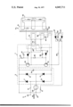
- the sole FIGURE illustrates a tuned oscillator ballast circuit for fluorescent lamps and having overload protection circuitry.
- a tuned oscillator ballast circuit includes an AC potential source 3 coupled to a DC rectifier means 5.
- An oscillator circuit 7 is coupled to the DC rectifier means 5 and to a transformer means 9.
- the DC rectifier means 5 includes first, second, third, and fourth diodes 11, 13, 15, and 17 in a bridge configuration with an RF capacitor 19 shunting the series connected first and second diodes 11 and 13 and the series connected third and fourth diodes 15 and 17.
- the junction of the first and second diodes 11 and 13 is connected via an RF filter choke 21 to a first terminal 23 of the AC potential source 3.
- the junction of the third and fourth diodes 15 and 17 is connected via a bi-metal switch 25 to the second terminal 27 of the AC potential source 3.
- the oscillator circuit 7 includes first and second transistors 29, and 31, series connected across the RF capacitor 19 of the DC rectifier means 5.
- Each of the first and second transistors 29 and 31 has a bias circuit coupled to the base thereof with each bias circuit including a resistor 33 and 35; capacitor 37 and 39, and diode 41 and 43 respectively.
- a single transformer 9 includes a first inductive winding 45 in series connection with a capacitor 47 to provide a series resonant circuit directly connected to the junction of the first and second series connected transistors 29 and 31 of the oscillator circuit 7.
- a second inductive winding 49 is loosely coupled inductively to the first inductive winding 45 of the transformer 9 and directly coupled to the bias circuits of each of the first and second transistors 29 and 31 of the oscillator circuit 7.
- a third inductive winding 51 of the transformer 9 is in series connection with a capacitor 53 and shunted across the series resonant circuit which includes the first winding 45 and capacitor 47.
- This third inductive winding 51 is coupled to a shunting load circuit 55 which in this example is a pair of fluorescent lamps.
- a fourth inductive winding 57 of the transformer 9 has a center tap 59 and a pair of output terminals 61 and 63.
- the center tap 59 is coupled by a high frequency smoothing choke 65 to a common lead of the DC rectifier means 5 and oscillator circuit 7.
- Each one of the output terminals 61 and 63 of the fourth inductive winding 57 is connected to a diode 67 and 69.
- the diodes 67 and 69 are connected by a common lead to a resistor 71, associated with the bi-metal switch 25, and coupled to the DC rectifier means 5.
- a fifth inductive winding 73 in series connection with an impedance 75 inductively couples a signal from the transformer means 9 to the second inductive winding 49 providing drive signals to the first and second transistors 29 and 31 of the oscillator circuit 7.
- the drive signals are shifted in phase by an amount sufficient to compensate for the well known storage time of the first and second transistors 29 and 31 whereupon transistor switching is effected at the desired zero current level.
- a potential from the AC potential source 3 is applied via the RF filter choke 21 and the bi-metal switch 25 to the bridge configuration of the DC rectifier means 5.
- the DC rectifier means 5 provides a 120 Hz pulsating DC potential which is applied to an oscillator circuit 7 operating, in this example at a frequency of about 33 KHz.
- the load circuit includes the shunt coupled flourescent lamps 55.
- the fifth inductive winding 73 is inductively coupled to the first inductive winding 45 and to the second loosely coupled winding 49 for providing drive signals to the oscillator circuit 7.
- the fifth inductive winding 73 in conjunction with the impedance 75 serves to cause the base current to lead the collector current of the first and second transistors 29 and 31 by several degrees. In this manner, compensation is made for the storage time and the transistors switch at zero current whereupon power losses are substantially eliminated or at least reduced.
- the above-mentioned undesired increase in current flow through the series resonant circuit and burn out of the transistors of the oscillator circuit 7 is substantially eliminated by the addition of the fourth inductive winding 57 and associated diodes 67 and 69.
- the series resonant circuit which includes the first winding 45 and capacitor 47
- the potential at the fourth winding 57 increases causing conduction of the diodes 67 and 69.
- current is fed back to the DC rectifier 5 to prevent further increase in potential thereacross.
- the diodes 67 and 69 serve to effect clamping of winding 57 and inhibit an unrestrained increase in current through winding 45 which would be deleterious to the oscillator circuit 7.
- the bi-metal switch 25 which is included in the circuitry to provide protection from undesired ambient temperature increases is also utilized to effect protection of undesired current increases. Specifically, by placing the impedance 71, a resistor in this example, in the immediate area of the bi-metal switch 25, any increase in current flow in the series resonant circuit which is translated into current flow in the clamping circuitry 57 serves to activate the bi-metal switch 25. In this manner the AC potential source is interrupted for a period sufficient to serve as a warning of improper operation of the apparatus.
- the input current is sinusoidal and in phase with the AC potential source 3.
- the 33 KHz current drawn by oscillator 7 is filtered from the AC potential source 3 by the RF filter choke 21 and RF capacitor 19.
- power factor is corrected and near unity since the AC source's voltage and current are in phase and non-distorted.
- a unique high power factor tuned oscillator ballast circuit especially suitable for use with 35 and 40 watt flourescent lamps.
- the apparatus is fabricated of light weight components which have improved efficiency and reduced heat developing characteristics as compared with other known apparatus. Operation is at a frequency above the audio range whereby undesired noise is virtually eliminated.
- the apparatus includes thermal protection as well as protection upon removal of the load or lamps from the circuitry.
Landscapes
- Engineering & Computer Science (AREA)
- Power Engineering (AREA)
- Circuit Arrangements For Discharge Lamps (AREA)
Priority Applications (8)
| Application Number | Priority Date | Filing Date | Title |
|---|---|---|---|
| US05/668,485 US4045711A (en) | 1976-03-19 | 1976-03-19 | Tuned oscillator ballast circuit |
| GB264877A GB1556292A (en) | 1976-03-19 | 1977-01-21 | Tuned oscillator ballast circuit for fluorescent lamps |
| NL7701676A NL7701676A (nl) | 1976-03-19 | 1977-02-17 | Ballastketen met afgestemde oscillator. |
| CA272,089A CA1079344A (fr) | 1976-03-19 | 1977-02-18 | Regulateur a oscillateur accorde |
| DE19772710036 DE2710036A1 (de) | 1976-03-19 | 1977-03-08 | Abgestimmter vorschaltschwingkreis |
| JP2876377A JPS52113577A (en) | 1976-03-19 | 1977-03-17 | Tuning oscillator stabilizing circuit |
| BE2055749A BE852598A (fr) | 1976-03-19 | 1977-03-18 | Circuit auto-oscillateur reglable |
| IT21417/77A IT1084913B (it) | 1976-03-19 | 1977-03-21 | Circuito zavorra con oscillatore sintonizzato |
Applications Claiming Priority (1)
| Application Number | Priority Date | Filing Date | Title |
|---|---|---|---|
| US05/668,485 US4045711A (en) | 1976-03-19 | 1976-03-19 | Tuned oscillator ballast circuit |
Publications (1)
| Publication Number | Publication Date |
|---|---|
| US4045711A true US4045711A (en) | 1977-08-30 |
Family
ID=24682486
Family Applications (1)
| Application Number | Title | Priority Date | Filing Date |
|---|---|---|---|
| US05/668,485 Expired - Lifetime US4045711A (en) | 1976-03-19 | 1976-03-19 | Tuned oscillator ballast circuit |
Country Status (7)
| Country | Link |
|---|---|
| US (1) | US4045711A (fr) |
| JP (1) | JPS52113577A (fr) |
| BE (1) | BE852598A (fr) |
| CA (1) | CA1079344A (fr) |
| DE (1) | DE2710036A1 (fr) |
| IT (1) | IT1084913B (fr) |
| NL (1) | NL7701676A (fr) |
Cited By (40)
| Publication number | Priority date | Publication date | Assignee | Title |
|---|---|---|---|---|
| US4075476A (en) * | 1976-12-20 | 1978-02-21 | Gte Sylvania Incorporated | Sinusoidal wave oscillator ballast circuit |
| US4109307A (en) * | 1977-05-04 | 1978-08-22 | Gte Sylvania Incorporated | High power factor conversion circuitry |
| US4127795A (en) * | 1977-08-19 | 1978-11-28 | Gte Sylvania Incorporated | Lamp ballast circuit |
| US4127893A (en) * | 1977-08-17 | 1978-11-28 | Gte Sylvania Incorporated | Tuned oscillator ballast circuit with transient compensating means |
| FR2400819A1 (fr) * | 1977-08-17 | 1979-03-16 | Gte Sylvania Inc | Circuit ballast pour lampes fluorescentes |
| DE2941822A1 (de) * | 1979-10-16 | 1981-04-30 | Patra Patent Treuhand | Vorschaltanordnung zum betreiben von niederdruckentladungslampen |
| US4276496A (en) * | 1978-06-13 | 1981-06-30 | Arena Ochoa Guido | Gas discharge lamp employing a pulse generator with a double stage amplification circuit |
| US4398126A (en) * | 1981-03-30 | 1983-08-09 | Patent-Truehand-Gesellschaft Fur Elektrische Gluhlampen Gmbh | Protected low-pressure discharge lamp operating circuit |
| US4424468A (en) | 1981-07-06 | 1984-01-03 | Zelina Francis J | Inverter ballast circuit with shoot through prevention, auto transformer coupling and overload prevention |
| US4459516A (en) * | 1981-07-06 | 1984-07-10 | Zelina William B | Line operated fluorescent lamp inverter ballast |
| US4469988A (en) * | 1980-06-23 | 1984-09-04 | Cronin Donald L | Electronic ballast having emitter coupled transistors and bias circuit between secondary winding and the emitters |
| US4503362A (en) * | 1983-06-01 | 1985-03-05 | Intent Patent A.G. | Frequency stabilized, gain controlled ballast system |
| WO1985001180A1 (fr) * | 1983-09-06 | 1985-03-14 | Oy Helvar | Circuit onduleur ayant un circuit de commande pour amener plus efficacement des transistors a un etat de mise hors tension |
| US4506195A (en) * | 1983-02-04 | 1985-03-19 | North American Philips Lighting Corporation | Apparatus for operating HID lamp at high frequency with high power factor and for providing standby lighting |
| US4508996A (en) * | 1980-06-23 | 1985-04-02 | Brigham Young University | High frequency supply system for gas discharge lamps and electronic ballast therefor |
| US4511823A (en) * | 1982-06-01 | 1985-04-16 | Eaton William L | Reduction of harmonics in gas discharge lamp ballasts |
| US4538094A (en) * | 1983-08-12 | 1985-08-27 | Iota Engineering Co. | Lamp ballast with near unity power factor and low harmonic content |
| US4572990A (en) * | 1983-11-23 | 1986-02-25 | International Energy Conservation Systems | Electronic transformer system for neon lamps |
| US4609852A (en) * | 1983-08-12 | 1986-09-02 | Iota Engineering Co. | Lamp ballast with near unity power factor and low harmonic content |
| US4617533A (en) * | 1984-02-17 | 1986-10-14 | Siemens Aktiengesellschaft | Circuit arrangement for a blocking oscillator switching power unit |
| US4641061A (en) * | 1985-04-22 | 1987-02-03 | Emerson Electric Co. | Solid state ballast for gaseous discharge lamps |
| US4652797A (en) * | 1985-01-22 | 1987-03-24 | Nilssen Ole K | Electronic ballast with high power factor |
| US4684850A (en) * | 1985-09-23 | 1987-08-04 | Stevens Carlile R | Variable frequency bridge inverter for driving gas discharge lamps |
| US4694224A (en) * | 1983-10-19 | 1987-09-15 | Hitachi Lighting, Ltd. | Lighting apparatus for an electric discharge lamp |
| US4857806A (en) * | 1980-08-14 | 1989-08-15 | Nilssen Ole K | Self-ballasted screw-in fluorescent lamp |
| USRE33057E (en) * | 1980-06-23 | 1989-09-12 | Brigham Young University | High frequency supply system for gas discharge lamps and electronic ballast therefor |
| DE2954614C2 (fr) * | 1979-10-16 | 1989-10-19 | Patent-Treuhand-Gesellschaft Fuer Elektrische Gluehlampen Mbh, 8000 Muenchen, De | |
| WO1989011204A1 (fr) * | 1988-05-13 | 1989-11-16 | Han Lim Electronic Co., Ltd. | Stabilisateur electronique pour lampe fluorescente |
| US4888525A (en) * | 1985-05-17 | 1989-12-19 | Nilssen Ole K | Sun tanning apparatus having electronic operating system |
| US4928039A (en) * | 1984-12-04 | 1990-05-22 | Nilssen Ole K | Electronic ballast with lamp pre-conditioning |
| US5004959A (en) * | 1986-04-21 | 1991-04-02 | Nilssen Ole K | Fluorescent lamp ballast with adjustable lamp current |
| US5019959A (en) * | 1988-09-19 | 1991-05-28 | Innovative Controls, Inc. | Ballast circuit |
| US5021717A (en) * | 1989-10-02 | 1991-06-04 | Nilssen Ole K | Operating system for multiple fluorescent lamps |
| US5343124A (en) * | 1980-08-14 | 1994-08-30 | Nilssen Ole K | Shock-hazard-free lighting means |
| WO1994019919A1 (fr) * | 1993-02-16 | 1994-09-01 | Motorola Lighting, Inc. | Circuit d'excitation d'une lampe a decharge a facteur d'alimentation eleve |
| US5416388A (en) * | 1993-12-09 | 1995-05-16 | Motorola Lighting, Inc. | Electronic ballast with two transistors and two transformers |
| US5469028A (en) * | 1978-03-20 | 1995-11-21 | Nilssen; Ole K. | Electronic ballast drawing sinusoidal line current |
| US6057652A (en) * | 1995-09-25 | 2000-05-02 | Matsushita Electric Works, Ltd. | Power supply for supplying AC output power |
| US6211625B1 (en) * | 1980-08-14 | 2001-04-03 | Ole K. Nilssen | Electronic ballast with over-voltage protection |
| US20080150447A1 (en) * | 2006-12-23 | 2008-06-26 | Shackle Peter W | Electronic ballasts |
Families Citing this family (1)
| Publication number | Priority date | Publication date | Assignee | Title |
|---|---|---|---|---|
| DE4120269C2 (de) * | 1991-06-19 | 1995-12-07 | Siemens Ag | Wechselrichter zum Zünden und Betreiben einer Entladungslampe mit heizbaren Elektroden |
Citations (8)
| Publication number | Priority date | Publication date | Assignee | Title |
|---|---|---|---|---|
| US3008068A (en) * | 1958-07-26 | 1961-11-07 | Philips Corp | Transistor voltage converter |
| US3611021A (en) * | 1970-04-06 | 1971-10-05 | North Electric Co | Control circuit for providing regulated current to lamp load |
| US3723848A (en) * | 1972-04-17 | 1973-03-27 | Martin Marietta Corp | Electrical power inverter with sinusoidal output |
| US3753076A (en) * | 1972-04-27 | 1973-08-14 | Lighting Systems Inc | Inverter circuit and switching means |
| US3754160A (en) * | 1971-10-28 | 1973-08-21 | Radiant Ind Inc | Four-lamp driver circuit for fluorescent lamps |
| US3758841A (en) * | 1971-11-11 | 1973-09-11 | Gen Motors Corp | Dc to ac static power converter with short circuit protection |
| US3769545A (en) * | 1972-05-25 | 1973-10-30 | Kodan Inc | Circuit arrangement for operating electric arc discharge devices |
| US3889153A (en) * | 1973-10-01 | 1975-06-10 | Iota Engineering Inc | Power source for fluorescent lamps and the like |
-
1976
- 1976-03-19 US US05/668,485 patent/US4045711A/en not_active Expired - Lifetime
-
1977
- 1977-02-17 NL NL7701676A patent/NL7701676A/xx not_active Application Discontinuation
- 1977-02-18 CA CA272,089A patent/CA1079344A/fr not_active Expired
- 1977-03-08 DE DE19772710036 patent/DE2710036A1/de not_active Withdrawn
- 1977-03-17 JP JP2876377A patent/JPS52113577A/ja active Pending
- 1977-03-18 BE BE2055749A patent/BE852598A/fr unknown
- 1977-03-21 IT IT21417/77A patent/IT1084913B/it active
Patent Citations (8)
| Publication number | Priority date | Publication date | Assignee | Title |
|---|---|---|---|---|
| US3008068A (en) * | 1958-07-26 | 1961-11-07 | Philips Corp | Transistor voltage converter |
| US3611021A (en) * | 1970-04-06 | 1971-10-05 | North Electric Co | Control circuit for providing regulated current to lamp load |
| US3754160A (en) * | 1971-10-28 | 1973-08-21 | Radiant Ind Inc | Four-lamp driver circuit for fluorescent lamps |
| US3758841A (en) * | 1971-11-11 | 1973-09-11 | Gen Motors Corp | Dc to ac static power converter with short circuit protection |
| US3723848A (en) * | 1972-04-17 | 1973-03-27 | Martin Marietta Corp | Electrical power inverter with sinusoidal output |
| US3753076A (en) * | 1972-04-27 | 1973-08-14 | Lighting Systems Inc | Inverter circuit and switching means |
| US3769545A (en) * | 1972-05-25 | 1973-10-30 | Kodan Inc | Circuit arrangement for operating electric arc discharge devices |
| US3889153A (en) * | 1973-10-01 | 1975-06-10 | Iota Engineering Inc | Power source for fluorescent lamps and the like |
Cited By (47)
| Publication number | Priority date | Publication date | Assignee | Title |
|---|---|---|---|---|
| US4075476A (en) * | 1976-12-20 | 1978-02-21 | Gte Sylvania Incorporated | Sinusoidal wave oscillator ballast circuit |
| US4109307A (en) * | 1977-05-04 | 1978-08-22 | Gte Sylvania Incorporated | High power factor conversion circuitry |
| US4127893A (en) * | 1977-08-17 | 1978-11-28 | Gte Sylvania Incorporated | Tuned oscillator ballast circuit with transient compensating means |
| FR2400819A1 (fr) * | 1977-08-17 | 1979-03-16 | Gte Sylvania Inc | Circuit ballast pour lampes fluorescentes |
| US4127795A (en) * | 1977-08-19 | 1978-11-28 | Gte Sylvania Incorporated | Lamp ballast circuit |
| US5469028A (en) * | 1978-03-20 | 1995-11-21 | Nilssen; Ole K. | Electronic ballast drawing sinusoidal line current |
| US4276496A (en) * | 1978-06-13 | 1981-06-30 | Arena Ochoa Guido | Gas discharge lamp employing a pulse generator with a double stage amplification circuit |
| DE2941822A1 (de) * | 1979-10-16 | 1981-04-30 | Patra Patent Treuhand | Vorschaltanordnung zum betreiben von niederdruckentladungslampen |
| DE2954614C2 (fr) * | 1979-10-16 | 1989-10-19 | Patent-Treuhand-Gesellschaft Fuer Elektrische Gluehlampen Mbh, 8000 Muenchen, De | |
| US4508996A (en) * | 1980-06-23 | 1985-04-02 | Brigham Young University | High frequency supply system for gas discharge lamps and electronic ballast therefor |
| USRE33057E (en) * | 1980-06-23 | 1989-09-12 | Brigham Young University | High frequency supply system for gas discharge lamps and electronic ballast therefor |
| US4469988A (en) * | 1980-06-23 | 1984-09-04 | Cronin Donald L | Electronic ballast having emitter coupled transistors and bias circuit between secondary winding and the emitters |
| US6211625B1 (en) * | 1980-08-14 | 2001-04-03 | Ole K. Nilssen | Electronic ballast with over-voltage protection |
| US4857806A (en) * | 1980-08-14 | 1989-08-15 | Nilssen Ole K | Self-ballasted screw-in fluorescent lamp |
| US5343124A (en) * | 1980-08-14 | 1994-08-30 | Nilssen Ole K | Shock-hazard-free lighting means |
| US4398126A (en) * | 1981-03-30 | 1983-08-09 | Patent-Truehand-Gesellschaft Fur Elektrische Gluhlampen Gmbh | Protected low-pressure discharge lamp operating circuit |
| US4424468A (en) | 1981-07-06 | 1984-01-03 | Zelina Francis J | Inverter ballast circuit with shoot through prevention, auto transformer coupling and overload prevention |
| US4459516A (en) * | 1981-07-06 | 1984-07-10 | Zelina William B | Line operated fluorescent lamp inverter ballast |
| US4511823A (en) * | 1982-06-01 | 1985-04-16 | Eaton William L | Reduction of harmonics in gas discharge lamp ballasts |
| US4506195A (en) * | 1983-02-04 | 1985-03-19 | North American Philips Lighting Corporation | Apparatus for operating HID lamp at high frequency with high power factor and for providing standby lighting |
| US4503362A (en) * | 1983-06-01 | 1985-03-05 | Intent Patent A.G. | Frequency stabilized, gain controlled ballast system |
| US4538094A (en) * | 1983-08-12 | 1985-08-27 | Iota Engineering Co. | Lamp ballast with near unity power factor and low harmonic content |
| US4609852A (en) * | 1983-08-12 | 1986-09-02 | Iota Engineering Co. | Lamp ballast with near unity power factor and low harmonic content |
| US4603378A (en) * | 1983-09-06 | 1986-07-29 | Oy Helvar | Inverter circuit with a control circuit for leading transistors more effectively into a turned-off state |
| EP0155303B1 (fr) * | 1983-09-06 | 1988-09-28 | Oy Helvar | Circuit onduleur ayant un circuit de commande pour amener plus efficacement des transistors a un etat de non-conduction |
| WO1985001180A1 (fr) * | 1983-09-06 | 1985-03-14 | Oy Helvar | Circuit onduleur ayant un circuit de commande pour amener plus efficacement des transistors a un etat de mise hors tension |
| US4694224A (en) * | 1983-10-19 | 1987-09-15 | Hitachi Lighting, Ltd. | Lighting apparatus for an electric discharge lamp |
| US4572990A (en) * | 1983-11-23 | 1986-02-25 | International Energy Conservation Systems | Electronic transformer system for neon lamps |
| US4617533A (en) * | 1984-02-17 | 1986-10-14 | Siemens Aktiengesellschaft | Circuit arrangement for a blocking oscillator switching power unit |
| US4928039A (en) * | 1984-12-04 | 1990-05-22 | Nilssen Ole K | Electronic ballast with lamp pre-conditioning |
| US4652797A (en) * | 1985-01-22 | 1987-03-24 | Nilssen Ole K | Electronic ballast with high power factor |
| US4641061A (en) * | 1985-04-22 | 1987-02-03 | Emerson Electric Co. | Solid state ballast for gaseous discharge lamps |
| US4888525A (en) * | 1985-05-17 | 1989-12-19 | Nilssen Ole K | Sun tanning apparatus having electronic operating system |
| US4684850A (en) * | 1985-09-23 | 1987-08-04 | Stevens Carlile R | Variable frequency bridge inverter for driving gas discharge lamps |
| US5004959A (en) * | 1986-04-21 | 1991-04-02 | Nilssen Ole K | Fluorescent lamp ballast with adjustable lamp current |
| US4994717A (en) * | 1988-05-13 | 1991-02-19 | Ham Lim Electronic Co., Ltd. | Electronic stabilizer for a fluorescent lamp |
| AU611455B2 (en) * | 1988-05-13 | 1991-06-13 | Han Lim Electronic Co. Ltd. | The electronic stabilizer for a fluorescent lamp |
| WO1989011204A1 (fr) * | 1988-05-13 | 1989-11-16 | Han Lim Electronic Co., Ltd. | Stabilisateur electronique pour lampe fluorescente |
| US5019959A (en) * | 1988-09-19 | 1991-05-28 | Innovative Controls, Inc. | Ballast circuit |
| US5021717A (en) * | 1989-10-02 | 1991-06-04 | Nilssen Ole K | Operating system for multiple fluorescent lamps |
| US5374875A (en) * | 1993-02-16 | 1994-12-20 | Motorola Lighting, Inc. | High-power factor circuit for energizing gas discharge lamps |
| WO1994019919A1 (fr) * | 1993-02-16 | 1994-09-01 | Motorola Lighting, Inc. | Circuit d'excitation d'une lampe a decharge a facteur d'alimentation eleve |
| WO1995016337A1 (fr) * | 1993-12-09 | 1995-06-15 | MOTOROLA LIGHTING INC., a subsidiary corporation of MOTOROLA, INC. | Ballast electronique a deux transistors et deux transformateurs |
| US5416388A (en) * | 1993-12-09 | 1995-05-16 | Motorola Lighting, Inc. | Electronic ballast with two transistors and two transformers |
| US6057652A (en) * | 1995-09-25 | 2000-05-02 | Matsushita Electric Works, Ltd. | Power supply for supplying AC output power |
| US20080150447A1 (en) * | 2006-12-23 | 2008-06-26 | Shackle Peter W | Electronic ballasts |
| US8736189B2 (en) | 2006-12-23 | 2014-05-27 | Fulham Company Limited | Electronic ballasts with high-frequency-current blocking component or positive current feedback |
Also Published As
| Publication number | Publication date |
|---|---|
| JPS52113577A (en) | 1977-09-22 |
| IT1084913B (it) | 1985-05-28 |
| DE2710036A1 (de) | 1977-09-29 |
| NL7701676A (nl) | 1977-09-21 |
| CA1079344A (fr) | 1980-06-10 |
| BE852598A (fr) | 1977-07-18 |
Similar Documents
| Publication | Publication Date | Title |
|---|---|---|
| US4045711A (en) | Tuned oscillator ballast circuit | |
| US4127795A (en) | Lamp ballast circuit | |
| US4560908A (en) | High-frequency oscillator-inverter ballast circuit for discharge lamps | |
| US4053813A (en) | Discharge lamp ballast with resonant starting | |
| US4553070A (en) | Electronic ballast for a discharge lamp | |
| US4523131A (en) | Dimmable electronic gas discharge lamp ballast | |
| US4370600A (en) | Two-wire electronic dimming ballast for fluorescent lamps | |
| US4513364A (en) | Thermally controllable variable frequency inverter | |
| US4075476A (en) | Sinusoidal wave oscillator ballast circuit | |
| US4188661A (en) | Direct drive ballast with starting circuit | |
| US4453109A (en) | Magnetic transformer switch and combination thereof with a discharge lamp | |
| US5757140A (en) | Electronic ballast with frequency control | |
| US4484108A (en) | High frequency ballast-ignition system for discharge lamps | |
| US4259616A (en) | Multiple gaseous lamp electronic ballast circuit | |
| EP0325009B1 (fr) | Système auto-régulateur de protection à vide d'un ballast | |
| US5214356A (en) | Dimmable fluorescent lamp ballast | |
| US4199710A (en) | Ballast circuit for high intensity discharge (HID) lamps | |
| US6211625B1 (en) | Electronic ballast with over-voltage protection | |
| EP0132008A2 (fr) | Dispositif d'alimentation comportant un convertisseur tension pour l'allumage et l'alimentation d'une lampe à décharge de gaz et/ou de vapeur | |
| US4127893A (en) | Tuned oscillator ballast circuit with transient compensating means | |
| US4701671A (en) | High-frequency oscillator-inverter ballast circuit for discharge lamps | |
| GB2120870A (en) | Electronic ballast for gas discharge lamps and fluorescent lamps | |
| US4609850A (en) | Current driven gain controlled electronic ballast system | |
| JPS5861597A (ja) | 放電灯用電子式安定器 | |
| US5510680A (en) | Electronic ballast with special voltage waveforms |