US4046453A - Plug connection for optical fibers - Google Patents
Plug connection for optical fibers Download PDFInfo
- Publication number
- US4046453A US4046453A US05/483,515 US48351574A US4046453A US 4046453 A US4046453 A US 4046453A US 48351574 A US48351574 A US 48351574A US 4046453 A US4046453 A US 4046453A
- Authority
- US
- United States
- Prior art keywords
- connector
- fibers
- plug connection
- coupling
- guide member
- Prior art date
- Legal status (The legal status is an assumption and is not a legal conclusion. Google has not performed a legal analysis and makes no representation as to the accuracy of the status listed.)
- Expired - Lifetime
Links
- 239000013307 optical fiber Substances 0.000 title claims abstract description 15
- 239000000835 fiber Substances 0.000 claims abstract description 42
- 238000010168 coupling process Methods 0.000 claims abstract description 25
- 230000008878 coupling Effects 0.000 claims abstract description 24
- 238000005859 coupling reaction Methods 0.000 claims abstract description 24
- 238000003780 insertion Methods 0.000 abstract description 2
- 230000037431 insertion Effects 0.000 abstract description 2
- 238000007654 immersion Methods 0.000 description 3
- 239000007788 liquid Substances 0.000 description 3
- 239000003365 glass fiber Substances 0.000 description 2
- 230000003287 optical effect Effects 0.000 description 2
- 238000010276 construction Methods 0.000 description 1
- 230000005489 elastic deformation Effects 0.000 description 1
- 238000012986 modification Methods 0.000 description 1
- 230000004048 modification Effects 0.000 description 1
- 239000005304 optical glass Substances 0.000 description 1
- 230000000717 retained effect Effects 0.000 description 1
- 238000007493 shaping process Methods 0.000 description 1
Images
Classifications
-
- G—PHYSICS
- G02—OPTICS
- G02B—OPTICAL ELEMENTS, SYSTEMS OR APPARATUS
- G02B6/00—Light guides; Structural details of arrangements comprising light guides and other optical elements, e.g. couplings
- G02B6/24—Coupling light guides
- G02B6/36—Mechanical coupling means
- G02B6/38—Mechanical coupling means having fibre to fibre mating means
- G02B6/3807—Dismountable connectors, i.e. comprising plugs
- G02B6/3833—Details of mounting fibres in ferrules; Assembly methods; Manufacture
- G02B6/3834—Means for centering or aligning the light guide within the ferrule
-
- G—PHYSICS
- G02—OPTICS
- G02B—OPTICAL ELEMENTS, SYSTEMS OR APPARATUS
- G02B6/00—Light guides; Structural details of arrangements comprising light guides and other optical elements, e.g. couplings
- G02B6/24—Coupling light guides
- G02B6/36—Mechanical coupling means
- G02B6/38—Mechanical coupling means having fibre to fibre mating means
- G02B6/3807—Dismountable connectors, i.e. comprising plugs
- G02B6/3873—Connectors using guide surfaces for aligning ferrule ends, e.g. tubes, sleeves, V-grooves, rods, pins, balls
- G02B6/3874—Connectors using guide surfaces for aligning ferrule ends, e.g. tubes, sleeves, V-grooves, rods, pins, balls using tubes, sleeves to align ferrules
- G02B6/3878—Connectors using guide surfaces for aligning ferrule ends, e.g. tubes, sleeves, V-grooves, rods, pins, balls using tubes, sleeves to align ferrules comprising a plurality of ferrules, branching and break-out means
Definitions
- This invention relates to plug connections for optical fibers in general, and more particularly to an improved plug connection for such fibers.
- German application No. P 22,33,916,8 a connector plug for optical glass fibers is disclosed, which plug consists essentially of a capillary tube in which the glass fiber ends to be connected are brought into mutual contact and which is filled with an immersion liquid for better coupling of the glass fiber ends.
- Each of the two fiber bundles or cables to be coupled is mounted in a connector in which the individual fibers are supported in a guide member in a longitudinally movable manner.
- These connectors on the ends of the optical fiber bundles are adapted to be coupled to a connecting tube containing therein a coupling member having passages aligned with those of the guide members of the connectors.
- the protruding fiber ends i.e., the portions of the fibers protruding from the guide member of the connectors are made longer than the length provided therefor in the passages or capillary tubes in the coupling member.
- the length of the capillary tubes in the coupling member should be at least ten times the fiber diameter for best results.
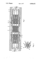
- FIG. 1 is a longitudinal cross section through a plug connection according to the present invention.
- FIG. 2 is an end view of the coupling member of a connector such as that of FIG. 1.
- the connector of the present invention is capable of coupling a fairly large plurality of optical fibers.
- the fibers 2 and 3 are to be coupled to corresponding fibers 22 and 23. It will be recognized that the fibers 22 and 23 are retained in an identical connector to that disclosed in connection to the fibers 2 and 3.
- the two fibers 2 and 3 are taken from the end of a fiber bundle or fiber cable designated as 1.
- the end of the optical fiber cable 1 is secured to a connector housing comprising a connector sleeve 4 and an inner tube 5 using a clamping collet not shown on the figure.
- Within the inner tube 5 of the connector there is installed a guide member 6 containing a plurality of holes 7.
- the holes 7 have a larger diameter on the right-hand side than on the left hand side.
- the diameter of the hole 7 on the left-hand side is just large enough to permit longitudinally movable support of the optical fibers 2 and 3.
- the inner tube 5 and connector sleeve 4 are inserted into a connecting tube 8 which contains a coupling member 9.
- Spring fingers 10 at the circumference of the connector sleeve 4 snap into recesses 11 provided in the connecting tube 8.
- the length of the optical fibers 2 and 3 protruding from the ends of the longitudinal holes 7 prior to insertion of the connector into the connecting tube 8 is such as to be greater than the space provided for them in the connecting member 9.
- the other connector having the fibers 22 and 23 similarly projecting is also inserted within the connecting tube there is insufficient room for the fibers causing them to press against one another and causing at least some of the fibers to be moved backwards sliding within the longitudinal holes 7 and deforming elastically within a space provided for that purpose between the fiber cable 1 and the guide member 6.
- This is illustrated in connection with the fiber 2 which as shown has been bent by its being pushed backward by the fiber 22.
- the end faces of the fibers are pressed together resiliently.
- the end faces of the fiber ends are subjected to surface grinding.
- the length of the tubes within the coupling member 9 should be at least ten times the fiber diameter.
- FIG. 2 shows the end face of a coupling member such as the coupling member 9 of FIG. 1.
- the illustrated coupling member can accept a total of sixteen optical fibers in the sixteen holes 12 provided for that purpose.
- the holes are arranged on two concentric circles and each hole 12 has an end 13 which is either pyramid-shaped or conical shaped in an enlarged fashion to permit easier centering of the optical fibers when the connector is plugged into the connecting tube. This shaping of the ends 13 is also illustrated on FIG. 1.
Landscapes
- Physics & Mathematics (AREA)
- General Physics & Mathematics (AREA)
- Optics & Photonics (AREA)
- Mechanical Coupling Of Light Guides (AREA)
Applications Claiming Priority (2)
| Application Number | Priority Date | Filing Date | Title |
|---|---|---|---|
| DE2334286A DE2334286C3 (de) | 1973-07-05 | 1973-07-05 | Steckverbindung für Lichtleitfasern |
| DT2334286 | 1973-07-05 |
Publications (1)
| Publication Number | Publication Date |
|---|---|
| US4046453A true US4046453A (en) | 1977-09-06 |
Family
ID=5886061
Family Applications (1)
| Application Number | Title | Priority Date | Filing Date |
|---|---|---|---|
| US05/483,515 Expired - Lifetime US4046453A (en) | 1973-07-05 | 1974-06-27 | Plug connection for optical fibers |
Country Status (8)
| Country | Link |
|---|---|
| US (1) | US4046453A (de) |
| AT (1) | AT341803B (de) |
| CH (1) | CH568571A5 (de) |
| DE (1) | DE2334286C3 (de) |
| FR (1) | FR2236197B3 (de) |
| GB (1) | GB1454970A (de) |
| IT (1) | IT1015610B (de) |
| NL (1) | NL7408529A (de) |
Cited By (12)
| Publication number | Priority date | Publication date | Assignee | Title |
|---|---|---|---|---|
| US4135783A (en) * | 1976-05-20 | 1979-01-23 | Siemens Aktiengesellschaft | Device for forming a detachable connection between a waveguide and another optical component |
| US4140365A (en) * | 1976-04-24 | 1979-02-20 | Itt Industries, Inc. | Fiber optic cable connector housing |
| US4265514A (en) * | 1979-06-18 | 1981-05-05 | Gte Laboratories Incorporated | Guide capsule for optical fiber connectors |
| US4330172A (en) * | 1978-08-15 | 1982-05-18 | Bunker Ramo Corporation | Optical fiber connector having transversely mateable plug portions |
| US4367011A (en) * | 1979-05-09 | 1983-01-04 | Bunker Ramo Corporation | Optical fiber connector and means and method for centering optical fibers |
| US4645295A (en) * | 1980-02-04 | 1987-02-24 | Allied Corporation | Fiber optic connector |
| US4726647A (en) * | 1985-03-19 | 1988-02-23 | Sumitomo Electric Industries, Ltd. | Optical connector |
| US4832440A (en) * | 1982-09-01 | 1989-05-23 | Gte Products Corporation | Optical fiber connector |
| US4921324A (en) * | 1982-09-01 | 1990-05-01 | Gte Products Corporation | Optical fiber connector |
| US4964689A (en) * | 1978-11-07 | 1990-10-23 | The United States Of America As Represented By The Secretary Of The Army | Connector for splicing optical fibers |
| US5073045A (en) * | 1991-03-25 | 1991-12-17 | Amp Incorporated | Connector with improved clip connector half |
| US10802239B2 (en) * | 2016-07-07 | 2020-10-13 | Afl Telecommunications Llc | Optical fiber trunk cable breakout canisters and assemblies |
Families Citing this family (6)
| Publication number | Priority date | Publication date | Assignee | Title |
|---|---|---|---|---|
| CA1034804A (en) | 1974-03-20 | 1978-07-18 | Northern Electric Company | Optical fibre connectors |
| DE2527008C3 (de) * | 1975-06-18 | 1981-04-02 | Siemens AG, 1000 Berlin und 8000 München | Mehrfachsteckvorrichtung für Einzellichtwellenleiter |
| US4102561A (en) * | 1975-07-02 | 1978-07-25 | Corning Glass Works | Optical waveguide connector |
| FR2331041A1 (fr) * | 1975-11-05 | 1977-06-03 | Fort Francois | Connecteur pour fibres optiques |
| US4208092A (en) * | 1977-10-14 | 1980-06-17 | Bunker Ramo Corporation | Fiber optic multi-cable pair connector |
| FR2497609B1 (fr) * | 1981-01-07 | 1986-11-21 | Bunker Ramo | Dispositif de connexion du type a pousser-tirer |
Citations (1)
| Publication number | Priority date | Publication date | Assignee | Title |
|---|---|---|---|---|
| US3734594A (en) * | 1972-03-29 | 1973-05-22 | Bell Telephone Labor Inc | Optical fiber connector |
-
1973
- 1973-07-05 DE DE2334286A patent/DE2334286C3/de not_active Expired
-
1974
- 1974-05-31 AT AT453474A patent/AT341803B/de not_active IP Right Cessation
- 1974-06-14 GB GB2658274A patent/GB1454970A/en not_active Expired
- 1974-06-21 CH CH852974A patent/CH568571A5/xx not_active IP Right Cessation
- 1974-06-25 NL NL7408529A patent/NL7408529A/xx not_active Application Discontinuation
- 1974-06-27 US US05/483,515 patent/US4046453A/en not_active Expired - Lifetime
- 1974-07-02 IT IT24703/74A patent/IT1015610B/it active
- 1974-07-03 FR FR7423140A patent/FR2236197B3/fr not_active Expired
Patent Citations (1)
| Publication number | Priority date | Publication date | Assignee | Title |
|---|---|---|---|---|
| US3734594A (en) * | 1972-03-29 | 1973-05-22 | Bell Telephone Labor Inc | Optical fiber connector |
Cited By (12)
| Publication number | Priority date | Publication date | Assignee | Title |
|---|---|---|---|---|
| US4140365A (en) * | 1976-04-24 | 1979-02-20 | Itt Industries, Inc. | Fiber optic cable connector housing |
| US4135783A (en) * | 1976-05-20 | 1979-01-23 | Siemens Aktiengesellschaft | Device for forming a detachable connection between a waveguide and another optical component |
| US4330172A (en) * | 1978-08-15 | 1982-05-18 | Bunker Ramo Corporation | Optical fiber connector having transversely mateable plug portions |
| US4964689A (en) * | 1978-11-07 | 1990-10-23 | The United States Of America As Represented By The Secretary Of The Army | Connector for splicing optical fibers |
| US4367011A (en) * | 1979-05-09 | 1983-01-04 | Bunker Ramo Corporation | Optical fiber connector and means and method for centering optical fibers |
| US4265514A (en) * | 1979-06-18 | 1981-05-05 | Gte Laboratories Incorporated | Guide capsule for optical fiber connectors |
| US4645295A (en) * | 1980-02-04 | 1987-02-24 | Allied Corporation | Fiber optic connector |
| US4832440A (en) * | 1982-09-01 | 1989-05-23 | Gte Products Corporation | Optical fiber connector |
| US4921324A (en) * | 1982-09-01 | 1990-05-01 | Gte Products Corporation | Optical fiber connector |
| US4726647A (en) * | 1985-03-19 | 1988-02-23 | Sumitomo Electric Industries, Ltd. | Optical connector |
| US5073045A (en) * | 1991-03-25 | 1991-12-17 | Amp Incorporated | Connector with improved clip connector half |
| US10802239B2 (en) * | 2016-07-07 | 2020-10-13 | Afl Telecommunications Llc | Optical fiber trunk cable breakout canisters and assemblies |
Also Published As
| Publication number | Publication date |
|---|---|
| ATA453474A (de) | 1977-06-15 |
| IT1015610B (it) | 1977-05-20 |
| DE2334286C3 (de) | 1975-12-04 |
| FR2236197A1 (de) | 1975-01-31 |
| NL7408529A (nl) | 1975-01-07 |
| DE2334286A1 (de) | 1975-01-16 |
| FR2236197B3 (de) | 1977-05-06 |
| CH568571A5 (de) | 1975-10-31 |
| AT341803B (de) | 1978-02-27 |
| GB1454970A (en) | 1976-11-10 |
| DE2334286B2 (de) | 1975-04-24 |
Similar Documents
| Publication | Publication Date | Title |
|---|---|---|
| US4046453A (en) | Plug connection for optical fibers | |
| DE3216560C2 (de) | Steckereinrichtung zum Verbinden zumindest einer Lichtleitfaser mit einem weiteren optischen Element | |
| US4088386A (en) | Optical waveguide connector using resilient material and V-groove | |
| US3963323A (en) | Fiber optic connector with protective cable sleeves | |
| US4193665A (en) | Fiber optic contact alignment device | |
| US3947182A (en) | Fiber optic connector with axial tolerance relief | |
| CA1063398A (en) | Optical waveguide connector | |
| US4127319A (en) | Termination means for fiber optic bundle | |
| US5367595A (en) | Fiber optic connector for connecting a fiber optic harness to an optical device | |
| US6422764B1 (en) | Clamping mechanism for an optical fiber | |
| US5259050A (en) | Multicore optical connector with partitions to separate the optical fibers into groups | |
| US4203650A (en) | Connector for simultaneous end-to-end connection of groups of seven optical fibres | |
| US4312564A (en) | Multi-fiber optic connector | |
| US4146299A (en) | Optical waveguide connectors for multiple waveguide cables | |
| EP0216470A2 (de) | Steckerteil für faseroptisches Kabel | |
| US4110000A (en) | Fiber optic connector | |
| JPS6155646B2 (de) | ||
| US6249635B1 (en) | Universal fiber optic splice holder | |
| GB2057711A (en) | Retaining member for an optical fibre connector | |
| DE2616876C3 (de) | Steckverbindungsanordnung für Lichtwellenleiter | |
| US4422717A (en) | Coupling arrangement for optical waveguides | |
| HU213986B (en) | Switch element for coupling optical fibers | |
| DE2939231A1 (de) | Mehrfachstecker zum anschluss einer glasfaserleitung an einen opto-elektrischen baustein | |
| ES443270A1 (es) | Un conector de cables de fibras opticas mejorado. | |
| EP0034353A3 (en) | Device for the sz-twisting of twisting elements |