US4058676A - Speech analysis and synthesis system - Google Patents
Speech analysis and synthesis system Download PDFInfo
- Publication number
- US4058676A US4058676A US05/593,861 US59386175A US4058676A US 4058676 A US4058676 A US 4058676A US 59386175 A US59386175 A US 59386175A US 4058676 A US4058676 A US 4058676A
- Authority
- US
- United States
- Prior art keywords
- signal
- speech
- voiced
- cepstrum
- parameter
- Prior art date
- Legal status (The legal status is an assumption and is not a legal conclusion. Google has not performed a legal analysis and makes no representation as to the accuracy of the status listed.)
- Expired - Lifetime
Links
- 238000004458 analytical method Methods 0.000 title claims abstract description 123
- 238000003786 synthesis reaction Methods 0.000 title claims abstract description 95
- 230000015572 biosynthetic process Effects 0.000 title claims abstract description 90
- 238000000034 method Methods 0.000 claims abstract description 178
- 238000012545 processing Methods 0.000 claims abstract description 28
- 230000005540 biological transmission Effects 0.000 claims abstract description 24
- 230000003750 conditioning effect Effects 0.000 claims description 56
- 230000001419 dependent effect Effects 0.000 claims description 24
- 230000005284 excitation Effects 0.000 claims description 22
- 230000002194 synthesizing effect Effects 0.000 claims description 20
- 230000015654 memory Effects 0.000 claims description 12
- 230000004044 response Effects 0.000 claims description 12
- 238000005070 sampling Methods 0.000 claims description 12
- 230000000737 periodic effect Effects 0.000 claims description 10
- 238000012544 monitoring process Methods 0.000 claims 8
- 108010076504 Protein Sorting Signals Proteins 0.000 claims 5
- 239000002131 composite material Substances 0.000 claims 3
- 238000007619 statistical method Methods 0.000 abstract 1
- 239000000523 sample Substances 0.000 description 40
- 238000010586 diagram Methods 0.000 description 39
- 230000006870 function Effects 0.000 description 29
- 238000004364 calculation method Methods 0.000 description 22
- 230000008569 process Effects 0.000 description 22
- 230000001755 vocal effect Effects 0.000 description 10
- 238000010606 normalization Methods 0.000 description 9
- 238000003066 decision tree Methods 0.000 description 8
- 210000001260 vocal cord Anatomy 0.000 description 6
- 239000011159 matrix material Substances 0.000 description 5
- 238000007906 compression Methods 0.000 description 4
- 238000001514 detection method Methods 0.000 description 4
- 230000008901 benefit Effects 0.000 description 3
- 230000006835 compression Effects 0.000 description 3
- 230000006872 improvement Effects 0.000 description 3
- 230000009467 reduction Effects 0.000 description 3
- 238000012360 testing method Methods 0.000 description 3
- 238000007792 addition Methods 0.000 description 2
- 239000000872 buffer Substances 0.000 description 2
- 230000015556 catabolic process Effects 0.000 description 2
- 230000008859 change Effects 0.000 description 2
- 238000004891 communication Methods 0.000 description 2
- 238000013144 data compression Methods 0.000 description 2
- 230000007423 decrease Effects 0.000 description 2
- 238000006731 degradation reaction Methods 0.000 description 2
- 230000008520 organization Effects 0.000 description 2
- 238000007781 pre-processing Methods 0.000 description 2
- 238000005549 size reduction Methods 0.000 description 2
- 241000282461 Canis lupus Species 0.000 description 1
- 239000000654 additive Substances 0.000 description 1
- 230000000996 additive effect Effects 0.000 description 1
- 230000001143 conditioned effect Effects 0.000 description 1
- 230000006837 decompression Effects 0.000 description 1
- 238000013461 design Methods 0.000 description 1
- 238000011161 development Methods 0.000 description 1
- PCHJSUWPFVWCPO-UHFFFAOYSA-N gold Chemical compound [Au] PCHJSUWPFVWCPO-UHFFFAOYSA-N 0.000 description 1
- 239000010931 gold Substances 0.000 description 1
- 229910052737 gold Inorganic materials 0.000 description 1
- 238000012432 intermediate storage Methods 0.000 description 1
- 238000005259 measurement Methods 0.000 description 1
- 230000003534 oscillatory effect Effects 0.000 description 1
- 230000008447 perception Effects 0.000 description 1
- 230000000063 preceeding effect Effects 0.000 description 1
- 238000000926 separation method Methods 0.000 description 1
- 238000007493 shaping process Methods 0.000 description 1
- 238000010183 spectrum analysis Methods 0.000 description 1
- 238000012546 transfer Methods 0.000 description 1
- 238000005303 weighing Methods 0.000 description 1
Images




Classifications
-
- G—PHYSICS
- G10—MUSICAL INSTRUMENTS; ACOUSTICS
- G10L—SPEECH ANALYSIS TECHNIQUES OR SPEECH SYNTHESIS; SPEECH RECOGNITION; SPEECH OR VOICE PROCESSING TECHNIQUES; SPEECH OR AUDIO CODING OR DECODING
- G10L19/00—Speech or audio signals analysis-synthesis techniques for redundancy reduction, e.g. in vocoders; Coding or decoding of speech or audio signals, using source filter models or psychoacoustic analysis
- G10L19/04—Speech or audio signals analysis-synthesis techniques for redundancy reduction, e.g. in vocoders; Coding or decoding of speech or audio signals, using source filter models or psychoacoustic analysis using predictive techniques
- G10L19/06—Determination or coding of the spectral characteristics, e.g. of the short-term prediction coefficients
-
- H—ELECTRICITY
- H04—ELECTRIC COMMUNICATION TECHNIQUE
- H04B—TRANSMISSION
- H04B1/00—Details of transmission systems, not covered by a single one of groups H04B3/00 - H04B13/00; Details of transmission systems not characterised by the medium used for transmission
- H04B1/66—Details of transmission systems, not covered by a single one of groups H04B3/00 - H04B13/00; Details of transmission systems not characterised by the medium used for transmission for reducing bandwidth of signals; for improving efficiency of transmission
Definitions
- the present invention relates generally to speech analysis and synthesis systems and, more particularly, to systems designed to operate in real time for combining a plurality of telephone channels into a single telephone channel for further transmission and subsequent separation of the channels and synthesizing the speech waves from abbreviated speech data.
- control parameters are used in a subsequent speech synthesizer which also is an electrical analog of the human vocal cords and tract which produced the original speech sounds.
- the electrical output of the synthesizer is applied to a suitable transducer to produce the audible speech sounds.
- the analysis synthesis was practically useable only for special transmission mediums with relatively wide band widths.
- Utilization of the analysis synthesis technique for a single channel telephone line offered no particular advantages except for the fact that the transmitted speech data was difficult to decode without knowing the analysis and synthesis process itself.
- the speech analysis and synthesis system of the present invention provides a plurality of novel signal processing techniques which permits the substantially parallel analysis and synthesis of a pluraltiy of voice channels with the speech data from the plurality of channels being time-division multiplexed for transmission through a single transmission media.
- a presently preferred embodiment of the system of the invention permits analyzing speech data from four telephone channels and transmitting the multiplexed speech data through a single telephone channel which is normally capable of transmitting sufficient information for only one speech channel. It should be noted, however, that, in addition to well known limitations due to bandwidth and coding techniques, the number of channels which may be processed is also presently limited by the processing speed of presently available hardware.
- a plurality of digital signal processing techniques incorporated into the system of the invention sufficiently reduce the processing time for each channel so that four simultaneous speech channels may be analyzed and time-division multiplexed into a single channel, transmitted to a receiving de-multiplexer and the speech signals synthesized from the received speech data in "real time.”
- the analysis techniques also generate speech data which is sufficiently accurate and representitive of the speech signals so that the synthesized speech signals are practically indistinguishable from the original speech signals.
- the speakers at either end of a particular circuit may be unaware of the intermediate analysis and synthesis process.
- the system of the invention provides a single channel analyzer synthesizer combination in which the analyzer provides the control parameters of pitch period, a voiced/unvoiced decision parameter, linear prediction coefficient parameters and a power parameter which are used to control the synthesizer to generate pitch pulses or random noise in accordance with the pitch period parameter and voiced/unvoiced decision parameter.
- the pulses or noise are gain controlled by the power parameter and applied to a filter controlled by the coefficient parameters and the output is the reconstructed speech.
- the basic single channel system may be expanded to handle a plurality of channels substantially in parallel by sequential time-division multiplexing the various signal processing steps of the complete system.
- the generated control parameters for each channel are multiplexed for transmission to the synthesizer where the processing is reversed to produce speech signals for the plurality of channels.
- a logarithm signal must be generated from a previous signal.
- the data signals are so conditioned and weighted that a linear signal approximation of the logarithm may be generated, at considerable savings in signal processing time, without appreciable error in the subsequent calculations.
- system of the invention contains some entirely new analysis procedures which greatly enhance the speed and accuracy of the signal processing to produce an integrated system capable of "real time” analysis and synthesis of a plurality of speech or data communications channels.
- the basic analysis of the Cepstrum signal produces, by determination of the time position of the highest pitch pulse, a basic pitch period. It is a feature of the present invention to interpolate a more accurate pitch period by an interpolation procedure using the amplitudes of the basic pitch period pulse and the immediately preceeding and following pulses and the basic pitch period. The result is a more accurate pitch period parameter.
- Another feature of the present invention is generation of a more accurate voiced/unvoiced decision parameter by a sequential examination, in a definite priority, of a plurality of generated auxilliary signals based on the configuration of the Cepstrum signal and additional signals present in the system as the result of the analysis of the speech signals for other control parameters.
- the resultant voiced/unvoiced decision parameter is much more likely to be correct than when only one parameter is examined.
- a further feature of the present invention is a technique for more practically relating system noise to such things as, for example, the voiced/unvoiced decision where a high noise level could result in an unvoiced decision when the speech signal is actually voiced.
- the average noise is estimated from a consideration of the first auto-correlation coefficient parameters descriptive of the vocal tract described above.
- the first autocorrelation coefficient generally represents the average power in the speech signal at any given instant and the estimated noise is never allowed to rise above that signal but when the coefficient periodically rises during voiced speech segments, the estimated noise signal can only rise toward that coefficient at a predetermined rate.
- the estimated noise signal tends to follow the lowest values of the first auto-correlation coefficient during unvoiced speech segments.
- Another feature of the invention is the utilization of a reduced length of "limited" frame of speech data in the determination of the coefficient parameters. It has been found that the size reduction does not appreciably affect the accuracy of the generation of the coefficients and results in a further increased savings in processing time.
- the size reduction is accomplished through the initial windowing needed for the speech data prior to calculation of the coefficients.
- the limited window has all of the prerequisite signal shaping capabilities but operates only over the center portion of the data frame.
- a further feature of the system of the invention is a voice synthesizer excitation function which differs from the typically rectangular pulse applied to the synthesizer filter.
- the voice synthesizer excitation function is generally an amplitude increasing periodic waveform which, when applied to the synthesizer filter, produces a more natural sounding synthetic speech without the usual "buzzing" sound produced at low frequencies by more conventional synthesizers.
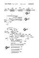
- FIG. 1 is a block diagram of the analysis section of the speech analysis synthesis system of the invention
- FIG. 2 is a block diagram of the synthesis section of the invention
- FIG. 3 is a block diagram of a basic speech synthesizer
- FIG. 3a is a block diagram of an analyzer for one channel of the analyzing portion of the invention shown in FIG. 1;
- FIG. 3b is a block diagram of a synthesizer for a single channel for the synthesizer portion of the system shown in FIG. 2;
- FIG. 4 is a block diagram of the normalization calculation section of the synthesizer shown in FIG. 3;
- FIG. 5 is a block diagram of the Cepstrum Weighting section of the analyzer shown in FIG. 3;
- FIG. 6 is a wave-form diagram of a Cepstrum as modified by the Cepstrum Weighting section as shown in FIG. 5;
- FIG. 7 is a simplified block diagram of a Cepstrum generator section of the analyzer shown in FIG. 3a;
- FIG. 8 is a graph illustrating the linear log approximation technique of the invention.
- FIG. 9 is a block diagram of a method of implementing the linear log approximation technique.
- FIG. 10 is a graphical illustration of the data processing sequence for the linear log approximation technique
- FIG. 11 is a wave-form signal diagram of a Cepstrum and related samples as used in the pitch interpolation section of the analyzer shown in FIG. 3;
- FIG. 12 is a hardware function block diagram of the pitch interpolation technique of the invention.
- FIG. 13 is a hardware function block diagram of the pitch detector section of the analyzer shown in FIG. 3;
- FIG. 14 is a hardware function block diagram of the Cepstrum factors generator section of the analyzer of FIG. 3;
- FIG. 15 is a hardware function block diagram of the voiced/unvoiced decision section of the analyzer of FIG. 3;
- FIG. 16 is a signal diagram of the variation of the power term (R.sub. ⁇ ) and its relationship into the generated estimated noise term (EST);
- FIG. 17 is a hardware function block diagram of the estimate generator section of the analyzer of FIG. 3 with a companion test for an initial voiced/unvoiced decision;
- FIG. 18 is a signal diagram of a sampled speech wave
- FIG. 19 is a signal diagram of the samples as passed by the limited window section of the analyzer of FIG. 3;
- FIG. 20 is a hardware function block diagram of the limited window section of FIG. 3;
- FIG. 21 is a signal diagram of a conventionally generated pitch pulse for use in a synthesizer section of the invention.
- FIG. 22 is a signal diagram of a modified pitch pulse according to the invention.
- FIG. 23 is a signal diagram of the modified pitch pulse of the invention as generated by the pitch/noise generator section of the synthesizer shown in FIG. 3b;
- FIG. 24 is a hardware function block diagram of the pitch pulse generator of the pitch/noise generator section of the synthesizer shown in FIG. 3b.
- the speech analysis and synthesis system of the present invention has for its basic purpose a reduction of data necessary to transmit speech electronically through a relatively limited bandwidth medium, such as a voice grade telephone line.
- the reduction is such that, for the described presently preferred embodiment of the invention, four separate speech channels may be transmitted through the single telephone channel which was originally designed for only one speech channel.
- the described analysis-synthesis process is sufficiently accurate so that there is substantially no noticeable degradation in the quality of any of the four received speech channels.
- the analysis-synthesis system of the invention operates on the known principle that a speech waveform, whether oral or its electrical analog, is dependent on the vocal cords and the associated physical vocal tract which creates it.
- the basic speech analysis-synthesis technique is to assume an analyzable vocal tract with a predetermined number of control parameters and to determine, substantially by mathematical analysis, what the value of those control parameters are for prescribed length of speech time or a "frame time.”
- the control parameters may then be transmitted in abbreviated form, as in the present invention, for example, to a synthesizer which is a mechanical or electrical analog of the vocal tract under the control of the selected parameters.
- the synthesizer substantially reproduces the original speech waveform.
- the parameters are subjected to data compression by a circuit which operates to examine each set of parameters, relating to each "frame time,” and to eliminate redundancy or non-changing information from frame to frame.
- the speech analysis and synthesis system of the present invention employs a linear prediction analysis method in which the representative parameters are pitch period, voiced/unvoiced decision, power and ten "K" coefficients descriptive of the analytical vocal tract which produced the speech.
- the speech signal to be analyzed in the presently preferred embodiment of the invention is of voice grade telephone channel quality which is of considerably restricted band width, approximately 300-3000 Hz. It should be appreciated that conventional analysis techniques have available as the speech signal the entire band width produced by an individual speaker while the speech signal available for analysis with the system of the present invention is severely restricted in band width and, for example, the basic pitch frequency typically may not be contained within the range of available frequencies so that pitch must be determined from an analysis of the harmonic frequency content present within the available band width.
- the speech analysis and synthesis system of the present invention receives input speech signals from four input channels on lines 100-106 which are typically voice grade telephone lines.
- an analog to digital converter 108 operating substantially in parallel, by rapid time multiplexer operations on each channel, converts the analog signals on the input lines 100-106 to corresponding digital channel signal information.
- the digital channel information is fed through lines 110-16 to an analyzer 118 which performs the analysis of the four channel information, again substantially in parallel.
- the analysis process will be discussed in detail below.
- the analyzer 118 produces the parameters discussed above which are fed through lines 120-126 to a compression circuit 128 which essentially analyzes the frame data of each channel on a frame to frame basis to eliminate redundant or non-changing information from frame to frame.
- the compression process is also performed substantially in parallel for each of the channels and the particular techniques employed are disclosed in copending application Ser. No. 596,832 entitled DATA COMPRESSION SYSTEM.
- the compressed data output is fed through lines 130-136 to a four channel multiplexer 138 which time-division multiplexes the compressed channel data into a single serial data stream on a line 140 which feeds a MODEM 142 which produces a digital signal pattern suitable for transmission through a conventional voice grade telephone line.
- the digital signal on an output line 144 is fed into a digital-to-analog converter 146 which converts the digital signal into an actual analog signal which is then fed over an output line 148 to a conventional voice grade telephone line.
- an input from a voice grade telephone line on an input line 150 is fed to an analog-to-digital converter 152 which digitizes the signal which is then fed through a line 154 to a digital Modem 156 which recovers the time-division multiplexed digital channel parameter data.
- the digital data is fed through a line 158 to a demultiplexer 160 which separates the digital channel parameter data into four separate channels on lines 162-168 connected to a decompression circuit 170 which analyzes the parameter data on all four channels substantially in parallel to generate complete sequential parameter data for each channel which is then fed through lines 172 through 178 to a synthesizer 180.
- the synthesizer 180 would take the form shown in FIG. 3 in which a pitch pulse generator 199a generates pitch pulses in accordance with the received pitch period parameter on line 199b.
- a random noise generator 199c produces a noise signal for use with unvoiced speech signals.
- the outputs of the pitch pulse generator 199a and random noise generator 199c are connected to respective pole terminals of a single pole-double throw switch 199d which is under the control of the voiced/unvoiced decision parameter to connect the output of the pitch pulse generator 199a to the remainder of the circuit if the decision is voiced or connect the output of the random noise generator 199d to the circuitry of the decision is unvoiced.
- the output of the switch 199d is connected through a gain control 199e, under the control of the power parameter, to the input of a filter 199f whose characteristics are under the control of the coefficients connected to the filter through the lines 199g.
- the output of the filter 199f is connected through line 199h to the remainder of the circuitry.
- the synthesizer 180 of the present invention synthesizes the original human vocal tract from the channel parameters on the lines 172-178 substantially in parallel to produce digital representations of the speech signals on lines 182-188.
- the digitized speech signals on lines 182-188 are fed to a digital-to-analog converter 190 which converts the signals to analog form substantially in parallel and produces an output on lines 192-198 suitable for further transmission to four separate voice grade telephone lines connected to conventional telephone sets (not shown), for example.
- FIG. 3a is a hardware function block diagram of an analyzer for a single channel. It should be appreciated that each step of the analysis for the single channel is also performed substantially in parallel by utilizing appropriate buffers and other intermediate storage devices which are well known and conventional in the art.
- the digital speech input on a line 200 is analyzed to produce the pitch period, power and coefficient (K's) parameters on lines 202, 204 and 206 respectively.
- the voiced/unvoiced decision parameter is represented by setting the pitch period parameter to zero.
- the analysis process is essentially three separate analysis steps. The first analysis step is to determine the pitch period of the digital speech input. The second analysis step is the determination of the coefficients (K's) of the analytical vocal tract which produced the digital speech input and the third analysis step is to determine whether the frame of digital speech input data is voiced or unvoiced which, as described above, determines whether a pitch frequency or random noise is applied to the filter 199f in the synthesizer shown in FIG. 3.
- each of the pitch period analysis and coefficient determination steps require only portions of that complete speech signal data. Therefore the speech signal data is modified as it proceeds through the various analysis steps.
- the digital speech input is applied first to a conventional low pass filter 208 to eliminate extraneous high frequency components which are out of the analytical band.
- the low pass filter 208 is digital in nature and is conventionally constructed in accordance with well known techniques such as that discussed in "Digital Processing of Signals,” Gold and Rader, McGraw-Hill, 1969 to produce alternate samples at its output on line 210.
- the output of the low pass filter on line 210 is connected to a normalization calculation circuit 212 in order to normalize the amplitudes of the samples of digital speech data to a particular value upon which the further analysis is based.
- the normalized digital speech data on output line 214 is connected to a Fast Fourier Transform (FFT) window 216.
- FFT Fast Fourier Transform
- the particular class of window is utilized because the Cesptrum calculation is a Fast Fourier Transform process and the FFT window 216 ensures maximum effectiveness of the Cepstrum calculation.
- the window data on line 218 is connected to a conventional Cepstrum generator 220 which performs the Cepstrum calculations, as discussed above.
- Cepstrum calculation uses conventional sequential processing techniques
- a feature of the system of the invention is that only alternate samples of the digital speech data are used in the Cepstrum calculation in order to decrease the processing time necessary to generate the Cepstrum. It has been found that any degradation in the generation of the Cepstrum is minimal and the accuracy of the subsequent pitch determination from the Cepstrum can be partially restored in a novel pitch interpolation technique which is described in detail below.
- the Cepstrum data on output line 222 is utilized not only in the determination of pitch but in the latter determination of the voiced/unvoiced decision, as discussed below.
- the Cepstrum data is connected to a Cepstrum weighting section 224, described in detail below, which modifies the Cepstrum waveform in order to enhance the detection of the Cepstrum peak values needed to determine pitch.
- the weighted Cepstrum on output line 226 is connected to a pitch detector 228 which scans the weighted Cepstrum for peak values and checks the original peak determination for the "double pitch” phenomenon described in the literature. See Noll, "Cepstrum Pitch Determination," The Journal of the Acoustical Society of America, Vol. 44, No. 2, 1967, p.293.
- the pitch or pitch number generated by the pitch detector 228 is then connected through a line 230 to a pitch interpolation section 232 which examines the pitch data and surrounding Cepstrum data to interpolate between sample values in the vicinity of the detected pitch period and, by a mathematical interpolation technique, generates a more accurate peak value and pitch period.
- the pitch interpolation section 232 partially restores the accuracy of the pitch period even though only alternate Cepstrum data samples were utilized, as discussed above.
- the interpolated pitch period value on output line 234 is connected through a gate 236 to the output line 202 for the pitch period.
- the interpolated pitch period value on line 234 designated the pitch period on line 202.
- the pitch period on output line 202 is set to zero to indicate the unvoiced condition.
- the voiced/unvoiced decision determines whether the calculated pitch period value is to be utilized or not. It should be appreciated that the pitch determining calculation may result in the generation of a pitch number despite the fact that the other parameters of the digital speech data on line 200 indicate that the data represents unvoiced speech.
- the full analysis of the digital speech input determines the voiced/unvoiced decision and, if it is voiced, the output of the pitch interpolation section 232 is deemed to be correct pitch period value.
- the digital speech data on line 200 is subjected to a different analysis process.
- the data on line 200 is connected first to a novel limited window 238 which conditions the data for the calculation of the coefficients.
- the limited window 238 takes advantage of the empirically determined fact that, for the coefficient calculations, the digital speech data located at either end of the window can be effectively deleted, limiting the number of samples of the digital speech data needed for the calculations.
- the limited window 238 provides a properly windowed abbreviated frame of data for the coefficient calculations.
- the truncated and windowed digital data on line 240 is then subjected to a conventional and well known linear prediction analysis and, therefore, is connected to a conventional autocorrelator 242 which generates intermediate autocorrelation coefficients on output line 244 further connected to a matrix solution section 246 which generates the K coefficients on line 206, a power term on line 204 and an error term (DAA) on a line 248 which is subsequently used in the voiced/unvoiced decision, as will be discussed below.
- a conventional autocorrelator 242 which generates intermediate autocorrelation coefficients on output line 244 further connected to a matrix solution section 246 which generates the K coefficients on line 206, a power term on line 204 and an error term (DAA) on a line 248 which is subsequently used in the voiced/unvoiced decision, as will be discussed below.
- DAA error term
- the autocorrelator 242 and matrix solution section 246 are constructed in accordance with conventional design techniques for a linear prediction solution such as discussed in Makhoulaad Wolf, "Linear Prediction and the Spectral Analysis of Speech," NTIS, AD-749066, Bolt, Beranek and Neuman, Inc., Cambridge, Mass., RBN Rep. 2304, Aug. 1972. See also U.S. Pat. Nos. 3,624,302 and 3,631,520.
- the error term DAA is a conventional output of the least mean squares analysis of the matrix solution and is well known though it may not be utilized in systems of the prior art.
- the third analysis technique is making the voiced/unvoiced decision.
- a plurality of factors are examined in a particular order of priority and, a superior factor decision is deemed determinative of the voiced/unvoiced decision.
- the examination of a factor may not result in a decision in which case the following factor is examined.
- a particular factor determines that the digital speech input is representative of unvoiced speech
- the remaining inferior factors are not considered.
- each of the factors are variable, and a voiced/unvoiced decision is dependent upon the factor falling outside of an "ambiguous range.” If the factor value is within the ambiguous range the other factors are sequentially examined to determine whether or not they also fall within their individual ambiguous ranges.
- the voiced/unvoiced decision can be made. But when all the factors are within their ambiguous ranges, the decision is to use the pitch number generated on line 234 as that appears to be the best use of all the analytical data.
- the overall signal represented by the digital speech data is sufficiently "organized" so as to have resulted from definite pitch pulses generated by the vocal cords.
- this organization is determined by comparing a parameter which is dependent upon organization of the signal with the average noise contained by the signal. If the dependent parameter is not sufficiently greater than the average noise level, the decision is immediately made that the digital speech data on line 200 must be unvoiced.
- the dependent parameter which is used is the first autocorrelation coefficient (R.sub. ⁇ ) generated by the autocorrelator 242.
- the average estimated noise in the digital speech data is produced by an estimate generator 252.
- the average noise signal "EST" produced by the estimate generator on line 254 is compared with the first autocorrelation coefficient R.sub. ⁇ to determine whether the unvoiced decision may be made immediately.
- the operation of the estimate generator 252 is described in detail below.
- the estimated noise signal EST on line 254 is multiplied by the constant 2 on line 257 by multiplier 256 and the doubled estimate signal on line 258 is compared with the first autocorrelation coefficient signal R.sub. ⁇ on line 250 by means of a comparator 260.
- the comparator 260 produces an output which is an unvoiced decision if R.sub. ⁇ is less then twice the estimated noise signal.
- the output on line 262 is connected to one input of an OR gate 264 the output of which on line 265 controls the gate 236 which either passes the interpolated pitch number on line 234 to the pitch number output line 202 or sets the pitch number on line 202 to zero if the unvoiced decision is made.
- the fact that the first autocorrelation coefficient R.sub. ⁇ is greater than twice the estimated noise level is not determinative that the digital speech data is voiced.
- a further, more analytical decision is then made by examining the plurality of factors described above. The most important factors to be examined are those derived from an examination of the Cepstrum signal on line 222 as well as the detected pitch on line 230. Both signals are connected to the input of a Cepstrum factors generator 266 which produces three auxilliary signals which will be discussed in detail below.
- the "R peak,” “A peak,” and “C peak” signals on lines 268, 270 and 272, respectively, result from an examination of the sharpness of the peak of the Cepstrum and the further information contained in the Cepstrum waveform.
- the signals on lines 268, 270 and 272 are connected as inputs in a prescribed priority to a voiced/unvoiced decision tree 274.
- the voiced/unvoiced decision tree 274 essentially examines the signals on the lines 268-272 to determine whether they fall within accepted ranges. If any of the signals fall outside of a particular range, the decision is made that the digital speech data is voiced or unvoiced. If a particular factor signal falls within the prescribed range, the decision is indeterminate and the next factor signal is examined.
- the digital speech data on line 200 is examined by means of a zero-crossing detector 276 to determine how many times the signal crosses the zero axis.
- the number of zero-crossings as an output on line 278 is applied to the voiced/unvoiced decision tree 274 and, again, if the number of zero-crossings falls within a prescribed range, the voiced/unvoiced decision can be made.
- an error signal DAA on line 248 from the matrix solution block 246 is examined to determine how random the digital speech input signal is.
- the matrix solution 246 is essentially a least mean squares approximation and, if the approximation is reasonably close to a periodic signal, the error signal DAA will be low indicating a voiced decision however, if the digital speech data is substantially random, the error signal DAA on line 248 will be relatively high, indicating an unvoiced condition.
- the voiced/unvoiced decision tree 274 produces an output on a line 284 only for an unvoiced decision which is connected as a second input to OR gate 264 which again, through output line 265 controls the gate 236. If a voiced decision from the voiced/unvoiced decision tree 274 is made, the output line 284 is automatically set to a no output condition. Thus, the unvoiced condition is indicated by an output on line 262 or 284.
- the pitch period, power and K speech parameters on lines 202, 204 and 206 of the analyzer illustrated in FIG. 3 represent the digital control parameters for one frame of digital speech data for one channel of the complete system illustrated in FIG. 1.
- the frame parameters for each channel are analyzed further in a compression section 128 and thereafter time-division multiplexed and changed into a signal form suitable for transmission over a voice grade telephone line.
- the digital speech parameters are recovered and, one frame at a time, applied to a synthesizer 180 which operates on one channel at at time but which essentially synthesizes all four channels in parallel.
- the synthesis process which occurs for each frame for each channel is illustrated in FIG. 3b.
- the recovered pitch period, power and K parameters are connected as inputs to the synthesizer on lines 286, 288 and 290, respectively.
- the pitch period, power and K parameters on line 286, 288 and 290 are interpolated by means of a pitch interpolator 292, a power interpolator 294 and a K interpolator 296.
- the interpolators 292, 294 and 296 merely insure that there are no abrupt changes in any of these parameters which would introduce unnatural distortions in the synthesized speech.
- the outputs of the pitch interpolator 292 and power interpolator 294 are connected through lines 298 and 300, respectively, to a pitch/noise generator 302 which produces at its output line 304 a digital signal representing pitch pulses at a particular frequency or, if the pitch number is zero, indicating unvoiced speech, a random noise generator is activated to produce random noise signals.
- the amplitude or level of the pitch pulses or random noise is controlled by the power signal on line 300.
- the K.sub. ⁇ through K.sub. ⁇ parameters on an output line 306 of the K interpolator 296 are applied as control inputs to a lattice filter 308 which, in digital form simulates the physical vocal tract of the original human speaker.
- the pitch pulses or random noise on line 304 are applied to the lattice filter 308 are under the control of the K parameters, producing a digital speech signal on an output line 310 for one channel which is substantially a duplicate of the original speech input in digital form.
- the digital speech signals on lines 182-188 are applied to the digital to analog coverter 190 and the analog signals are applied to the four output channels which are themselves voice grade telephone lines to conventional telephone sets (not shown).
- the pitch/noise generator 302 of the synthesizer shown in FIG. 3b is of novel form as will be discussed below and utilizes a novel pitch pulse technique which more closely approximates the waveform of the physical vocal cords, at least as communicated through a telephone line.
- the digital speech signal output on line 310 is a very close approximation of the original speech input. Indeed, the approximation or synthesis is sufficiently accurate that, within the band width confines of a telephone channel, the fact that the original speech has been electronically processed is substantially undetectable.
- the determination of pitch includes preprocessing the digital speech input on line 200 of FIG. 3a to optimize the analysis process.
- Part of the preprocessing of the digital speech input is normalizing the particular digital speech input to a particular or maximum amplitude by means of a normalization block 212.
- the normalization calculation is effected by means of a technique illustrated in FIG. 4.
- the maximum numerical value for the purpose of normalization is set at 0.5 (decimal). It should be appreciated however, that any numeric value (M) which is equal to or less than 0.5 may be utilized in the normalization technique illustrated in FIG. 4.
- the digital speech data on line 210 is generally considered to be a series of ordered samples which, for the purposes of the following discussion, may take the form illustrated in the sequence in Equation 1 below,
- S.sub. ⁇ is arbitrarily defined as the maximum numeric, or "peak” value.
- the digital speech sample data on line 210 is serially shifted into a sample register 312 until all of the samples are in the register.
- each sample is examined by a peak detector 314 which, through control line 316, enables the transfer of the peak amplitude value to a peak register 318.
- the peak register 318 contains the sample S.sub. ⁇ .
- the sample value in the peak register 318 is connected through a line 320 to one input of a comparator 322 which compares the peak value with a constant 0.5, used in the presently preferred embodiment connected on a line 324 to the second input of the comparator. If the peak value in the peak register 318 is less than 0.5, the comparator 322 activates a high speed shift clock 326 through a line 328. High speed shift clock pulses on an output line 330 of the high speed shift clock 326 are applied to the parallel shift input of the sample register 312 and to the parallel shift input of the peak register 318. All of the samples are simultaneously shifted at high speed toward greater values until the maximum value or peak sample in the peak register 318 is greater than 0.5. Assuming that N shifts are necessary to reach that value, the samples will be in the form of Equation 2, or:
- the then peak value 2 N S.sub. ⁇ in the peak register 318 is connected through a line 320 to a reciprocal taking or divide block 332 which takes the reciprocal of NS.sub. ⁇ in the only divide operation necessary for the complete normalizaion calculation procedure.
- the reciprocal 1/2 N S.sub. ⁇ on an output line 334 of the reciprocal taking block 332 is connected as an input to a multiplier 336 which has a second input on line 324 of the constant 0.5.
- the output of the multiplier on line 338 is therefore 0.5/2 N S.sub. ⁇ which then becomes a constant factor which serves as one input to a second multiplier 340.
- Each sample in the sample register 312 is then serially shifted out on a line 342 to a second input to the multiplier 340 and each sample is multiplied by the constant factor 0.5/2 N S.sub. ⁇ .
- a serial output on a line 344 may be shifted into a buffer 346 for further outputing on line 214 to the window 216 shown in FIG. 3a.
- the output of the multiplier 340 on line 344 is the general form: ##EQU1## so that the peak value is 0.5 and the values of all the other samples are normalized to that peak value.
- the output of the Cepstrum generator 220 of FIG. 3 is considered to be a conventional Cepstrum (See Noll, supra) having a main or primary peak followed by one or more secondary peaks along the time or t axis.
- a conventional Cepstrum See Noll, supra
- the position of the primary and secondary peaks must be determined. Since increasing values of t are affected by the window and low pass filter and reduced in amplitude, the Cepstrum signal is weighted in accordance with the present invention in the Cepstrum weighing section 224 which is illustrated in more detail in FIGS. 5 and 6.
- the Cepstrum signal waveform 347 is applied to a modified or skewed t' axis 348 while a threshold voltage level 350 remains parallel to the convention t axis 352. It can be seen that the primary peak 354 is well above the threshold level 350 and is immediately detectable. In general it will also be seen that a secondary peak 356 is above the threshold level because of the inclined t' axis 348.
- the technique for implementing the Cepstrum weighting process is illustrated by the hardware function block diagram shown in FIG. 5.
- the sequential digital Cepstrum samples are applied as an input on line 222 to a sample AND gate 360.
- the Cepstrum samples are then connected through line 362 to one input of an adder 364.
- the second input to the adder 364 on line 368 is a linearly increasing function generated in the following manner.
- An increment constant I which, for the presently preferred embodiment may be 1/512, is applied on a line 370 to one input of a second AND gate 372.
- the constant I on line 370 and the sequential Cepstrum samples on 358 are both simultaneously gated by means of an enabling line 374 generated by a sample clock 376 so that the Cepstrum sample and the constant are simultaneously applied to the remainder of the circuitry.
- the constant I gated through AND gate 372 is applied through an output line 378 to one input of a second adder 380 which, together with a register 382 form a digital integrator.
- the output of the register 382 on line 368 is connected both to the Cepstrum adder 364 and as a second input to the second adder 380.
- the output of the adder 380 on line 384 is essentially the product of the constant I times the number of successive additions which have been performed for the number of sequential Cepstrum samples for a particular data frame.
- the output of the adder 364 on line 226 is the sum of the present Cepstrum sample and present value of the number of times the constant has been added to itself.
- a conventionally generated frame clock signal on a reset line 286 is applied to the register 382 to reset the time-increasing Cepstrum weighting function.
- the conventional analysis sequence is illustrated in FIG. 7 in which the windowed digital speech data on line 218 is first applied to a Fourier Transform generator 388.
- the digital transform data on an output line 390 is then applied to a logarithm generator 392 which generates a logarithmic signal, to the base 2, which is further connected through line 394 to a second Fourier Transform generator 396, the output of which is the Cepstrum data on line 222.
- the logarithm to the base 2 of a particular number (N) is derived by means of a linear piece-wise approximation technique which is illustrated in FIG. 8.
- the output of the Fourier Transform generator 388 is shifted and constrained to be a number between 0.5 and 1.0. Over that range, a straight line defined by the equation,
- any number N is shifted to the left a sufficient number of times so that the remaining new N is between 0.5 and 1.0.
- the number of shifts necessary to produce a new N within that range is the characteristic of the logarithm to the base 2.
- the linear logarithm technique of the invention is implemented in accordance with the hardware function block diagram illustrated in FIG. 9.
- the number N on a input line 392 is loaded in parallel into a shift register 394 by means of a load and clear signal on line 396 connected to the load input of a conventional shift register and the clear input of a characteristic counter 398.
- the number N in the shift register then may appear as in the data diagram 400 shown in FIG. 10.
- the number is then shifted to the left until the absolute value of that number is greater than 0.5 which is determined by the position to the immediate right of the binary point being a "1" as illustrated by the data diagram 402 in FIG. 10.
- the one bit is detected by the most significant bit line 408 connected to a sign detector 410 which has an output line 412 which controls a gate 414. While the number N was being shifted to the left by means of a shift left clock signal on a control line 416, the shift clock pulses were transferred through gate 414 to a characteristic counter 398. Thus, the number of left shift clock pulses needed to shift the number to the format of the data diagram 402 shown in FIG. 10 is the characteristic of the logarithm.
- the shifted number in the shift register 394 is then gated in parallel through a line 416 to an adder 418 which has as a second input the constant "-1" on input line 420.
- the output of the adder on line 422 has the format of the data diagram 404 shown in FIG. 10.
- the difference number on line 422 is shifted to the left by a shift one register 424 which effectively multiplies the number by 2 to produce a data diagram 406 shown in FIG. 10.
- the output of the shift one register 424 on line 426 is the mantisa of the logarithm to the base 2 and forms one input to an adder 428.
- the second added input on line 430 to the adder 428 is the characteristic of the logarithm stored in the characteristic counter 398.
- the output of the adder on line 432 is the sum of the characteristic and mantisa which is the logarithm to the base 2 of the number N according to the linear piece-wise approximation technique of the invention.
- the output of the pitch detector 228 in FIG. 3 is basically a number defining the position of a peak amplitude along the Cepstrum axis.
- the pitch detection technique is based on utilizing only alternate samples of the Cepstrum to reduce processing time. While the pitch numbers generated are sufficiently accurate for many applications, in order to restore additional pitch accuracy, the pitch interpolation technique of the present invention is utilized to substantially examine the intermediate samples of the Cepstrum to determine if such an intermediate sample may more accurately represent the true pitch.
- the interpolation technique is illustrated in FIGS.
- the present invention utilizes a substantially parabolic interpolation between the chosen peak b and the sample values a and c on either side of the chosen sample.
- the interpolation technique is utilized to calculate the difference ⁇ x between x.sub. ⁇ the pitch number of the chosen peak sample b and the true pitch number x p . It can be shown that,
- the pitch interpolation technique is implemented by the hardware function block diagram shown in FIG. 12. From the Cepstrum generator the sample values a, b, and c are inputed on lines 438, 440, and 442 respectively, and stored in respective a, b, and c amplitude registers 444, 446 and 448. From the pitch detector 228 (FIG. 3) the pitch period x.sub. ⁇ is input on line 450 to a peak location register 452.
- the a and c sample values on lines 454 and 456 respectively, are cross connected to an adder and subtractor 458 and 460, respectively, to form the sum and the difference of a and c on lines 462 and 464 respectively.
- the sum on line 462 is connected to one input of a multiplier 466 and the other input to the multiplier on line 468 is the constant 1/2.
- the product on line 470 is connected to the plus input of a subtractor 472 and the b sample value on line 474 is connected to the minus input of the subtractor.
- the output of the subtractor 472 on line 476 is connected to the divisor input of a divider 478.
- the difference between a and c on line 464 is connected to a first input of a multiplier 480 and the second input on line 482 is a constant 1/4.
- the output of multiplier 480 is connected by a line 484 to the numerator input of the divider 478.
- the output of divider 478 on line 486 is ⁇ x and is connected to one input of an adder 488, and the second input to the adder on line 490 is the value x.sub. ⁇ .
- the output of adder 488 is the x p value on line 492 which is the interpolated pitch period.
- the Cepstrum signal in the vicinity of half the selected pitch period peak is examined to determine whether its amplitude is above a predetermined threshold level.
- the threshold level in the case of the presently preferred embodiment is empirically predetermined to be one half of the amplitude of the originally selected pitch period. If the half-period peak amplitude is equal to or above the predetermined threshold level, the halved pitch period and amplitude is designated as the true pitch and amplitude.
- the half-period test is implemented by the hardware function block diagram shown in FIG. 13.
- the weighted Cepstrum data on line 226 is serially entered into a weighted Cepstrum register 492 and the entire Cepstrum is scanned by a scanner 494 which generates scanning control signals on a line 496 connected to the weighted Cepstrum register 492.
- the range of the scanner 492 is under the control of a scanning range selector 498 which generates control signals on a line 500 connected to the scanner 494.
- Scanning range selector is under the control of a number of control inputs, one of which is a full range signal on a line 502.
- the Cepstrum samples on an output line 504 are applied to a peak detector 506 which picks the maximum amplitude Cepstrum sample and applies it to a line 508 to a Cepstrum peak #1 register 510.
- the sample number on line 496 from the scanner 494 is entered into a pitch period #1 register 512.
- the Cepstrum peak #1 register 510 and the pitch period #1 register 512 contain the amplitude and the pitch period of the maximum amplitude peak of the Cepstrum.
- the pitch period in register 512 on a line 514 is applied to the numerator input of a divider 516 and a constant 2 is applied through line 518 to the denominator input of the divider.
- the output of the divider on line 520 is half the first pitch period and is applied as first inputs to a pair of adders 522 and 524.
- the other inputs to the adders are a constant + 5 on line 526 and a constant - 5 on line 528.
- the outputs of adders 522 and 524 thus define a pitch period scanning range on lines 530 and 532 which is a + or - 5 samples about a center point of half the first pitch period.
- the scanning range inputs on lines 530 and 532 are connected to the scanning range selector 498 and by means of the scanner 494, the Cepstrum samples in that range are again scanned for another peak. If a peak is detected by the peak detector 506 and stored in a Cepstrum peak #2 register 534 simultaneously, the sample number of the second peak is applied through line 496 to a pitch period #2 register 536. Thus, following the second scan, the first and second Cepstrum peaks in registers 510 and 534 as well as their corresponding pitch period in registers 512 and 536 are available.
- the Cepstrum peak in register 510 is connected through line 538 to the numerator input of a divider 540.
- the constant 2 is applied through line 542 to the denominator input divider 540 and the quotient is applied through line 544 to one input of a comparator 546.
- the Cepstrum peak #2 in register 534 is applied through a line 548 to the second input of the comparator and a control output from the comparator on line 550 is connected to a data selector 552 and, depending on the output on line 550, either the first Cepstrum peak and period on lines 540 and 514 or the second peak and period on lines 548 and 554 are selected as the Cepstrum peak output and pitch period output on lines 556 and 558 respectively.
- the nature of the digital speech data may be such that an overall analysis indicates that an unvoiced determination may be more correct.
- a plurality of auxilliary factors are examined in a predetermined sequence with a predetermined priority. The more important of these factors are derived from a further analysis of the Cepstrum waveform, in particular, how well defined that peak is in relation to the signal waveform on either side of it.
- a typical Cepstrum peak is assumed to occupy approximately six sample positions.
- the signal waveform for a short distance on either side of the assumed peak range is therefore examined to determine information, or power, content and the characteristics of the peak within those ranges.
- the information content is determined by summing the absolute values of the samples within the two auxilliary ranges and the total divided by the Cepstrum peak to obtain a numerical value (A peak) related to relative information content.
- a peak detector selects the sample with the maximum amplitude within the auxilliary ranges and again, that value is divided by the Cepstrum peak value to develop a relative range peak (R peak) signal.
- the average information content signal, A peak varies from a value of zero to a value of one with a larger number indicating a voiced decision. This is because the absolute values are added and a larger number indicates a significant amount of excursions above and below the zero axis of the Cepstrum before and after the chosen Cepstrum peak which is indicative of a clearly defined Cepstrum peak.
- the range peak signal will vary from a zero value to a maximum of one with the larger the number being indicative of an unvoiced signal due to the fact that there is an auxilliary peak near the chosen pitch peak value which is of relatively high amplitude indicating that the chosen pitch peak is not clearly defined.
- the two auxilliary signals A peak and the R peak are derived by means of the hardware function block diagram illustrated in FIG. 14. Again, the Cepstrum register 492, scanner 494 and scanning range selector 498 are employed and the Cepstrum data (un-weighted) on line 222 is entered into the register 492. From the previously discussed peak detector 228, the pitch period x.sub. ⁇ on line 558 is entered as a first input to four adders 560, 562, 564 and 566. Constants of +3, +7, -3 and -7 are connected through lines 568, 570, 572 and 574 respectively to adders 560, 562, 564 and 566.
- the range select outputs on lines 576, 578, 580 and 582, respectively, are connected as inputs to the scanning range selector 498 which, by controlling the scanner 494, samples the Cepstrum within two ranges on either side of the previously selected pitch period.
- the output of the scanned Cepstrum register 492 on line 504 is connected to an absolute value circuit 584 and also to the peak detector 506.
- the output of peak detector 506 on line 508 is connected to range peak register 586 and, following the scan, the peak value in range peak register is connected through a line 588 to the denominator input of a divider 590.
- the absolute value of each Cepstrum sample within the auxiliary ranges is connected through a line 592 to one input of an adder 594.
- the second input to adder 594 on line 596 is the sum of the absolute values of the previous samples.
- the previous sum plus each new absolute value are added and connected through a line 598 to a summing register 600 in which the total sum is eventually formed.
- the total sum of the absolute values of the samples is connected through a line 602 to the numerator input of a divider 604.
- the Cepstrum peak signal (C peak) on line 556 is connected to the numerator and denominator inputs of dividers 590 and 604, respectively, and the quotients form the R peak and A peak signals on lines 606 and 608 respectively.
- the voiced/unvoiced decision tree 274 may be used to determine whether the digital speech data is voiced or unvoiced in ambiguous cases.
- the Cepstrum peak will be so much greater than the range peak (R peak) signal that the decision may be made quickly for voiced speech data.
- the auxilliary factors are connected to a voiced-unvoiced decision tree 274, the implementation of which is illustrated in the hardware function block diagram of FIG. 15.
- the R peak signal on line 606, the A peak signal on line 608, the C peak signal on line 556, the zero crossing signal on line 278, the R.sub. ⁇ -EST signal on line 282 and the DAA error signal on line 248 serve as inputs to a plurality of comparators which, together with appropriate comparing threshold signals, define the ranges for those signals which produce either a voiced, an unvoiced or an undecided decision.
- Each input signal is sequentially examined in a predetermined priority with three possible outputs for each input signal.
- the R peak signal on line 606 is connected to first inputs of a pair of comparators 610 and 612 which have as second inputs constants set at predetermined unvoiced and voiced thresholds on lines 614 and 616, respectively.
- the A peak signal on line 608 is connected to first inputs of another pair of comparators 618 and 620 which have as second inputs threshold constants for unvoiced and voiced thresholds on lines 622 and 624, respectively.
- the C peak signal on line 556 is connected as first inputs to two comparators 626 and 628 which have as their second inputs unvoiced and voiced constants connected to second inputs on lines 630 and 632, respectively.
- the zero-crossing number on line 278 is connected as the first input to a single comparator 634 which has a second input a unvoiced threshold constant on line 636.
- the R.sub. ⁇ -EST signal on line 282 is connected as first inputs to a pair of comparators 638 and 640 which have their second inputs unvoiced and voiced threshold constants on lines 642 and 644, respectively.
- the error signal DAA on line 248 is connected as first inputs to a pair of comparators 646 and 648 which have as their second inputs unvoiced and voiced thresholds constants on lines 650 and 652, respectively.
- the comparator networks for the input signals are activated by means of enabling signals sequentially generated by a counter 654 which is driven by a clock 656 which supplies clock pulses through a line 658 to a gate 660 which, if enabled, permits the pulses to enter the counter through a line 662.
- the gate 660 is controlled through a line 664 from the output of an OR gate 666.
- the input line 668 and 670 to the OR gate 666 are derived from the outputs of multiple input voiced or unvoiced OR gates 672 and 674.
- the gate 660 permits clock pulses to enter the counter 654 which will produce enabling signals for the comparators only if a particular comparison results in an indeterminate decision. If a voiced or unvoiced decision is made at any comparison, the decision on lines 668 or 670, respectively, disables the gate 660, preventing further comparisons.
- the counter produces sequential enabling outputs on 6 different lines 676, 678, 680, 682, 684, and 686.
- the enabling signals on the lines 676-686 are connected to enabling inputs of the various comparator combinations, with the output lines of the comparators being connected to alternate inputs of the voiced or unvoiced OR gates 672 and 674.
- the R peak comparators 610 and 612 have unvoiced and voiced decision outputs 688 and 690, respectively
- the A peak signal comparator 618 and 620 have unvoiced and voiced decision outputs 692 and 694, respectively
- the Cepstrum peak signal comparators 626 and 628 have unvoiced and voiced decision outputs on lines 696 and 698, respectively
- the zero-crossing signal comparator 634 has an unvoiced decision output line 700
- the R.sub. ⁇ -EST signal comparators 638 and 640 have unvoiced and voiced decision output lines 702 and 704, respectively
- the error DAA input comparators 646 and 648 have unvoiced and voiced decision lines 706 and 708, respectively.
- the unvoiced decision lines are all connected to the unvoiced OR gate 672 while the voiced decision lines are connected as inputs to the voiced OR gate 674.
- a criteria in determining whether a speech data signal should be represented as voiced or unvoiced speech is whether the energy of the signal is above a certain noise level. While the total energy of the signal is generally accepted to be adequately represented by the magnitude of the first autocorrelation coefficient R.sub. ⁇ , the average noise level of the speech data signal is difficult to evaluate by measurement.
- the noise estimation technique is partially based upon the fact that the autocorrelation coefficient R.sub. ⁇ varies relatively regularly because there are clearly defined intervals of voiced speech followed by unvoiced speech.
- the R.sub. ⁇ term is normally quite low and used to establish a base level for the estimated noise level in the particular channel for that time.
- the R.sub. ⁇ term will normally be well above the noise level, which is hereinafter called the estimated noise signal (EST).
- the estimated noise signal 710 can never be greater than the R.sub. ⁇ coefficient 712 but the R.sub. ⁇ coefficient can increase at a much greater rate than is permitted for the estimate signal (EST) 710. Therefore, as the R.sub. ⁇ term decreases toward an unvoiced speech segment, the noise estimate signal (EST) 710 will maintain the same value as the R.sub. ⁇ coefficient. However, as the R.sub. ⁇ coefficient increases during a voiced speech segment, the estimate signal is permitted to increase only at a slow exponential rate. However, from a consideration of FIG. 16, it can be seen that as the actual average noise level increases, the R.sub. ⁇ term increases during unvoiced speech segments and the base starting level for the estimate noise signal (EST) 710 gradually can increase.
- FIG. 17 A functional hardware block diagram of the estimate generator 252 shown in FIG. 3 is illustrated in FIG. 17.
- the first autocorrelation coefficient R.sub. ⁇ on line 250 is connected both as an input to a first AND gate 714 and as a first input to a comparator 716.
- a second input to the comparator 716 on a line 718 is the present estimate signal EST which is compared with the R.sub. ⁇ l coefficient. If the R.sub. ⁇ coefficient is less than the estimate signal on line 17, the comparator generates an output on a line 720 which enables the AND gate 714 to connect the R.sub. ⁇ coefficient on line 250 through an output line 722 to the input to an estimate register 724.
- the enabling signal from the comparator 716 on line 720 is also connected through an inverter 726 which generates a disabling signal on a line 728 for an AND gate 730 which has an output on a line 732, also connected as an input to the estimate register 724.
- the AND gate 730 connects the present output of the estimate register on line 718 as a first input to an adder 734 which adds a constant J (1/256) on a second input 736 to the adder to produce an output on a line 738 which serves as the signal input to the AND gate 730.
- the constant J (1/256) is sequentially added to the signal in the estimate register for each clock time if the R.sub. ⁇ term is equal to or greater than the present output of the estimate register 724 on line 718. If the R.sub. ⁇ coefficient on line 250 should become less than the present output of the estimate register 724 on line 718, sequential addition is disabled and the present value of the R.sub. ⁇ coefficient is inserted into the estimate register.
- the output of the estimate register on the line 718 will be the R.sub. ⁇ coefficient until that R.sub. ⁇ coefficient begins to increase again.
- the present output of the estimate can be made to attempt to follow the R.sub. ⁇ coefficient at any desired rate.
- FIG. 18 shows a diagrammatic sample speech wave 740 which, for the purposes of illustration will be assumed to include 144 samples. Normally, all 144 samples would be passed through a window. However, the number of samples that are permitted to pass through the limited window is 128. This is accomplished, as illustrated in FIG.
- the window function includes a reduced number of samples which can generate acceptable data but the window is not simply truncated.
- the limited window function is a complete function which, in the present case, is a Hamming window which operates only over a limited number of samples in the middle of the data frame.
- FIG. 20 A hardware function block diagram for implementing the above described limited window technique is shown in FIG. 20.
- a window function is generated by a read only memory (ROM) 748 in response to sequentially addressing the ROM through an address bus 750.
- the address on the bus 750 is generated by means of a counter 752 which is started by a control signal on a start line 754 at the beginning of the data frame.
- the window function generated by the ROM 748 is applied through a line 756 as an input to a multiplier 758.
- the other input to the multiplier 758 is the digital speech data samples on line 200 which are applied as an input to an AND gate 760.
- the output of the AND gate on line 762 is applied to the second input of multiplier 758.
- the speech data samples, multiplied by the window function form the output of the multiplier on line 240.
- clock pulses on a line 764 from a sample clock 766 are applied first to an 8 bit counter 768, for the present invention, which produces an output on the line 770 which sets an RS flip-flop 772.
- the Q output of the flip-flop 772 on line 774 then enables an AND gate 776 which permits the sample clock pulses on line 764 to pass through the AND gate to the start line 754 for the counter 752 and enables the AND gate permitting the speech data samples on line 200 to reach the multiplier 758.
- the output of the 8 bit counter 768 on line 770 is also applied as an input to a 16 bit counter 778 which at the end of 128 sample pulses on line 764 produces an output on line 780 which resets the RS flip-flop 772.
- the change of state of the flip-flop 772 then disables the AND gate 776 and the Q output of the flip-flop is applied through a line 782 to a reset input of the counter 752.
- the synthesizer includes a pitch/noise generator 302.
- the pitch signal comprises regularly spaced pulses (784) having a generally rectangular waveform as shown in FIG. 21.
- the waveform of the pulses produced by human vocal cords do not have such a square wave form.
- the waveform is somewhat oscillatory as shown by the waveform 786 in FIG. 23.
- such a waveform 786 is produced by applying a waveform 788 such as that shown in FIG. 22 to a digital filter which then generates the proper waveform 786.
- FIG. 24 A hardware function block diagram illustrating the generation of the waveform 786 is illustrated in FIG. 24.
- the pitch pulse signal on an input line 790 enables a counter 792 which then counts sample clock pulses on lines 794 and produces a count on a bus 796 which addresses a ROM 798 which produces a digital waveform output on a line 800 which is the intermediate waveform 788.
- the intermediate waveform signal on line 800 is applied as an input to a digital filter 802 which has connected to its coefficient inputs empirically derived coefficients which will produce the proper output waveform 786 on a line 304.
Landscapes
- Engineering & Computer Science (AREA)
- Signal Processing (AREA)
- Physics & Mathematics (AREA)
- Audiology, Speech & Language Pathology (AREA)
- Computational Linguistics (AREA)
- Health & Medical Sciences (AREA)
- Spectroscopy & Molecular Physics (AREA)
- Human Computer Interaction (AREA)
- Acoustics & Sound (AREA)
- Multimedia (AREA)
- Computer Networks & Wireless Communication (AREA)
- Compression, Expansion, Code Conversion, And Decoders (AREA)
- Electrophonic Musical Instruments (AREA)
Priority Applications (12)
| Application Number | Priority Date | Filing Date | Title |
|---|---|---|---|
| US05/593,861 US4058676A (en) | 1975-07-07 | 1975-07-07 | Speech analysis and synthesis system |
| GB25609/76A GB1533337A (en) | 1975-07-07 | 1976-06-21 | Speech analysis and synthesis system |
| IL49866A IL49866A (en) | 1975-07-07 | 1976-06-22 | Method and system for speech analysis and synthesis |
| SE7607587A SE7607587L (sv) | 1975-07-07 | 1976-07-02 | Forfarande och anordning for analys och syntes av tal |
| DE19762630424 DE2630424A1 (de) | 1975-07-07 | 1976-07-02 | Sprachanalyse- und -synthesesystem |
| FR7620490A FR2317725A1 (fr) | 1975-07-07 | 1976-07-05 | Systeme d'analyse et de synthese de la parole |
| BR7604391A BR7604391A (pt) | 1975-07-07 | 1976-07-05 | Sistema de analise e sintese da fala |
| IT25080/76A IT1067533B (it) | 1975-07-07 | 1976-07-07 | Analisi della fonia o parola e sistema di sintesi |
| BE168702A BE843868A (fr) | 1975-07-07 | 1976-07-07 | Systeme d'analyse et de synthese de la parole |
| JP51080033A JPS5210003A (en) | 1975-07-07 | 1976-07-07 | Method and system for analyzing and synthesizing voice signals |
| NL7607480A NL7607480A (nl) | 1975-07-07 | 1976-07-07 | Werkwijze en stelsel voor het ontleden en samenstellen van spraaksignalen. |
| US05/839,520 US4219695A (en) | 1975-07-07 | 1977-10-05 | Noise estimation system for use in speech analysis |
Applications Claiming Priority (1)
| Application Number | Priority Date | Filing Date | Title |
|---|---|---|---|
| US05/593,861 US4058676A (en) | 1975-07-07 | 1975-07-07 | Speech analysis and synthesis system |
Related Child Applications (1)
| Application Number | Title | Priority Date | Filing Date |
|---|---|---|---|
| US05/839,520 Division US4219695A (en) | 1975-07-07 | 1977-10-05 | Noise estimation system for use in speech analysis |
Publications (1)
| Publication Number | Publication Date |
|---|---|
| US4058676A true US4058676A (en) | 1977-11-15 |
Family
ID=24376509
Family Applications (1)
| Application Number | Title | Priority Date | Filing Date |
|---|---|---|---|
| US05/593,861 Expired - Lifetime US4058676A (en) | 1975-07-07 | 1975-07-07 | Speech analysis and synthesis system |
Country Status (11)
| Country | Link |
|---|---|
| US (1) | US4058676A (it) |
| JP (1) | JPS5210003A (it) |
| BE (1) | BE843868A (it) |
| BR (1) | BR7604391A (it) |
| DE (1) | DE2630424A1 (it) |
| FR (1) | FR2317725A1 (it) |
| GB (1) | GB1533337A (it) |
| IL (1) | IL49866A (it) |
| IT (1) | IT1067533B (it) |
| NL (1) | NL7607480A (it) |
| SE (1) | SE7607587L (it) |
Cited By (58)
| Publication number | Priority date | Publication date | Assignee | Title |
|---|---|---|---|---|
| DE2917161A1 (de) | 1978-04-28 | 1979-11-29 | Texas Instruments Inc | Elektronisches lernhilfegeraet |
| US4209844A (en) * | 1977-06-17 | 1980-06-24 | Texas Instruments Incorporated | Lattice filter for waveform or speech synthesis circuits using digital logic |
| US4209836A (en) * | 1977-06-17 | 1980-06-24 | Texas Instruments Incorporated | Speech synthesis integrated circuit device |
| US4227176A (en) * | 1978-04-27 | 1980-10-07 | Dialog Systems, Inc. | Continuous speech recognition method |
| US4227046A (en) * | 1977-02-25 | 1980-10-07 | Hitachi, Ltd. | Pre-processing system for speech recognition |
| US4230906A (en) * | 1978-05-25 | 1980-10-28 | Time And Space Processing, Inc. | Speech digitizer |
| DE3019823A1 (de) * | 1979-05-29 | 1980-12-11 | Texas Instruments Inc | Datenumsetzer und damit ausgestattete sprachsyntheseanordnung |
| US4304964A (en) * | 1978-04-28 | 1981-12-08 | Texas Instruments Incorporated | Variable frame length data converter for a speech synthesis circuit |
| US4344148A (en) * | 1977-06-17 | 1982-08-10 | Texas Instruments Incorporated | System using digital filter for waveform or speech synthesis |
| US4352162A (en) * | 1979-06-25 | 1982-09-28 | Matsushita Electric Industrial Co., Ltd. | Digital filter |
| US4351216A (en) * | 1979-08-22 | 1982-09-28 | Hamm Russell O | Electronic pitch detection for musical instruments |
| US4417102A (en) * | 1981-06-04 | 1983-11-22 | Bell Telephone Laboratories, Incorporated | Noise and bit rate reduction arrangements |
| US4468805A (en) * | 1978-04-28 | 1984-08-28 | Texas Instruments Incorporated | Variable frame length data converter for a speech synthesis circuit |
| US4544919A (en) * | 1982-01-03 | 1985-10-01 | Motorola, Inc. | Method and means of determining coefficients for linear predictive coding |
| US4577314A (en) * | 1983-03-31 | 1986-03-18 | At&T Bell Laboratories | Digital multi-customer data interface |
| WO1986005617A1 (en) * | 1985-03-18 | 1986-09-25 | Massachusetts Institute Of Technology | Processing of acoustic waveforms |
| US4682152A (en) * | 1981-04-20 | 1987-07-21 | Hitachi, Ltd. | Digital data companding |
| US4755994A (en) * | 1985-09-06 | 1988-07-05 | Republic Telcom Systems Corporation | Capacity expander for telephone line |
| US4771465A (en) * | 1986-09-11 | 1988-09-13 | American Telephone And Telegraph Company, At&T Bell Laboratories | Digital speech sinusoidal vocoder with transmission of only subset of harmonics |
| US4780906A (en) * | 1984-02-17 | 1988-10-25 | Texas Instruments Incorporated | Speaker-independent word recognition method and system based upon zero-crossing rate and energy measurement of analog speech signal |
| US4856068A (en) * | 1985-03-18 | 1989-08-08 | Massachusetts Institute Of Technology | Audio pre-processing methods and apparatus |
| US4879748A (en) * | 1985-08-28 | 1989-11-07 | American Telephone And Telegraph Company | Parallel processing pitch detector |
| US4885790A (en) * | 1985-03-18 | 1989-12-05 | Massachusetts Institute Of Technology | Processing of acoustic waveforms |
| US4890328A (en) * | 1985-08-28 | 1989-12-26 | American Telephone And Telegraph Company | Voice synthesis utilizing multi-level filter excitation |
| US4912764A (en) * | 1985-08-28 | 1990-03-27 | American Telephone And Telegraph Company, At&T Bell Laboratories | Digital speech coder with different excitation types |
| US4937873A (en) * | 1985-03-18 | 1990-06-26 | Massachusetts Institute Of Technology | Computationally efficient sine wave synthesis for acoustic waveform processing |
| US4956865A (en) * | 1985-01-30 | 1990-09-11 | Northern Telecom Limited | Speech recognition |
| US4991213A (en) * | 1988-05-26 | 1991-02-05 | Pacific Communication Sciences, Inc. | Speech specific adaptive transform coder |
| US5054072A (en) * | 1987-04-02 | 1991-10-01 | Massachusetts Institute Of Technology | Coding of acoustic waveforms |
| US5054085A (en) * | 1983-05-18 | 1991-10-01 | Speech Systems, Inc. | Preprocessing system for speech recognition |
| US5056143A (en) * | 1985-03-20 | 1991-10-08 | Nec Corporation | Speech processing system |
| US5067158A (en) * | 1985-06-11 | 1991-11-19 | Texas Instruments Incorporated | Linear predictive residual representation via non-iterative spectral reconstruction |
| US5204906A (en) * | 1990-02-13 | 1993-04-20 | Matsushita Electric Industrial Co., Ltd. | Voice signal processing device |
| US5327521A (en) * | 1992-03-02 | 1994-07-05 | The Walt Disney Company | Speech transformation system |
| US5365592A (en) * | 1990-07-19 | 1994-11-15 | Hughes Aircraft Company | Digital voice detection apparatus and method using transform domain processing |
| US5369730A (en) * | 1991-06-05 | 1994-11-29 | Hitachi, Ltd. | Speech synthesizer |
| WO1995023408A1 (en) * | 1994-02-28 | 1995-08-31 | Rutgers University | Speaker identification and verification system |
| US5471527A (en) | 1993-12-02 | 1995-11-28 | Dsc Communications Corporation | Voice enhancement system and method |
| US5596676A (en) * | 1992-06-01 | 1997-01-21 | Hughes Electronics | Mode-specific method and apparatus for encoding signals containing speech |
| WO1997027578A1 (en) * | 1996-01-26 | 1997-07-31 | Motorola Inc. | Very low bit rate time domain speech analyzer for voice messaging |
| US5859908A (en) * | 1996-03-28 | 1999-01-12 | At&T Corp. | Method and apparatus for applying multiple speech processing features to a telephone call |
| US5890126A (en) * | 1997-03-10 | 1999-03-30 | Euphonics, Incorporated | Audio data decompression and interpolation apparatus and method |
| US5913188A (en) * | 1994-09-26 | 1999-06-15 | Canon Kabushiki Kaisha | Apparatus and method for determining articulatory-orperation speech parameters |
| US5963897A (en) * | 1998-02-27 | 1999-10-05 | Lernout & Hauspie Speech Products N.V. | Apparatus and method for hybrid excited linear prediction speech encoding |
| WO1999056275A1 (en) * | 1998-04-27 | 1999-11-04 | Motorola Inc. | Reliable text conversion of voice in a radio communication system and method |
| WO1999063519A1 (en) * | 1998-06-02 | 1999-12-09 | Motorola Inc. | Voice communication and compression by phoneme recognition |
| US6047253A (en) * | 1996-09-20 | 2000-04-04 | Sony Corporation | Method and apparatus for encoding/decoding voiced speech based on pitch intensity of input speech signal |
| US6163765A (en) * | 1998-03-30 | 2000-12-19 | Motorola, Inc. | Subband normalization, transformation, and voiceness to recognize phonemes for text messaging in a radio communication system |
| US20030088400A1 (en) * | 2001-11-02 | 2003-05-08 | Kosuke Nishio | Encoding device, decoding device and audio data distribution system |
| US20030163319A1 (en) * | 2002-02-22 | 2003-08-28 | International Business Machines Corporation | Automatic selection of a disambiguation data field for a speech interface |
| US20060143003A1 (en) * | 1990-10-03 | 2006-06-29 | Interdigital Technology Corporation | Speech encoding device |
| US20070100620A1 (en) * | 2005-10-31 | 2007-05-03 | Hitachi, Ltd. | System, method and computer program product for verifying an identity using voiced to unvoiced classifiers |
| US20080106249A1 (en) * | 2006-11-03 | 2008-05-08 | Psytechnics Limited | Generating sample error coefficients |
| US20090254350A1 (en) * | 2006-07-13 | 2009-10-08 | Nec Corporation | Apparatus, Method and Program for Giving Warning in Connection with inputting of unvoiced Speech |
| US20090281807A1 (en) * | 2007-05-14 | 2009-11-12 | Yoshifumi Hirose | Voice quality conversion device and voice quality conversion method |
| CN1707610B (zh) * | 2004-06-04 | 2012-02-15 | 本田研究所欧洲有限公司 | 对两个谐波信号的共同起源的确定 |
| US20160050031A1 (en) * | 2014-08-14 | 2016-02-18 | Qualcomm Incorporated | Automated blind coefficient control in analog active interference cancellation |
| US11270719B2 (en) * | 2017-12-01 | 2022-03-08 | Nippon Telegraph And Telephone Corporation | Pitch enhancement apparatus, pitch enhancement method, and program |
Families Citing this family (1)
| Publication number | Priority date | Publication date | Assignee | Title |
|---|---|---|---|---|
| BR122020015614B1 (pt) | 2014-04-17 | 2022-06-07 | Voiceage Evs Llc | Método e dispositivo para interpolar parâmetros de filtro de predição linear em um quadro de processamento de sinal sonoro atual seguindo um quadro de processamento de sinal sonoro anterior |
Citations (5)
| Publication number | Priority date | Publication date | Assignee | Title |
|---|---|---|---|---|
| US3505601A (en) * | 1966-10-04 | 1970-04-07 | Gen Dynamics Corp | Sampled clipped speech tdm transmission system |
| US3624302A (en) * | 1969-10-29 | 1971-11-30 | Bell Telephone Labor Inc | Speech analysis and synthesis by the use of the linear prediction of a speech wave |
| US3649765A (en) * | 1969-10-29 | 1972-03-14 | Bell Telephone Labor Inc | Speech analyzer-synthesizer system employing improved formant extractor |
| US3909533A (en) * | 1974-07-22 | 1975-09-30 | Gretag Ag | Method and apparatus for the analysis and synthesis of speech signals |
| US3927268A (en) * | 1971-04-30 | 1975-12-16 | Communications Satellite Corp | Speech predictive encoding communication system |
Family Cites Families (1)
| Publication number | Priority date | Publication date | Assignee | Title |
|---|---|---|---|---|
| US3715512A (en) * | 1971-12-20 | 1973-02-06 | Bell Telephone Labor Inc | Adaptive predictive speech signal coding system |
-
1975
- 1975-07-07 US US05/593,861 patent/US4058676A/en not_active Expired - Lifetime
-
1976
- 1976-06-21 GB GB25609/76A patent/GB1533337A/en not_active Expired
- 1976-06-22 IL IL49866A patent/IL49866A/xx unknown
- 1976-07-02 DE DE19762630424 patent/DE2630424A1/de not_active Withdrawn
- 1976-07-02 SE SE7607587A patent/SE7607587L/xx unknown
- 1976-07-05 BR BR7604391A patent/BR7604391A/pt unknown
- 1976-07-05 FR FR7620490A patent/FR2317725A1/fr not_active Withdrawn
- 1976-07-07 JP JP51080033A patent/JPS5210003A/ja active Pending
- 1976-07-07 NL NL7607480A patent/NL7607480A/xx not_active Application Discontinuation
- 1976-07-07 IT IT25080/76A patent/IT1067533B/it active
- 1976-07-07 BE BE168702A patent/BE843868A/xx unknown
Patent Citations (5)
| Publication number | Priority date | Publication date | Assignee | Title |
|---|---|---|---|---|
| US3505601A (en) * | 1966-10-04 | 1970-04-07 | Gen Dynamics Corp | Sampled clipped speech tdm transmission system |
| US3624302A (en) * | 1969-10-29 | 1971-11-30 | Bell Telephone Labor Inc | Speech analysis and synthesis by the use of the linear prediction of a speech wave |
| US3649765A (en) * | 1969-10-29 | 1972-03-14 | Bell Telephone Labor Inc | Speech analyzer-synthesizer system employing improved formant extractor |
| US3927268A (en) * | 1971-04-30 | 1975-12-16 | Communications Satellite Corp | Speech predictive encoding communication system |
| US3909533A (en) * | 1974-07-22 | 1975-09-30 | Gretag Ag | Method and apparatus for the analysis and synthesis of speech signals |
Non-Patent Citations (2)
| Title |
|---|
| Flanagan, "Speech Analysis, Syntheses, and Perception", 2nd ed., Springer-Verlag, 1972. * |
| Shafer, Rabiner, "Digital Representations of Speech Signals", Proc. IEEE, Apr. 1975. * |
Cited By (76)
| Publication number | Priority date | Publication date | Assignee | Title |
|---|---|---|---|---|
| US4227046A (en) * | 1977-02-25 | 1980-10-07 | Hitachi, Ltd. | Pre-processing system for speech recognition |
| US4209844A (en) * | 1977-06-17 | 1980-06-24 | Texas Instruments Incorporated | Lattice filter for waveform or speech synthesis circuits using digital logic |
| US4209836A (en) * | 1977-06-17 | 1980-06-24 | Texas Instruments Incorporated | Speech synthesis integrated circuit device |
| US4344148A (en) * | 1977-06-17 | 1982-08-10 | Texas Instruments Incorporated | System using digital filter for waveform or speech synthesis |
| US4227176A (en) * | 1978-04-27 | 1980-10-07 | Dialog Systems, Inc. | Continuous speech recognition method |
| US4468805A (en) * | 1978-04-28 | 1984-08-28 | Texas Instruments Incorporated | Variable frame length data converter for a speech synthesis circuit |
| DE2917161A1 (de) | 1978-04-28 | 1979-11-29 | Texas Instruments Inc | Elektronisches lernhilfegeraet |
| US4304964A (en) * | 1978-04-28 | 1981-12-08 | Texas Instruments Incorporated | Variable frame length data converter for a speech synthesis circuit |
| DE2954377C2 (it) * | 1978-04-28 | 1988-11-03 | Texas Instruments Inc., Dallas, Tex., Us | |
| US4230906A (en) * | 1978-05-25 | 1980-10-28 | Time And Space Processing, Inc. | Speech digitizer |
| US4304965A (en) * | 1979-05-29 | 1981-12-08 | Texas Instruments Incorporated | Data converter for a speech synthesizer |
| DE3019823A1 (de) * | 1979-05-29 | 1980-12-11 | Texas Instruments Inc | Datenumsetzer und damit ausgestattete sprachsyntheseanordnung |
| US4352162A (en) * | 1979-06-25 | 1982-09-28 | Matsushita Electric Industrial Co., Ltd. | Digital filter |
| US4351216A (en) * | 1979-08-22 | 1982-09-28 | Hamm Russell O | Electronic pitch detection for musical instruments |
| US4682152A (en) * | 1981-04-20 | 1987-07-21 | Hitachi, Ltd. | Digital data companding |
| US4417102A (en) * | 1981-06-04 | 1983-11-22 | Bell Telephone Laboratories, Incorporated | Noise and bit rate reduction arrangements |
| US4544919A (en) * | 1982-01-03 | 1985-10-01 | Motorola, Inc. | Method and means of determining coefficients for linear predictive coding |
| US4577314A (en) * | 1983-03-31 | 1986-03-18 | At&T Bell Laboratories | Digital multi-customer data interface |
| US5054085A (en) * | 1983-05-18 | 1991-10-01 | Speech Systems, Inc. | Preprocessing system for speech recognition |
| US4780906A (en) * | 1984-02-17 | 1988-10-25 | Texas Instruments Incorporated | Speaker-independent word recognition method and system based upon zero-crossing rate and energy measurement of analog speech signal |
| US4956865A (en) * | 1985-01-30 | 1990-09-11 | Northern Telecom Limited | Speech recognition |
| US4856068A (en) * | 1985-03-18 | 1989-08-08 | Massachusetts Institute Of Technology | Audio pre-processing methods and apparatus |
| WO1986005617A1 (en) * | 1985-03-18 | 1986-09-25 | Massachusetts Institute Of Technology | Processing of acoustic waveforms |
| US4885790A (en) * | 1985-03-18 | 1989-12-05 | Massachusetts Institute Of Technology | Processing of acoustic waveforms |
| USRE36478E (en) * | 1985-03-18 | 1999-12-28 | Massachusetts Institute Of Technology | Processing of acoustic waveforms |
| AU597573B2 (en) * | 1985-03-18 | 1990-06-07 | Massachusetts Institute Of Technology | Acoustic waveform processing |
| US4937873A (en) * | 1985-03-18 | 1990-06-26 | Massachusetts Institute Of Technology | Computationally efficient sine wave synthesis for acoustic waveform processing |
| US5056143A (en) * | 1985-03-20 | 1991-10-08 | Nec Corporation | Speech processing system |
| US5067158A (en) * | 1985-06-11 | 1991-11-19 | Texas Instruments Incorporated | Linear predictive residual representation via non-iterative spectral reconstruction |
| US4879748A (en) * | 1985-08-28 | 1989-11-07 | American Telephone And Telegraph Company | Parallel processing pitch detector |
| US4912764A (en) * | 1985-08-28 | 1990-03-27 | American Telephone And Telegraph Company, At&T Bell Laboratories | Digital speech coder with different excitation types |
| US4890328A (en) * | 1985-08-28 | 1989-12-26 | American Telephone And Telegraph Company | Voice synthesis utilizing multi-level filter excitation |
| US4755994A (en) * | 1985-09-06 | 1988-07-05 | Republic Telcom Systems Corporation | Capacity expander for telephone line |
| US4771465A (en) * | 1986-09-11 | 1988-09-13 | American Telephone And Telegraph Company, At&T Bell Laboratories | Digital speech sinusoidal vocoder with transmission of only subset of harmonics |
| US5054072A (en) * | 1987-04-02 | 1991-10-01 | Massachusetts Institute Of Technology | Coding of acoustic waveforms |
| US4991213A (en) * | 1988-05-26 | 1991-02-05 | Pacific Communication Sciences, Inc. | Speech specific adaptive transform coder |
| US5204906A (en) * | 1990-02-13 | 1993-04-20 | Matsushita Electric Industrial Co., Ltd. | Voice signal processing device |
| US5365592A (en) * | 1990-07-19 | 1994-11-15 | Hughes Aircraft Company | Digital voice detection apparatus and method using transform domain processing |
| US20100023326A1 (en) * | 1990-10-03 | 2010-01-28 | Interdigital Technology Corporation | Speech endoding device |
| US7599832B2 (en) | 1990-10-03 | 2009-10-06 | Interdigital Technology Corporation | Method and device for encoding speech using open-loop pitch analysis |
| US20060143003A1 (en) * | 1990-10-03 | 2006-06-29 | Interdigital Technology Corporation | Speech encoding device |
| US5369730A (en) * | 1991-06-05 | 1994-11-29 | Hitachi, Ltd. | Speech synthesizer |
| US5327521A (en) * | 1992-03-02 | 1994-07-05 | The Walt Disney Company | Speech transformation system |
| US5596676A (en) * | 1992-06-01 | 1997-01-21 | Hughes Electronics | Mode-specific method and apparatus for encoding signals containing speech |
| US5734789A (en) * | 1992-06-01 | 1998-03-31 | Hughes Electronics | Voiced, unvoiced or noise modes in a CELP vocoder |
| US5471527A (en) | 1993-12-02 | 1995-11-28 | Dsc Communications Corporation | Voice enhancement system and method |
| WO1995023408A1 (en) * | 1994-02-28 | 1995-08-31 | Rutgers University | Speaker identification and verification system |
| US5522012A (en) * | 1994-02-28 | 1996-05-28 | Rutgers University | Speaker identification and verification system |
| US5913188A (en) * | 1994-09-26 | 1999-06-15 | Canon Kabushiki Kaisha | Apparatus and method for determining articulatory-orperation speech parameters |
| US6275795B1 (en) * | 1994-09-26 | 2001-08-14 | Canon Kabushiki Kaisha | Apparatus and method for normalizing an input speech signal |
| US6018706A (en) * | 1996-01-26 | 2000-01-25 | Motorola, Inc. | Pitch determiner for a speech analyzer |
| WO1997027578A1 (en) * | 1996-01-26 | 1997-07-31 | Motorola Inc. | Very low bit rate time domain speech analyzer for voice messaging |
| US5859908A (en) * | 1996-03-28 | 1999-01-12 | At&T Corp. | Method and apparatus for applying multiple speech processing features to a telephone call |
| US6047253A (en) * | 1996-09-20 | 2000-04-04 | Sony Corporation | Method and apparatus for encoding/decoding voiced speech based on pitch intensity of input speech signal |
| US5890126A (en) * | 1997-03-10 | 1999-03-30 | Euphonics, Incorporated | Audio data decompression and interpolation apparatus and method |
| US5963897A (en) * | 1998-02-27 | 1999-10-05 | Lernout & Hauspie Speech Products N.V. | Apparatus and method for hybrid excited linear prediction speech encoding |
| US6163765A (en) * | 1998-03-30 | 2000-12-19 | Motorola, Inc. | Subband normalization, transformation, and voiceness to recognize phonemes for text messaging in a radio communication system |
| WO1999056275A1 (en) * | 1998-04-27 | 1999-11-04 | Motorola Inc. | Reliable text conversion of voice in a radio communication system and method |
| US6151572A (en) * | 1998-04-27 | 2000-11-21 | Motorola, Inc. | Automatic and attendant speech to text conversion in a selective call radio system and method |
| WO1999063519A1 (en) * | 1998-06-02 | 1999-12-09 | Motorola Inc. | Voice communication and compression by phoneme recognition |
| US6073094A (en) * | 1998-06-02 | 2000-06-06 | Motorola | Voice compression by phoneme recognition and communication of phoneme indexes and voice features |
| US20030088400A1 (en) * | 2001-11-02 | 2003-05-08 | Kosuke Nishio | Encoding device, decoding device and audio data distribution system |
| US7392176B2 (en) * | 2001-11-02 | 2008-06-24 | Matsushita Electric Industrial Co., Ltd. | Encoding device, decoding device and audio data distribution system |
| US20030163319A1 (en) * | 2002-02-22 | 2003-08-28 | International Business Machines Corporation | Automatic selection of a disambiguation data field for a speech interface |
| US7769592B2 (en) | 2002-02-22 | 2010-08-03 | Nuance Communications, Inc. | Automatic selection of a disambiguation data field for a speech interface |
| CN1707610B (zh) * | 2004-06-04 | 2012-02-15 | 本田研究所欧洲有限公司 | 对两个谐波信号的共同起源的确定 |
| US20070100620A1 (en) * | 2005-10-31 | 2007-05-03 | Hitachi, Ltd. | System, method and computer program product for verifying an identity using voiced to unvoiced classifiers |
| US7603275B2 (en) | 2005-10-31 | 2009-10-13 | Hitachi, Ltd. | System, method and computer program product for verifying an identity using voiced to unvoiced classifiers |
| US20090254350A1 (en) * | 2006-07-13 | 2009-10-08 | Nec Corporation | Apparatus, Method and Program for Giving Warning in Connection with inputting of unvoiced Speech |
| US8364492B2 (en) * | 2006-07-13 | 2013-01-29 | Nec Corporation | Apparatus, method and program for giving warning in connection with inputting of unvoiced speech |
| US20080106249A1 (en) * | 2006-11-03 | 2008-05-08 | Psytechnics Limited | Generating sample error coefficients |
| US8548804B2 (en) * | 2006-11-03 | 2013-10-01 | Psytechnics Limited | Generating sample error coefficients |
| US20090281807A1 (en) * | 2007-05-14 | 2009-11-12 | Yoshifumi Hirose | Voice quality conversion device and voice quality conversion method |
| US8898055B2 (en) * | 2007-05-14 | 2014-11-25 | Panasonic Intellectual Property Corporation Of America | Voice quality conversion device and voice quality conversion method for converting voice quality of an input speech using target vocal tract information and received vocal tract information corresponding to the input speech |
| US20160050031A1 (en) * | 2014-08-14 | 2016-02-18 | Qualcomm Incorporated | Automated blind coefficient control in analog active interference cancellation |
| US11270719B2 (en) * | 2017-12-01 | 2022-03-08 | Nippon Telegraph And Telephone Corporation | Pitch enhancement apparatus, pitch enhancement method, and program |
Also Published As
| Publication number | Publication date |
|---|---|
| NL7607480A (nl) | 1977-01-11 |
| GB1533337A (en) | 1978-11-22 |
| IL49866A0 (en) | 1976-08-31 |
| IT1067533B (it) | 1985-03-16 |
| FR2317725A1 (fr) | 1977-02-04 |
| IL49866A (en) | 1978-07-31 |
| BR7604391A (pt) | 1978-01-17 |
| JPS5210003A (en) | 1977-01-26 |
| DE2630424A1 (de) | 1977-03-03 |
| BE843868A (fr) | 1976-11-03 |
| SE7607587L (sv) | 1977-01-08 |
Similar Documents
| Publication | Publication Date | Title |
|---|---|---|
| US4058676A (en) | Speech analysis and synthesis system | |
| US4301329A (en) | Speech analysis and synthesis apparatus | |
| US6018706A (en) | Pitch determiner for a speech analyzer | |
| US4360708A (en) | Speech processor having speech analyzer and synthesizer | |
| US5485543A (en) | Method and apparatus for speech analysis and synthesis by sampling a power spectrum of input speech | |
| US5305421A (en) | Low bit rate speech coding system and compression | |
| KR960002387B1 (ko) | 음성 처리 시스템 및 음성 처리방법 | |
| US4184049A (en) | Transform speech signal coding with pitch controlled adaptive quantizing | |
| CA1046642A (en) | Phase vocoder speech synthesis system | |
| US5189701A (en) | Voice coder/decoder and methods of coding/decoding | |
| US4074069A (en) | Method and apparatus for judging voiced and unvoiced conditions of speech signal | |
| USRE36478E (en) | Processing of acoustic waveforms | |
| US4393272A (en) | Sound synthesizer | |
| US4821324A (en) | Low bit-rate pattern encoding and decoding capable of reducing an information transmission rate | |
| US6094629A (en) | Speech coding system and method including spectral quantizer | |
| CA1065490A (en) | Emphasis controlled speech synthesizer | |
| EP0361443A2 (en) | Method and system for voice coding based on vector quantization | |
| US4045616A (en) | Vocoder system | |
| US3566035A (en) | Real time cepstrum analyzer | |
| US5425130A (en) | Apparatus for transforming voice using neural networks | |
| US4219695A (en) | Noise estimation system for use in speech analysis | |
| EP0004759A2 (en) | Methods and apparatus for encoding and constructing signals | |
| US4991215A (en) | Multi-pulse coding apparatus with a reduced bit rate | |
| McAulay et al. | Multirate sinusoidal transform coding at rates from 2.4 kbps to 8 kbps | |
| US4969193A (en) | Method and apparatus for generating a signal transformation and the use thereof in signal processing |
Legal Events
| Date | Code | Title | Description |
|---|---|---|---|
| AS | Assignment |
Owner name: SOFSTATS, INC., 340 93RD ST., NEW YORK, N.Y. 10028 Free format text: ASSIGNMENT OF ASSIGNORS INTEREST.;ASSIGNOR:CARLYLE MICHELMAN TRUSTEE;REEL/FRAME:004117/0504 Effective date: 19810721 |
|
| AS | Assignment |
Owner name: SOFSTATS INTERNATIONAL, INC. A DE CORP. Free format text: ASSIGNMENT OF ASSIGNORS INTEREST.;ASSIGNOR:SOFSTATS, INC. A NY CORP.;REEL/FRAME:004165/0207 Effective date: 19830727 |
|
| STCF | Information on status: patent grant |
Free format text: PATENTED FILE - (OLD CASE ADDED FOR FILE TRACKING PURPOSES) |