US4068417A - Fire vent - Google Patents
Fire vent Download PDFInfo
- Publication number
- US4068417A US4068417A US05/531,808 US53180874A US4068417A US 4068417 A US4068417 A US 4068417A US 53180874 A US53180874 A US 53180874A US 4068417 A US4068417 A US 4068417A
- Authority
- US
- United States
- Prior art keywords
- movable frame
- cable
- frame
- fixed frame
- latch
- Prior art date
- Legal status (The legal status is an assumption and is not a legal conclusion. Google has not performed a legal analysis and makes no representation as to the accuracy of the status listed.)
- Expired - Lifetime
Links
Images


Classifications
-
- A—HUMAN NECESSITIES
- A62—LIFE-SAVING; FIRE-FIGHTING
- A62C—FIRE-FIGHTING
- A62C2/00—Fire prevention or containment
- A62C2/06—Physical fire-barriers
- A62C2/24—Operating or controlling mechanisms
-
- E—FIXED CONSTRUCTIONS
- E05—LOCKS; KEYS; WINDOW OR DOOR FITTINGS; SAFES
- E05F—DEVICES FOR MOVING WINGS INTO OPEN OR CLOSED POSITION; CHECKS FOR WINGS; WING FITTINGS NOT OTHERWISE PROVIDED FOR, CONCERNED WITH THE FUNCTIONING OF THE WING
- E05F1/00—Closers or openers for wings, not otherwise provided for in this subclass
- E05F1/002—Closers or openers for wings, not otherwise provided for in this subclass controlled by automatically acting means
- E05F1/006—Closers or openers for wings, not otherwise provided for in this subclass controlled by automatically acting means by emergency conditions, e.g. fire
-
- E—FIXED CONSTRUCTIONS
- E05—LOCKS; KEYS; WINDOW OR DOOR FITTINGS; SAFES
- E05F—DEVICES FOR MOVING WINGS INTO OPEN OR CLOSED POSITION; CHECKS FOR WINGS; WING FITTINGS NOT OTHERWISE PROVIDED FOR, CONCERNED WITH THE FUNCTIONING OF THE WING
- E05F1/00—Closers or openers for wings, not otherwise provided for in this subclass
- E05F1/08—Closers or openers for wings, not otherwise provided for in this subclass spring-actuated, e.g. for horizontally sliding wings
- E05F1/10—Closers or openers for wings, not otherwise provided for in this subclass spring-actuated, e.g. for horizontally sliding wings for swinging wings, e.g. counterbalance
- E05F1/1033—Closers or openers for wings, not otherwise provided for in this subclass spring-actuated, e.g. for horizontally sliding wings for swinging wings, e.g. counterbalance with a torsion bar
-
- E—FIXED CONSTRUCTIONS
- E05—LOCKS; KEYS; WINDOW OR DOOR FITTINGS; SAFES
- E05Y—INDEXING SCHEME ASSOCIATED WITH SUBCLASSES E05D AND E05F, RELATING TO CONSTRUCTION ELEMENTS, ELECTRIC CONTROL, POWER SUPPLY, POWER SIGNAL OR TRANSMISSION, USER INTERFACES, MOUNTING OR COUPLING, DETAILS, ACCESSORIES, AUXILIARY OPERATIONS NOT OTHERWISE PROVIDED FOR, APPLICATION THEREOF
- E05Y2201/00—Constructional elements; Accessories therefor
- E05Y2201/40—Motors; Magnets; Springs; Weights; Accessories therefor
- E05Y2201/404—Function thereof
- E05Y2201/422—Function thereof for opening
-
- E—FIXED CONSTRUCTIONS
- E05—LOCKS; KEYS; WINDOW OR DOOR FITTINGS; SAFES
- E05Y—INDEXING SCHEME ASSOCIATED WITH SUBCLASSES E05D AND E05F, RELATING TO CONSTRUCTION ELEMENTS, ELECTRIC CONTROL, POWER SUPPLY, POWER SIGNAL OR TRANSMISSION, USER INTERFACES, MOUNTING OR COUPLING, DETAILS, ACCESSORIES, AUXILIARY OPERATIONS NOT OTHERWISE PROVIDED FOR, APPLICATION THEREOF
- E05Y2900/00—Application of doors, windows, wings or fittings thereof
- E05Y2900/10—Application of doors, windows, wings or fittings thereof for buildings or parts thereof
- E05Y2900/13—Type of wing
- E05Y2900/148—Windows
Definitions
- the present invention relates in general to a vent for use in a building for venting a fire within the building. More particularly, the present invention is concerned with a pivotal wall vent that is normally secured in a closed position but that is releasable either manually or automatically to an open position for venting a first within the building.
- the basic structure of the building is essentially fire-proof but many times the contents that are stored in the building may not be fore-proof.
- smoke can spread throughout the building or at least throughout an area of the building and can cause a panic.
- Many of these high rise buildings are also provided with air-conditioning or heating ducts through which at least the smoke can spread.
- an object of the present invention is to provide a fire vent that is releasably maintained in a closed position and that can be released to an open position for venting a fire within a building.
- a further object of the present invention is to provide a fire vent comprising a fixed frame and a pivotal frame that is normally retained in a closed position but which may be either manually released, electrically released or released in response to the detection of heat or smoke.
- a further object of the present invention is to provide a fire vent in accordance with the preceding objects wherein the vent may be released to its open position manually from the story therebelow.
- Still another object of the present invention is to provide a framing system for use in a building and which is constructed as thin as possible and yet contain all of the operating apparatus associated therewith.
- a vent for a building for venting any fire that may occur in the building.
- This vent comprises a fixed frame, a moveable frame adapted to fit within the fixed frame when in a closed position, means for pivotally securing the frames in interconnecting relationship, means for urging the moveable frame to an open position, latch means for maintaining the moveable frame in a closed position, and means for releasing the latch means to permit the moveable frame to move to its open position.
- each moveable frame has two latch release members associated therewith, one being disposed above the other.
- the lower latch member may be depressed to manually release the latch means and thereby permit the moveable frame to swing open.
- the upper latch release member is operable to release the latch means of a moveable frame in a story thereabove for opening that frame.
- a shock absorber is suitably secured at either end to the fixed and moveable frames for permitting an easy, gradual opening when the latch means is released.
- the latch means may also be released automatically from a remote location or can be released in response to a temperature rise within the building, for example.
- the torsion member used for biasing the vent open is preferably designed so that the vent will not open if the outside wind force is greater than some predetermined value corresponding to a predetermined wind velocity of say 30 MPH. With this design criteria the vent does not open unless the wind is below the predetermined velocity even though the vent is released.
- FIGS. 1 and 2 are perspective views taken, respectively, outside and inside the building and showing one arrangement for the fire vent of the present invention
- FIG. 3 is an outside perspective view showing an alternate arrangement for the fire vent of the present invention pivoting from the top;
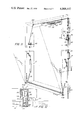
- FIG. 4 is a cross-sectional view taken through the fire vent of FIGS. 1 and 2 showing the structure in somewhat more detail;
- FIG. 5 is a cross-sectional fragmentary view taken along line 5--5 of FIG. 4;
- FIG. 6 is a cross-sectional fragmentary view taken along line 6--6 of FIG. 4;
- FIG. 7 shows the torsion bars of FIG. 4 in their released position
- FIG. 8 is a cross-sectional view through adjacent wall vents disposed on separate floors of a building showing the manner in which a wall vent is released from therebelow;
- FIG. 9 is a fragmentary cross-sectional view in the vicinity of the latch means of this invention showing an electrically oprated means for releasing the latch means;
- FIG. 10 is a perspective view of another embodiment of the invention partially in phantom with the vent hinged along a side edge;
- FIG. 11 is a perspective view of a wall vent partially in phantom and similar in construction to the one shown in the cross-sectional view of FIG. 4 clearly indicating the operation of the release means for the wall vent;
- FIG. 12 is a cross-sectional view taken along line 12--12 of FIG. 11 showing a thinner frame cross-section than the one shown in FIG. 5, for example;
- FIG. 13 is a cross-sectional view taken along line 13--13 of FIG. 11;
- FIG. 14 is a perspective view of another arrangement for releasing the vent
- FIG. 15 is a perspective view of a wall vent partially in phantom and showing an alternate release mechanism
- FIG. 16 is a perspective view similar to that shown in FIG. 15 with still a further release mechanism.
- FIG. 17 shows a portion of the release mechanism shown in FIG. 16 adapted for electrical operation.
- FIG. 1 shows a vent constructed in accordance with the principles of the present invention as viewed from outside of the building which is to be vented.
- FIG. 2 depicts the vent of FIG. 1 as viewed from inside the building.
- the vent generally comprises a fixed rectangular frame 10 which has a generally U-shaped cross-section as indicated in FIG. 5, for example, and a vent 12 including movable frame 13 and panel 44.
- Frame 13 also preferably has a U-shaped cross-section as indicated in FIG. 5, for example, and panel 14 which may be constructed of glass or clear plastic is disposed therein.
- FIG. 1 and 2 show shock absorbers 15 and 16 suitably connected between frame 13 and frame 10. These shock absorbers enable a smooth opening of the vent when it is released and also limit the full open position thereof. The exact location and construction of these shock absorbers is discussed hereinafter with reference to FIGS. 4 and 5.
- FIG. 2 also shows release members 17 and 18 which are disposed on frame 10.
- release member 18 When the release member 18 is slid downwardly, the latch mechanism of the present invention is released and the vent is allowed to open under control of the shock absorbers.
- the upper release member 17, in one embodiment, is used to release a vent disposed in a story thereabove. This mode of operation is discussed in more detail hereinafter with reference to FIG. 8.
- FIGS. 1 and 2 the frame 13 is pivoted at its lower edge from frame 10.
- the frame 20 is pivoted at its top edge from frame 19.
- the embodiment of FIG. 3 may be substantially identical to that shown in FIGS. 1 and 2 wherein both frames have a substantially U-shaped cross-section.
- FIG. 3 also shows a pair of shock absorbers 21 and 22 which may be of the same type as shock absorbers 15 and 16 of FIGS. 1 and 2.
- FIG. 4 there is shown a cross-sectional view through the vent when in a closed position for the embodiment shown in FIGS. 1 and 2.
- FIG. 4 also shows the moveable frame in phantom in its open position with the shock absorber extended.
- FIG. 5 is a cross-sectional view taken along line 5--5 of FIG. 4 and clearly indicates the cross-sectional configuration of the frame 10 and frame 13.
- the frame 10 may be constructed of extruded aluminum and is arranged with a generally U-shaped cross-section as indicated in FIG. 5 having a base wall 25 with walls 26 and 28 extending vertically and integrally therefrom.
- the frames 10 and 13 with their perpendicularly extending walls define an elongated compartment 40 for containing the mechanisms of the present invention.
- a gasket 42 provides a seal between frame 10 and frame 13 and may suitably be secured to base wall 25 and perpendicular wall 28.
- FIG. 6 shows one arrangement for connecting the outer periphery 29 of frame 10 to the building structure 31.
- the panel 14 which is shown in FIG. 5 as being constructed of a suitable insulating material such as glass may be secured to frame 13 in the manner shown in FIG. 5.
- the perpendicular wall 34 has a flange 35 extending inwardly toward the center of the vent.
- a gasket or the like 37 may then be inserted between the outer periphery of panel 14 and flange 35.
- An L-shaped bracket 39 fits against the panel 14 and is secured to window frame 13 by means of a fastener 41.
- a cover panel 44 may be secured to window frame 13, panel 14, and L-shaped bracket 39 for providing a more esthetic appearance from the outside of the building.
- the frame 13 is hinged at its bottom end 46 by means of a double torsion bar as depicted in FIG. 7.
- This double Z-bar normally urges the window away from the frame as indicated in phantom in FIG. 4.
- the bias hinge member shown in FIG. 7 comprises a first Z-shaped bar 50 and a second Z-shaped bar 52.
- the two Z-shaped bars are intercoupled by common connector members 54 and 56.
- the leg 50A of bar 50 and leg 52A of bar 52 are contained within the U-shaped channel defined by frame 10 and the holding member 54 and 56 are suitably secured to the frame 10.
- the other arms 50B and 52B of bars 50 and 52, respectively, are contained within the U-shaped channel defined in frame 13.
- FIG. 7 shows the bars in their relaxed position. However, when the window frame is moved to its closed position the ends of the bars are urged toward each other and a tension is created tending to provide an opening force should the window be released. However, when the window is closed it is maintained in a closed position by means of the latch mechanism 60 shown in FIG. 4 and in a slightly larger view in FIG. 9.
- the torsion bar such as the one shown in FIG. 7, be constructed so that for a given size panel the moveable frame will not open even after it is released if the outside wind velocity is above a given predetermined threshold level such as 30 miles per hour, for example.
- a given predetermined threshold level such as 30 miles per hour, for example.
- the vents of the present invention are preferably designed so that even if a fireman did release a vent not realizing the direction of velocity of the wind, then the window would not open if the wind were above this predetermined velocity.
- the vent if the vent is open, it will close itself if the wind exceeds the predetermined velocity.
- the diameter of the bars can be calculated depending upon the wind speed at which the vent closes.
- the angle of bend of the X-bars is another design consideration taken into account in constructing the torsion bars.
- a release member 18 shown in FIG. 4 and associated pulley 76 which is suitably secured in a conventional manner from frame 10.
- the release member 18 includes a top flange 80 having a cable 82 secured thereto.
- the cable 82 extends vertically as depicted in FIG. 4, extends about pulley 76 and is secured in aperture 84 (see FIG. 9) of hook-shaped member 62.
- FIG. 6 there is shown a cross-sectional view taken along line 6--6 of FIG. 4 showing the frame 10 and frame 13 as being substantially the same as discussed previously with reference to FIG. 5.
- FIG. 6 also shows the pulley 76 and the latch mechanism 60 which have been dicussed previously in detail with reference to FIG. 4.
- This cable couples through the structure 104 to a bottom flange 110 associated with release member 18A.
- the cable 108 is pulled downwardly causing release member 18A to be depressed.
- This causes the latching mechanism associated with frame 10A and vent 12A to be released causing the vent 12 to open.
- This action could also have been caused by depression of release member 18A if access to that floor were possible.
- FIGS. 10-13 similar reference characters previously used with respect to FIGS. 1-9 shall be used where appropriate.
- FIGS. 10 and 11 much of the structural part of the vent have been removed in order to clearly depict the operating apparatus used in association with the vent.
- FIG. 10 there are provided two latch mechanisms 60 which may be identical in design to those shown in FIG. 9.
- the hook-shaped members 62 associated therewith are pivotally supported to the fixed frame and the engaging pins 68 are suitably supported from the moveable frame.
- FIG. 10 shows the release members 17 and 18.
- the release member 18 has a bottom flange 18A having a cable 18B secured thereto for actuating the member 18 from a floor therebelow.
- the top flange 18C of member 18 has a cable 18D extending therefrom around pulley 18E to hook-shaped member 62.
- the release means 17 also has a cable 17A associated therewith for causing release of a vent disposed thereabove.
- this embodiment is quite similar to that previously discussed with reference to FIG. 4, for example.
- One of the differences is in the use of added pivot members 45A and 45B.
- the Z-bars can be held by clips similar to the ones shown in FIG. 10.
- the hinging of the moveable frame is provided by the pivot members and the Z-bars function primarily as a biasing means for urging the moveable frame to its open position.
- FIG. 11 also shows the shock absorbers 15 and 16 which may be similar in design to the shock absorbers shown in FIG. 1, for example.
- FIG. 11 also shows the release members 17 and 18 and latch mechanism 60, one disposed on each side of the vent.
- the latch mechanism 60 shown on the right in FIG. 11 is arranged substantially identically as the one discussed in FIG. 4. However, with the two latch arrangement shown in FIG. 11 the release member 18 with its top flange 80 accommodates a cable 81 in addition to the previously discussed cable 82.
- the cable 81 extends from flange 80 through pulleys 81A and 81B appropriately mounted to the fixed frame, to the left hand latch mechanism 60.
- FIG. 11 also includes means responsive either to smoke or heat causing a release of the moveable frame.
- This heat or smoke element 130 may be similar to the one shown in FIG. 10 and includes an electro-thermal link 132 and spring 140.
- a cable 141 connnects to the fusible link and has its ends split into sections 143 and 144, Section 143 is coupled to cable 81.
- Section 144 extends back thru pulley 81A and is attached to cable 82 just above latch 60. If link 132 is melted the spring 140 causes the cable 141 to be pulled toward the fixed end of the spring and the segments 143 and 144 of the cable cause release of both latch mechanism 60 by pulling on cables 81 and 82.
- FIG. 12 shows a cross-sectional view taken along line 12--12 of FIG. 11. It discloses in this embodiment that the fixed frame 10 and moveable frame 13 are thinner than in the embodiment shown in FIG. 5, for example. In this way, the vent is not too bulky and does not distract from the appearance of a regular window.
- the fixed frame is substantially U-shaped including legs 150 and 152.
- Leg 152 is appropriately connected to the surrounding building construction 154.
- the moveable frame includes an elongated leg 156 which fits adjacent leg 150 and has a body portion 158 for accommodating a panel 14.
- this cross-sectional view shows the Z-bars 50 and 52 appropriately situated in the compartment defined by the two frames.
- FIG. 13 is a cross-sectional view similar to that shown in FIG. 12 but taken along line 13--13 of FIG. 11.
- This embodiment shows the fixed frame 10 and the moveable frame 13 of substantially the same configuration as shown in FIG. 12.
- a shock-absorber 160 fastened at one end between legs 150 and 152 and connected at the other end in U-shaped channel 162 in body 158.
- FIG. 14 shows another electrical arrangement for releasing the latch mechanism such as the one shown in FIG. 11.
- the cable 170 shown in FIG. 14 is analagous to the cable 141 of FIG. 11.
- This cable extends about a pulley 172 suitably supported in the frame and is tied at its end to spring 174.
- the spring has its other end fixed to post 176.
- the moveable end of the spring also engages with arm 180 of pivot member 182.
- the other arm 184 of member 182 is engageable with solenoid 186.
- arm 184 In the solid outline position of FIG. 14 arm 184 is held by the output shaft 187 of the solenoid which is in its extended position.
- the arm 180 holds the spring in its tensioned position.
- arm 184 When the solenoid is actuated via lines 189 by means of an electrical signal from a switch or sensor, arm 184 disengages from shaft 187 and member 182 rotates about pin 183.
- the spring disengages from arm 180 and cable 170 is pulled to the right as viewed in FIG. 14 causing a release of a latch mechanism associated therewith.
- FIG. 15 shows a view similar to that shown in FIG. 11, and discloses a different release mechanism.
- the frame is shown in phantom and primarily only the structure associated with the release mechanism is shown in its position relative to the frame.
- the release mechanism includes latch mechanisms 190 and 191 which are substantially identical to the latch mechanism shown in FIG. 11. However, each of the latch mechanism shown in FIG. 15 does include an adjusting screw 192 which can be used to adjust the closed position of each of the latch mechanisms.
- a cable 193 couples to latch mechanism 190 and extends about pulleys 194 and 195 which are suitably supported from the fixed frame.
- the cable 193 is tied by a crimp device 196 to a downwardly extending cable section 197.
- Cable section 197 also couples to crimp device 199 which has extending therefrom cable section 200.
- the end of cable section 200 ties in a loop 201 which fits within handle 202 by means of a securing pin 204 which is shown exploded from the handle.
- the cable section 200 is bent at point 206 as shown in FIG. 15 and at that point extends through a hole in the frame which is not shown in FIG. 15.
- Another cable section 210 extends from crimp device 196 over pulley 212 and is secured to the other latch mechanism 191.
- the cable sections 193 and 210 cause upward pivoting of the respective latch mechanisms 190 and 191 to permit release of the movable frame and opening of the vent.
- FIG. 16 shows an arrangement similar to that shown in FIG. 15 and like reference characters will be used in FIG. 16 as they apply to the like parts shown in FIG. 15.
- the cable 193 has disposed therein a turn-buckle device 224 which permits fine adjustment of the tension that is to be maintained in the main cable 193 which is shown extending about pulleys 194 and 195.
- the operation of the latch mechanisms 190 and 191, from the handle 202, is substantially identical in FIG. 16 as that discussed with reference to FIG. 15.
- a crimp device 230 has a cable 232 extending therefrom which connects to swivel bar 234.
- the swivel bar 234 may be operated in different manners to also cause release of the latch mechanisms.
- another cable 236 also extends from pivot bar 234 about pulleys 238 and 239, via a turn-buckle arrangement 240 to a crimp device 242 which joins with cable 210 shown previously in FIG. 15 as extending to the latch mechanism 191.
- the turn-buckle arrangement 240 provides fine adjustment for the cable mechanism so that the slack in the different cables can be maintained about the same so that under the different conditions of release, the latch mechanisms 190 and 191 will be substantially concurrently released.
- the pivot bar 234 is releasable by means of a fusible link 244.
- this fusible link opens, the pivot bar 234 is pivoted to pull the cable sections 232 and 236 and cause release of the latch mechanisms 190 and 191, respectively.
- FIG. 17 shows, in somewhat more detail, the pivot bar 234 and pulley 238.
- the pivot bar 234 is released by means of a solenoid 250.
- the pivot bar can also be connected to a fusible link for actuation thereby.
Landscapes
- Business, Economics & Management (AREA)
- Emergency Management (AREA)
- Health & Medical Sciences (AREA)
- Public Health (AREA)
- Special Wing (AREA)
Priority Applications (1)
| Application Number | Priority Date | Filing Date | Title |
|---|---|---|---|
| US05/726,578 US4104834A (en) | 1974-12-11 | 1976-09-27 | Fire vent |
Applications Claiming Priority (1)
| Application Number | Priority Date | Filing Date | Title |
|---|---|---|---|
| US34178073A | 1973-03-15 | 1973-03-15 |
Related Parent Applications (2)
| Application Number | Title | Priority Date | Filing Date |
|---|---|---|---|
| US34178073A Continuation-In-Part | 1973-03-15 | 1973-03-15 | |
| US34178073A Division | 1973-03-15 | 1973-03-15 |
Related Child Applications (1)
| Application Number | Title | Priority Date | Filing Date |
|---|---|---|---|
| US05/726,578 Division US4104834A (en) | 1974-12-11 | 1976-09-27 | Fire vent |
Publications (1)
| Publication Number | Publication Date |
|---|---|
| US4068417A true US4068417A (en) | 1978-01-17 |
Family
ID=23339009
Family Applications (1)
| Application Number | Title | Priority Date | Filing Date |
|---|---|---|---|
| US05/531,808 Expired - Lifetime US4068417A (en) | 1973-03-15 | 1974-12-11 | Fire vent |
Country Status (2)
| Country | Link |
|---|---|
| US (1) | US4068417A (fr) |
| CA (1) | CA1027806A (fr) |
Cited By (9)
| Publication number | Priority date | Publication date | Assignee | Title |
|---|---|---|---|---|
| US4304070A (en) * | 1978-05-01 | 1981-12-08 | Charles Citelli | Emergency air vent structure |
| US5044133A (en) * | 1988-12-13 | 1991-09-03 | Wasco Products, Inc. | Skylight construction |
| WO2004063511A1 (fr) * | 2003-01-09 | 2004-07-29 | SCHÜCO International KG | Fenetre ou porte comportant un dispositif d'entrainement |
| US20060151976A1 (en) * | 2003-10-08 | 2006-07-13 | Takata Corporation | Airbag and airbag apparatus |
| US20070210737A1 (en) * | 2006-02-24 | 2007-09-13 | David Brander | Window convenience and security system |
| US7591102B1 (en) * | 2004-10-12 | 2009-09-22 | Rob Evans | Emergency door opening actuator |
| ITTO20110115A1 (it) * | 2011-02-11 | 2012-08-12 | Savio Spa | Evacuatore di fumo e calore |
| US20130199736A1 (en) * | 2010-10-20 | 2013-08-08 | Yoo Sun Ro | Automatically closed fire protection louver device |
| US20130227891A1 (en) * | 2010-06-22 | 2013-09-05 | Cox Architects Pty Ltd | Fire shutter |
Citations (20)
| Publication number | Priority date | Publication date | Assignee | Title |
|---|---|---|---|---|
| US712256A (en) * | 1902-06-13 | 1902-10-28 | Beardsley Gregory And Kirshner | Apparatus for automatically operating fire-doors. |
| US1864357A (en) * | 1930-07-14 | 1932-06-21 | Detroit Steel Products Co | Thermostatic releasing means for self-closing ventilators |
| GB403294A (en) * | 1932-05-28 | 1933-12-21 | Alfr Andersen Mek Verksted & S | Steel casement window frame |
| GB776843A (en) * | 1955-02-04 | 1957-06-12 | Henry Hope & Sons Ltd | Window actuating mechanism |
| US2803319A (en) * | 1955-05-26 | 1957-08-20 | Loyd C Johnson | Transom adjuster |
| US2812835A (en) * | 1956-05-11 | 1957-11-12 | Mohawk Heat Relief Co | Automatic ventilator |
| US2827003A (en) * | 1954-01-20 | 1958-03-18 | Wasco Products | Combination skylight and fire vent construction |
| US2842809A (en) * | 1952-12-23 | 1958-07-15 | Pullman Standard Car Mfg Co | Laterally movable door arrangement |
| US3115224A (en) * | 1961-12-26 | 1963-12-24 | Ceco Steel Products Corp | Automatic ventilator closing device |
| US3207273A (en) * | 1962-07-20 | 1965-09-21 | Garcy Corp | Closure release device |
| US3337990A (en) * | 1964-05-26 | 1967-08-29 | Iwata Yoshiaki | Temperature controlled windows |
| US3438147A (en) * | 1966-10-20 | 1969-04-15 | White Consolidated Ind Inc | Disconnect for doors |
| US3453777A (en) * | 1967-11-07 | 1969-07-08 | American Cyanamid Co | Pressure venting panel assembly |
| US3516210A (en) * | 1968-11-19 | 1970-06-23 | Wasco Products | Fire and smoke relief ventilator sky-light dome |
| GB1198535A (en) * | 1968-03-05 | 1970-07-15 | Westland Engineers Ltd | Improvements in or relating to Doors. |
| US3557497A (en) * | 1968-09-11 | 1971-01-26 | Robertson Co H H | Explosive pressure and/or heat and smoke venting unit |
| US3589065A (en) * | 1969-12-09 | 1971-06-29 | Bohem Mfg Co Inc | Fire vent hatch |
| US3601437A (en) * | 1970-07-06 | 1971-08-24 | Robert J Lyons | Emergency-releasable latch for hatchway door |
| US3757471A (en) * | 1971-11-09 | 1973-09-11 | Allied Prod Corp | Curtain wall safety panel |
| US3777241A (en) * | 1971-05-24 | 1973-12-04 | C Wenger | Control specifically for animal buildings |
-
1974
- 1974-03-11 CA CA194,573A patent/CA1027806A/fr not_active Expired
- 1974-12-11 US US05/531,808 patent/US4068417A/en not_active Expired - Lifetime
Patent Citations (20)
| Publication number | Priority date | Publication date | Assignee | Title |
|---|---|---|---|---|
| US712256A (en) * | 1902-06-13 | 1902-10-28 | Beardsley Gregory And Kirshner | Apparatus for automatically operating fire-doors. |
| US1864357A (en) * | 1930-07-14 | 1932-06-21 | Detroit Steel Products Co | Thermostatic releasing means for self-closing ventilators |
| GB403294A (en) * | 1932-05-28 | 1933-12-21 | Alfr Andersen Mek Verksted & S | Steel casement window frame |
| US2842809A (en) * | 1952-12-23 | 1958-07-15 | Pullman Standard Car Mfg Co | Laterally movable door arrangement |
| US2827003A (en) * | 1954-01-20 | 1958-03-18 | Wasco Products | Combination skylight and fire vent construction |
| GB776843A (en) * | 1955-02-04 | 1957-06-12 | Henry Hope & Sons Ltd | Window actuating mechanism |
| US2803319A (en) * | 1955-05-26 | 1957-08-20 | Loyd C Johnson | Transom adjuster |
| US2812835A (en) * | 1956-05-11 | 1957-11-12 | Mohawk Heat Relief Co | Automatic ventilator |
| US3115224A (en) * | 1961-12-26 | 1963-12-24 | Ceco Steel Products Corp | Automatic ventilator closing device |
| US3207273A (en) * | 1962-07-20 | 1965-09-21 | Garcy Corp | Closure release device |
| US3337990A (en) * | 1964-05-26 | 1967-08-29 | Iwata Yoshiaki | Temperature controlled windows |
| US3438147A (en) * | 1966-10-20 | 1969-04-15 | White Consolidated Ind Inc | Disconnect for doors |
| US3453777A (en) * | 1967-11-07 | 1969-07-08 | American Cyanamid Co | Pressure venting panel assembly |
| GB1198535A (en) * | 1968-03-05 | 1970-07-15 | Westland Engineers Ltd | Improvements in or relating to Doors. |
| US3557497A (en) * | 1968-09-11 | 1971-01-26 | Robertson Co H H | Explosive pressure and/or heat and smoke venting unit |
| US3516210A (en) * | 1968-11-19 | 1970-06-23 | Wasco Products | Fire and smoke relief ventilator sky-light dome |
| US3589065A (en) * | 1969-12-09 | 1971-06-29 | Bohem Mfg Co Inc | Fire vent hatch |
| US3601437A (en) * | 1970-07-06 | 1971-08-24 | Robert J Lyons | Emergency-releasable latch for hatchway door |
| US3777241A (en) * | 1971-05-24 | 1973-12-04 | C Wenger | Control specifically for animal buildings |
| US3757471A (en) * | 1971-11-09 | 1973-09-11 | Allied Prod Corp | Curtain wall safety panel |
Cited By (14)
| Publication number | Priority date | Publication date | Assignee | Title |
|---|---|---|---|---|
| US4304070A (en) * | 1978-05-01 | 1981-12-08 | Charles Citelli | Emergency air vent structure |
| US5044133A (en) * | 1988-12-13 | 1991-09-03 | Wasco Products, Inc. | Skylight construction |
| WO2004063511A1 (fr) * | 2003-01-09 | 2004-07-29 | SCHÜCO International KG | Fenetre ou porte comportant un dispositif d'entrainement |
| US20090160164A9 (en) * | 2003-10-08 | 2009-06-25 | Takata Corporation | Airbag and airbag apparatus |
| US20060151976A1 (en) * | 2003-10-08 | 2006-07-13 | Takata Corporation | Airbag and airbag apparatus |
| US7591102B1 (en) * | 2004-10-12 | 2009-09-22 | Rob Evans | Emergency door opening actuator |
| US20070210737A1 (en) * | 2006-02-24 | 2007-09-13 | David Brander | Window convenience and security system |
| US20130227891A1 (en) * | 2010-06-22 | 2013-09-05 | Cox Architects Pty Ltd | Fire shutter |
| US8844195B2 (en) * | 2010-06-22 | 2014-09-30 | Cox Architects Pty Ltd | Fire shutter |
| US20130199736A1 (en) * | 2010-10-20 | 2013-08-08 | Yoo Sun Ro | Automatically closed fire protection louver device |
| US8881455B2 (en) * | 2010-10-20 | 2014-11-11 | GL World Tech C&S Ltd. Co. | Automatically closed fire protection louver device |
| ITTO20110115A1 (it) * | 2011-02-11 | 2012-08-12 | Savio Spa | Evacuatore di fumo e calore |
| WO2012107903A1 (fr) | 2011-02-11 | 2012-08-16 | Savio S.P.A. | Evacuateur de fumée et de chaleur |
| CN103443557A (zh) * | 2011-02-11 | 2013-12-11 | 萨维奥股份有限公司 | 烟气和热量排出装置 |
Also Published As
| Publication number | Publication date |
|---|---|
| CA1027806A (fr) | 1978-03-14 |
Similar Documents
| Publication | Publication Date | Title |
|---|---|---|
| US4304070A (en) | Emergency air vent structure | |
| US4104834A (en) | Fire vent | |
| US4068417A (en) | Fire vent | |
| US3399500A (en) | Automatic roof vent | |
| US2827003A (en) | Combination skylight and fire vent construction | |
| US3830016A (en) | Latch mechanism for hatchway leaf | |
| US4452010A (en) | Window security system | |
| JPS61238256A (ja) | 安全キヤビネツト掛金装置 | |
| US3601437A (en) | Emergency-releasable latch for hatchway door | |
| US20200289861A1 (en) | Fire rated pet door assembly and activation system | |
| US7004287B1 (en) | Hidden fire escape | |
| US2554822A (en) | Door construction | |
| CN211357513U (zh) | 挡烟闭火防蔓延智能窒息控火系统 | |
| GB1384862A (en) | Fire door structure and fire safety installation including said door structure | |
| US4180142A (en) | Emergency escape openable skylight | |
| US4578900A (en) | Ventilation apparatus | |
| GB2310888A (en) | Canopy window:remote operation | |
| CN215485464U (zh) | 一种防火窗闭窗装置 | |
| CA1036425A (fr) | Event d'incendie | |
| US2923226A (en) | Fire venting roof structure | |
| US3715967A (en) | Power roof exhauster or heat relief vent | |
| US3977134A (en) | Vent closure arrangement | |
| US3963097A (en) | Fire ladder | |
| GB2125884A (en) | Hatch or rooflight opening mechanism | |
| JPS5834367Y2 (ja) | 換気扇等の防火シャッタ |
Legal Events
| Date | Code | Title | Description |
|---|---|---|---|
| AS | Assignment |
Owner name: SAWCO, INC., P.O. BOX 351, SANFORD, MAINE 04073 A Free format text: ASSIGNMENT OF ASSIGNORS INTEREST.;ASSIGNOR:WASCO PRODUCTS, INC.;REEL/FRAME:004195/0763 Effective date: 19830630 Owner name: CASCO BANK & TRUST COMPANY, ONE MONUMENT SQUARE, P Free format text: AS COLLATERAL SECURITY FOR LOANS RECITED, ASSIGNOR ASSIGNS THE ENTIRE INTREST, SUBJECT TO CONDITIONS RECITED;ASSIGNOR:SAWCO, INC.;REEL/FRAME:004195/0769 Effective date: 19830630 Owner name: WASCO PRODUCTS, INC., P.O. BOX 351, SANFORD, MAINE Free format text: AS COLLATERAL SECURITY FOR LOANS RECITED, ASSIGNOR DOES HEREBY ASSIGN THE ENTIRE INTEREST;ASSIGNOR:SAWCO, INC.;REEL/FRAME:004195/0776 Effective date: 19830630 Owner name: WASCO PRODUCTS, INC., A MAINE CORP., MAINE Free format text: AS COLLATERAL SECURITY FOR LOANS RECITED, ASSIGNOR DOES HEREBY ASSIGN THE ENTIRE INTEREST;ASSIGNOR:SAWCO, INC.;REEL/FRAME:004195/0776 Effective date: 19830630 Owner name: CASCO BANK & TRUST COMPANY, A MAINE BANKING INSTIT Free format text: AS COLLATERAL SECURITY FOR LOANS RECITED, ASSIGNOR ASSIGNS THE ENTIRE INTREST, SUBJECT TO CONDITIONS RECITED;ASSIGNOR:SAWCO, INC.;REEL/FRAME:004195/0769 Effective date: 19830630 Owner name: SAWCO, INC., A CORP., MAINE Free format text: ASSIGNMENT OF ASSIGNORS INTEREST;ASSIGNOR:WASCO PRODUCTS, INC.;REEL/FRAME:004195/0763 Effective date: 19830630 |
|
| STCF | Information on status: patent grant |
Free format text: PATENTED FILE - (OLD CASE ADDED FOR FILE TRACKING PURPOSES) |
|
| AS | Assignment |
Owner name: CASCO BANK & TRUST COMPANY, ONE MONUMENT SQUARE, P Free format text: RELEASED BY SECURED PARTY;ASSIGNOR:SAWCO, INC., A CORP OF MAINE;REEL/FRAME:004531/0241 Effective date: 19851029 Owner name: WASCO PRODUCTS, INC. Free format text: CHANGE OF NAME;ASSIGNOR:SAWCO, INC.;REEL/FRAME:004531/0225 Effective date: 19830810 Owner name: C.G.M., INC. Free format text: CHANGE OF NAME;ASSIGNOR:WASCO PRODUCTS, INC.;REEL/FRAME:004531/0227 Effective date: 19860630 Owner name: WASCO PRODUCTS, INC., P. O. BOX 351 SANFORD, MAINE Free format text: RELEASED BY SECURED PARTY;ASSIGNOR:C.G.M., INC., A CORP OF MAINE;REEL/FRAME:004531/0231 Effective date: 19851105 |