US4078638A - Oil pressure shock absorber - Google Patents
Oil pressure shock absorber Download PDFInfo
- Publication number
- US4078638A US4078638A US05/757,031 US75703177A US4078638A US 4078638 A US4078638 A US 4078638A US 75703177 A US75703177 A US 75703177A US 4078638 A US4078638 A US 4078638A
- Authority
- US
- United States
- Prior art keywords
- inner cylinder
- outer cylinder
- cylinder
- tip
- shock absorber
- Prior art date
- Legal status (The legal status is an assumption and is not a legal conclusion. Google has not performed a legal analysis and makes no representation as to the accuracy of the status listed.)
- Expired - Lifetime
Links
Images

Classifications
-
- F—MECHANICAL ENGINEERING; LIGHTING; HEATING; WEAPONS; BLASTING
- F16—ENGINEERING ELEMENTS AND UNITS; GENERAL MEASURES FOR PRODUCING AND MAINTAINING EFFECTIVE FUNCTIONING OF MACHINES OR INSTALLATIONS; THERMAL INSULATION IN GENERAL
- F16F—SPRINGS; SHOCK-ABSORBERS; MEANS FOR DAMPING VIBRATION
- F16F9/00—Springs, vibration-dampers, shock-absorbers, or similarly-constructed movement-dampers using a fluid or the equivalent as damping medium
- F16F9/32—Details
- F16F9/34—Special valve constructions; Shape or construction of throttling passages
- F16F9/346—Throttling passages in the form of slots arranged in cylinder walls
-
- F—MECHANICAL ENGINEERING; LIGHTING; HEATING; WEAPONS; BLASTING
- F16—ENGINEERING ELEMENTS AND UNITS; GENERAL MEASURES FOR PRODUCING AND MAINTAINING EFFECTIVE FUNCTIONING OF MACHINES OR INSTALLATIONS; THERMAL INSULATION IN GENERAL
- F16F—SPRINGS; SHOCK-ABSORBERS; MEANS FOR DAMPING VIBRATION
- F16F9/00—Springs, vibration-dampers, shock-absorbers, or similarly-constructed movement-dampers using a fluid or the equivalent as damping medium
- F16F9/06—Springs, vibration-dampers, shock-absorbers, or similarly-constructed movement-dampers using a fluid or the equivalent as damping medium using both gas and liquid
- F16F9/063—Springs, vibration-dampers, shock-absorbers, or similarly-constructed movement-dampers using a fluid or the equivalent as damping medium using both gas and liquid comprising a hollow piston rod
-
- F—MECHANICAL ENGINEERING; LIGHTING; HEATING; WEAPONS; BLASTING
- F16—ENGINEERING ELEMENTS AND UNITS; GENERAL MEASURES FOR PRODUCING AND MAINTAINING EFFECTIVE FUNCTIONING OF MACHINES OR INSTALLATIONS; THERMAL INSULATION IN GENERAL
- F16F—SPRINGS; SHOCK-ABSORBERS; MEANS FOR DAMPING VIBRATION
- F16F9/00—Springs, vibration-dampers, shock-absorbers, or similarly-constructed movement-dampers using a fluid or the equivalent as damping medium
- F16F9/32—Details
- F16F9/48—Arrangements for providing different damping effects at different parts of the stroke
Definitions
- This invention relates to oil pressure shock absorbers and more particularly to an oil pressure shock absorber for absorbing a collision energy which is easy to make and assemble and is to be used to fit a bumper to an automobile.
- Such oil pressure shock absorber can most effectively reduce shocks by uniformly absorbing a collision energy over the entire range of the stroke.
- the operating velocity of the shock absorber is highest in the initial period of a collision and becomes zero in the end period, in order to obtain a uniform attenuating force over the entire range of the stroke from the initial period to the end period of the collision, it is necessary to gradually increase the oil flow resistance. Therefore, in the prior art, there has been taken such means as of gradually varying the depth of the oil flowing groove in the axial direction.
- shock absorber has been complicated in the structure and very troublesome to make.
- the prior shock absorber is difficult to be assembled and when it is once assembled, it is impossible to be disassembled and repaired, thus providing an uneconomical result.
- an object of the present invention is to provide an oil pressure shock absorber which can uniformly absorb a collision energy over the entire range of the stroke with a simple structure easy to manufacture.
- Another object of the present invention is to provide an oil pressure shock absorber which can be disassembled.
- an oil pressure shock absorber comprises an outer cylinder fixed at, the base end to a car body, an inner cylinder slidably fitted in the tip part in the outer cylinder and having a bracket at the base end and a free piston fitted in the inner cylinder, the inner cylinder has a plurality of orifices arranged in the axial direction on the side wall thereof and is provided with concave grooves in the axial direction from the tip on the outside surface thereof, the outer cylinder has an annular concave groove formed on the inside surface thereof so as to be opposed to the orifices, a high pressure gas is enclosed between the free piston and the base of the inner cylinder and the space between the free piston and the tip of the inner cylinder and the interior of the outer cylinder are filled with oil.
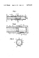
- FIG. 1 is a vertically sectional view showing an oil pressure shock absorber embodying the present invention.
- FIG. 2 is a vertically sectional enlarged view of FIG. 1.
- FIG. 3 is a sectional view taken along line III--III in FIG. 2.
- FIG. 4 is a vertically sectional enlarged view of another embodiment of stopper mechanism.
- FIG. 5 is a sectional view on line V--V in FIG. 4.
- FIG. 6 is an enlarged view of a part of the embodiment shown in FIG. 4.
- An inner cylinder 1 is slidably fitted in the tip part inside an outer cylinder 2, is provided with an oil-sealing O-ring 3 in its sliding contact part, has a free piston 5 having on O-ring 4 fitted on the inside and a bracket 6 for fitting, for example, a bumper of an automobile formed at the base end and is closed at the tip with a bottom plate 7 provided with an orifice 8.
- a snap ring 9 is fitted on the inside surface of the inner cylinder so as to be a stopper for the free piston 5.
- a screw 10 for fixing to an automobile body or the like is provided to project in the axial direction at the base end of the outer cylinder 2. Further, a supporting plate 12 is provided through a rubber ring 11 in a proper position outside the outer cylinder 2.
- An oil inlet hole 13 is provided at the base end of the outer cylinder 2 and is closed with a ball 14. Further, the outer cylinder 2 is calked inward at the tip so as to engage with a step part provided on the outer periphery of the inner cylinder 1 and to prevent said inner cylinder from escaping out of the outer cylinder.
- a plurality of orifices 15 aligned in the axial direction are provided in the tip part of such inner cylinder 1 as is described above.
- Such annular concave groove 16 as is opposed to the above mentioned orifices is formed on the inside surface of the outer cylinder 2.
- a plurality of axial concave grooves 17 reaching a proper position from the tip are provided on the outside surface of the inner cylinder.
- a high pressure gas 18 is enclosed between the free piston 5 in the inner cylinder 1 and the base end of the inner cylinder 1.
- the space between the free piston 5 and the tip part of the inner cylinder 1 and the interior of the outer cylinder 2 are filled with oil so that no gap may be made.
- the outer cylinder 2 is provided on the inner surface of its opening part with an annular concave groove 22 and a snap ring 24 having a cut-out portion 23 is fitted in the concave groove 22.
- the snap ring 24 is urged to be in contact with a step portion 21 formed on the outer surface of the inner cylinder 1, thereby preventing the inner cylinder from escaping from the outer cylinder 2 by the pressure of a gas 18.
- a plurality of axial cut-out grooves 25 (three grooves are shown in FIG.
- the above described embodiment of the stopper mechanism of the present invention is provided with the snap ring fitted in the end of the outer cylinder in the oil pressure shock absorber for absorbing a collision energy and a plurality of the cut-out grooves 25 formed at the extreme end of the outer cylinder.
- the attenuating force generated by the passage of the oil through the above mentioned orifices will be kept substantially constant irrespective of the moving position of the inner cylinder and the collision energy will be able to be substantially uniformly absorbed over the entire range of the stoke of the inner cylinder.
- the shock absorber As described above, in the shock absorber according to the present invention, as the collision energy can be substantially uniformly absorbed over the entire range of the compression stroke, if the stoke is made constant, the shock will be able to be very effectively reduced. Further, only the annular concave groove is provided on the inside surface of the outer cylinder and the axial concave grooves and the plurality of orifices are provided in the inner cylinder but such complicated structure as a supporting pillar provided with a piston or many orifices or oil flowing concave grooves and set at the center is not required and therefore this shock absorber is easy to manufacture, assemble and disassemble. Therefore, when an oil seal is damaged or some parts are damaged by the collision of the automobile, the repair can be easily made.
Landscapes
- Engineering & Computer Science (AREA)
- General Engineering & Computer Science (AREA)
- Mechanical Engineering (AREA)
- Fluid-Damping Devices (AREA)
Applications Claiming Priority (4)
| Application Number | Priority Date | Filing Date | Title |
|---|---|---|---|
| JP11658976A JPS5343175A (en) | 1976-09-30 | 1976-09-30 | Hydraulic buffer |
| JA51-116589 | 1976-09-30 | ||
| JA51-136849 | 1976-11-16 | ||
| JP13684976A JPS5362072A (en) | 1976-11-16 | 1976-11-16 | Hydraulic buffer |
Publications (1)
| Publication Number | Publication Date |
|---|---|
| US4078638A true US4078638A (en) | 1978-03-14 |
Family
ID=26454890
Family Applications (1)
| Application Number | Title | Priority Date | Filing Date |
|---|---|---|---|
| US05/757,031 Expired - Lifetime US4078638A (en) | 1976-09-30 | 1977-01-05 | Oil pressure shock absorber |
Country Status (2)
| Country | Link |
|---|---|
| US (1) | US4078638A (fr) |
| CA (1) | CA1054639A (fr) |
Cited By (23)
| Publication number | Priority date | Publication date | Assignee | Title |
|---|---|---|---|---|
| US4312499A (en) * | 1978-02-16 | 1982-01-26 | Fichtel & Sachs Ag | Shock absorber assembly with operationally controlled hydraulic-mechanical damping system |
| US4756512A (en) * | 1986-12-15 | 1988-07-12 | Miner Enterprises, Inc. | Heavy off-road large vehicle suspension strut |
| US5242157A (en) * | 1990-09-22 | 1993-09-07 | Boge Aktiengesellschaft | Impact damper |
| WO1994017317A1 (fr) * | 1993-01-20 | 1994-08-04 | ZIMMER, Günther, Stephan | Amortisseur hydraulique |
| US5720368A (en) * | 1997-03-03 | 1998-02-24 | Caterpillar Inc. | Snubber for a hydraulic cylinder |
| US5797593A (en) * | 1995-12-06 | 1998-08-25 | Showa Coporation | Gas spring |
| US5908123A (en) * | 1997-01-21 | 1999-06-01 | Keystone Industries, Inc. | Rail car buffer and method |
| WO2000010742A1 (fr) * | 1998-08-21 | 2000-03-02 | Avm, Inc. | Procede de production de ressorts a gaz |
| US6047839A (en) * | 1998-02-03 | 2000-04-11 | Huggins; Russell J. | Rail car buffer |
| US6109400A (en) * | 1997-07-09 | 2000-08-29 | Mannesmann Boge Gmbh | Impact absorber |
| AU2003203440B2 (en) * | 2000-09-28 | 2003-06-12 | Robertson, Graeme K | Suspension system |
| US20030111307A1 (en) * | 2001-12-17 | 2003-06-19 | Zf Boge Gmbh | Impact damper |
| US7000907B2 (en) * | 2001-05-10 | 2006-02-21 | Dt Swiss Inc. | Spring system for bicycles |
| US20060091591A1 (en) * | 2001-09-27 | 2006-05-04 | Robertson Graeme K | Suspension system |
| US20060175796A1 (en) * | 2004-12-17 | 2006-08-10 | Ohlins Racing Ab | Device pertaining to a telescopic leg for a motor cycle |
| US20060266602A1 (en) * | 2003-08-12 | 2006-11-30 | Robertson Graeme K | Shock absorber assembly |
| WO2009108122A1 (fr) * | 2008-02-28 | 2009-09-03 | Singapore Technologies Kinetics Ltd | Absorbeur de chocs à déplacement constant |
| US20100320656A1 (en) * | 2005-11-29 | 2010-12-23 | Martin Achenbach | Spring system, in particular for bicycles |
| US20130187316A1 (en) * | 2012-01-23 | 2013-07-25 | Dadco, Inc. | Gas Spring |
| US20170219044A1 (en) * | 2016-01-29 | 2017-08-03 | Suspa Gmbh | Gas pressure spring |
| US10598246B2 (en) | 2017-06-06 | 2020-03-24 | Reyco Granning, Llc | Strut assembly with combined gas spring and damper |
| US20220145771A1 (en) * | 2020-11-10 | 2022-05-12 | Pratt & Whitney Canada Corp. | Variable guide vane assembly and bushing ring therefor |
| US11408705B2 (en) | 2013-12-16 | 2022-08-09 | Ravin Crossbows, Llc | Reduced length crossbow |
Citations (9)
| Publication number | Priority date | Publication date | Assignee | Title |
|---|---|---|---|---|
| FR1069537A (fr) * | 1953-01-10 | 1954-07-08 | Amortisseur hydraulique télescopique | |
| DE1109968B (de) * | 1959-10-08 | 1961-06-29 | Marie Lucien Louis B Christian | Abschlussdeckel fuer Zylinder, insbesondere von hydraulischen Stossdaempfern, mit dichter Kolbenstangendurchfuehrung |
| US3491993A (en) * | 1967-08-03 | 1970-01-27 | Harold W Scholin | Adjustable hydraulic shock absorber |
| US3788433A (en) * | 1972-06-28 | 1974-01-29 | Tokico Ltd | Telescopic suspension unit |
| US3804217A (en) * | 1972-03-13 | 1974-04-16 | Monroe Belgium Nv | Pressurized shock absorber |
| US3870130A (en) * | 1972-05-15 | 1975-03-11 | Gabriel Of Canada Limited | Shock absorber |
| DE2166749A1 (de) * | 1971-07-14 | 1975-06-26 | Bilstein August Fa | Aufpralldaempfer fuer die abstuetzung von stosstangen an kraftfahrzeugen |
| US3904182A (en) * | 1972-10-30 | 1975-09-09 | Allinquant F M | Hydraulic shock absorber and pneumatic spring device |
| US3944198A (en) * | 1973-11-30 | 1976-03-16 | Aisin Seiki Kabushiki Kaisha | Impact absorber |
-
1977
- 1977-01-05 US US05/757,031 patent/US4078638A/en not_active Expired - Lifetime
- 1977-01-12 CA CA269557A patent/CA1054639A/fr not_active Expired
Patent Citations (9)
| Publication number | Priority date | Publication date | Assignee | Title |
|---|---|---|---|---|
| FR1069537A (fr) * | 1953-01-10 | 1954-07-08 | Amortisseur hydraulique télescopique | |
| DE1109968B (de) * | 1959-10-08 | 1961-06-29 | Marie Lucien Louis B Christian | Abschlussdeckel fuer Zylinder, insbesondere von hydraulischen Stossdaempfern, mit dichter Kolbenstangendurchfuehrung |
| US3491993A (en) * | 1967-08-03 | 1970-01-27 | Harold W Scholin | Adjustable hydraulic shock absorber |
| DE2166749A1 (de) * | 1971-07-14 | 1975-06-26 | Bilstein August Fa | Aufpralldaempfer fuer die abstuetzung von stosstangen an kraftfahrzeugen |
| US3804217A (en) * | 1972-03-13 | 1974-04-16 | Monroe Belgium Nv | Pressurized shock absorber |
| US3870130A (en) * | 1972-05-15 | 1975-03-11 | Gabriel Of Canada Limited | Shock absorber |
| US3788433A (en) * | 1972-06-28 | 1974-01-29 | Tokico Ltd | Telescopic suspension unit |
| US3904182A (en) * | 1972-10-30 | 1975-09-09 | Allinquant F M | Hydraulic shock absorber and pneumatic spring device |
| US3944198A (en) * | 1973-11-30 | 1976-03-16 | Aisin Seiki Kabushiki Kaisha | Impact absorber |
Cited By (38)
| Publication number | Priority date | Publication date | Assignee | Title |
|---|---|---|---|---|
| US4312499A (en) * | 1978-02-16 | 1982-01-26 | Fichtel & Sachs Ag | Shock absorber assembly with operationally controlled hydraulic-mechanical damping system |
| US4756512A (en) * | 1986-12-15 | 1988-07-12 | Miner Enterprises, Inc. | Heavy off-road large vehicle suspension strut |
| US5242157A (en) * | 1990-09-22 | 1993-09-07 | Boge Aktiengesellschaft | Impact damper |
| WO1994017317A1 (fr) * | 1993-01-20 | 1994-08-04 | ZIMMER, Günther, Stephan | Amortisseur hydraulique |
| US5797593A (en) * | 1995-12-06 | 1998-08-25 | Showa Coporation | Gas spring |
| US5908123A (en) * | 1997-01-21 | 1999-06-01 | Keystone Industries, Inc. | Rail car buffer and method |
| US5720368A (en) * | 1997-03-03 | 1998-02-24 | Caterpillar Inc. | Snubber for a hydraulic cylinder |
| US6109400A (en) * | 1997-07-09 | 2000-08-29 | Mannesmann Boge Gmbh | Impact absorber |
| US6047839A (en) * | 1998-02-03 | 2000-04-11 | Huggins; Russell J. | Rail car buffer |
| GB2357821A (en) * | 1998-08-21 | 2001-07-04 | Avm Inc | Method of manufacturing gas springs |
| GB2357821B (en) * | 1998-08-21 | 2002-05-15 | Avm Inc | Method of manufacturing gas springs |
| US6425279B1 (en) * | 1998-08-21 | 2002-07-30 | Avm, Inc. | Method of manufacturing gas springs |
| WO2000010742A1 (fr) * | 1998-08-21 | 2000-03-02 | Avm, Inc. | Procede de production de ressorts a gaz |
| AU2003203440B2 (en) * | 2000-09-28 | 2003-06-12 | Robertson, Graeme K | Suspension system |
| AU2003203440B8 (en) * | 2000-09-28 | 2009-05-28 | Robertson, Graeme K | Suspension system |
| US20040004316A1 (en) * | 2000-09-28 | 2004-01-08 | Robertson Graeme Kershaw | Suspension system |
| US7000907B2 (en) * | 2001-05-10 | 2006-02-21 | Dt Swiss Inc. | Spring system for bicycles |
| US20060091591A1 (en) * | 2001-09-27 | 2006-05-04 | Robertson Graeme K | Suspension system |
| US20090260937A1 (en) * | 2001-09-27 | 2009-10-22 | Graeme Kershaw Robertson | Suspension system |
| US7753179B2 (en) | 2001-09-27 | 2010-07-13 | Robertson Suspension Systems Pty Ltd. | Suspension system |
| US20030111307A1 (en) * | 2001-12-17 | 2003-06-19 | Zf Boge Gmbh | Impact damper |
| US6913126B2 (en) * | 2001-12-17 | 2005-07-05 | Zf Boge Gmbh | Impact damper |
| USRE44609E1 (en) | 2003-08-12 | 2013-11-26 | Graeme Kershaw Robertson | Shock absorber assembly |
| US20060266602A1 (en) * | 2003-08-12 | 2006-11-30 | Robertson Graeme K | Shock absorber assembly |
| US7513490B2 (en) | 2003-08-12 | 2009-04-07 | Graeme Kershaw Robertson | Shock absorber assembly |
| US20060175796A1 (en) * | 2004-12-17 | 2006-08-10 | Ohlins Racing Ab | Device pertaining to a telescopic leg for a motor cycle |
| US20100320656A1 (en) * | 2005-11-29 | 2010-12-23 | Martin Achenbach | Spring system, in particular for bicycles |
| US8944422B2 (en) * | 2005-11-29 | 2015-02-03 | Dt Swiss, Inc. | Spring system for bicycles |
| WO2009108122A1 (fr) * | 2008-02-28 | 2009-09-03 | Singapore Technologies Kinetics Ltd | Absorbeur de chocs à déplacement constant |
| US20130187316A1 (en) * | 2012-01-23 | 2013-07-25 | Dadco, Inc. | Gas Spring |
| US9416840B2 (en) * | 2012-01-23 | 2016-08-16 | Dadco, Inc. | Gas spring |
| US11408705B2 (en) | 2013-12-16 | 2022-08-09 | Ravin Crossbows, Llc | Reduced length crossbow |
| US20170219044A1 (en) * | 2016-01-29 | 2017-08-03 | Suspa Gmbh | Gas pressure spring |
| US10557515B2 (en) * | 2016-01-29 | 2020-02-11 | Suspa Gmbh | Gas pressure spring |
| US10598246B2 (en) | 2017-06-06 | 2020-03-24 | Reyco Granning, Llc | Strut assembly with combined gas spring and damper |
| US20220145771A1 (en) * | 2020-11-10 | 2022-05-12 | Pratt & Whitney Canada Corp. | Variable guide vane assembly and bushing ring therefor |
| CN114526266A (zh) * | 2020-11-10 | 2022-05-24 | 普拉特 - 惠特尼加拿大公司 | 可变导向叶片组件及其衬套环 |
| US11725533B2 (en) * | 2020-11-10 | 2023-08-15 | Pratt & Whitney Canada Corp. | Variable guide vane assembly and bushing ring therefor |
Also Published As
| Publication number | Publication date |
|---|---|
| CA1054639A (fr) | 1979-05-15 |
Similar Documents
| Publication | Publication Date | Title |
|---|---|---|
| US4078638A (en) | Oil pressure shock absorber | |
| US5181589A (en) | Reversible impact damper, in particular for vehicles | |
| US9651110B2 (en) | Cylinder apparatus | |
| US11131362B2 (en) | Hydraulic damper with a hydraulic compression stop assembly | |
| US8205729B2 (en) | Shock absorber | |
| US9206089B2 (en) | Gas pressure actuator and method of assembling the same | |
| EP1098108A2 (fr) | Amortisseur hydraulique | |
| US7172058B2 (en) | Vibration damper with amplitude-dependent damping force | |
| KR20180022708A (ko) | 실린더 장치 | |
| JPS6219613B2 (fr) | ||
| US3948498A (en) | Fluid filled spring damper including flexible end wall | |
| US3713641A (en) | Damping apparatus | |
| US4054311A (en) | Energy absorber with internal pressure relief valve | |
| US3944198A (en) | Impact absorber | |
| GB1588113A (en) | Shock absorber for motor vehicles | |
| US4029306A (en) | Shock absorber for bumpers | |
| US6767010B2 (en) | Suspension strut with vertically adjustable spring perch | |
| KR20010022601A (ko) | 자동차 클러치용 유압 제어 장치 | |
| US3904182A (en) | Hydraulic shock absorber and pneumatic spring device | |
| US2395027A (en) | Shock absorber | |
| US5131512A (en) | Hydraulic telescopic damper | |
| US3920274A (en) | Telescoping energy absorbing unit | |
| US3801085A (en) | Gas spring booster arrangement | |
| US6019356A (en) | Impact absorber | |
| US11692606B2 (en) | Vibration damper having adjustable damping valve |