US409042A - James keith - Google Patents
James keith Download PDFInfo
- Publication number
- US409042A US409042A US409042DA US409042A US 409042 A US409042 A US 409042A US 409042D A US409042D A US 409042DA US 409042 A US409042 A US 409042A
- Authority
- US
- United States
- Prior art keywords
- water
- sections
- section
- boiler
- dome
- Prior art date
- Legal status (The legal status is an assumption and is not a legal conclusion. Google has not performed a legal analysis and makes no representation as to the accuracy of the status listed.)
- Expired - Lifetime
Links
- XLYOFNOQVPJJNP-UHFFFAOYSA-N water Substances O XLYOFNOQVPJJNP-UHFFFAOYSA-N 0.000 description 20
- 241000005139 Lycium andersonii Species 0.000 description 3
- 238000010438 heat treatment Methods 0.000 description 3
- 239000011449 brick Substances 0.000 description 2
- 239000003795 chemical substances by application Substances 0.000 description 2
- 238000002485 combustion reaction Methods 0.000 description 2
- 101100379081 Emericella variicolor andC gene Proteins 0.000 description 1
- 238000003287 bathing Methods 0.000 description 1
- 230000015572 biosynthetic process Effects 0.000 description 1
- 238000004140 cleaning Methods 0.000 description 1
- 230000008602 contraction Effects 0.000 description 1
- 238000010411 cooking Methods 0.000 description 1
- 230000000994 depressogenic effect Effects 0.000 description 1
- 239000000428 dust Substances 0.000 description 1
- 239000000446 fuel Substances 0.000 description 1
- 239000008236 heating water Substances 0.000 description 1
- JEIPFZHSYJVQDO-UHFFFAOYSA-N iron(III) oxide Inorganic materials O=[Fe]O[Fe]=O JEIPFZHSYJVQDO-UHFFFAOYSA-N 0.000 description 1
- 238000004519 manufacturing process Methods 0.000 description 1
- 239000002184 metal Substances 0.000 description 1
- 238000012856 packing Methods 0.000 description 1
- 230000000284 resting effect Effects 0.000 description 1
- 239000013049 sediment Substances 0.000 description 1
- 239000004071 soot Substances 0.000 description 1
- 238000005406 washing Methods 0.000 description 1
Images


Classifications
-
- F—MECHANICAL ENGINEERING; LIGHTING; HEATING; WEAPONS; BLASTING
- F24—HEATING; RANGES; VENTILATING
- F24H—FLUID HEATERS, e.g. WATER OR AIR HEATERS, HAVING HEAT-GENERATING MEANS, e.g. HEAT PUMPS, IN GENERAL
- F24H1/00—Water heaters, e.g. boilers, continuous-flow heaters or water-storage heaters
- F24H1/22—Water heaters other than continuous-flow or water-storage heaters, e.g. water heaters for central heating
- F24H1/24—Water heaters other than continuous-flow or water-storage heaters, e.g. water heaters for central heating with water mantle surrounding the combustion chamber or chambers
- F24H1/30—Water heaters other than continuous-flow or water-storage heaters, e.g. water heaters for central heating with water mantle surrounding the combustion chamber or chambers the water mantle being built up from sections
Definitions
- My invention relates to sectional hot-water boilers of the type illustrated in the specification filed with my application, Serial No. 293,522, for patent of even date herewith; and it consists in features of novelty hereinafter fully described in connection with the accompanying drawings, and particularly pointed out in the claims.
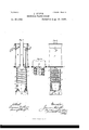
- Figures 1 and 2 are vertical sections at right angles to each other of my improved hot-water boiler; and Figs. 3 and 4, separate plans of parts of the boiler under the lines 8 3 and 4 4, respectively.
- Figs. 5 and 6 are vertical sections at right angles to each other of the improved boiler combined with a water heating and circulating tank, the tank in Fig. 6 being in elevation.
- Figs. 7 and 8 are vertical sections, and Fig. 9 is a horizontal section on the lineS 8 of the boiler combined with 'a modified form of tank.
- the boiler is composed of a series of superposed sections 0 communicating one with another through orifices formed at the corners where the sections are bolted together, each section circulating directly and independently into the said orifices, forming upright watercolumns communicating with the upper part of the boiler, the whole resting on a metal base 13, in which is loosely fitted a dumping fire-grate A; and the fire-chamber, which is entirely surrounded by a waterjacket 0, is formed by the two lowest sections 0 and O of the boiler.
- These sections are formed with rows of vertical corrugations surrounding the fire, excepting at part of the back, where a fire-brick D is inserted in a water-jacketed recess provided for it, and at the front, where the firing-door E and clinkerdoor E are fitted.
- the fire-box is made deeper, when desired, by the introduction of a. section similar to C, but without dooropenings, and with both top and lower edges perfectly horizontal between the lowest section 0 and the section 0,
- the upper edges or bearing-surfaces c of the water-jacketed fire-chamber are inclined from back to front, the extent of inclination being preferably about equal to the depth of one of the water-sections 0 above.
- These water-sections are in like manner inclined from back to front, their joints or meeting surfaces being also so inclined, excepting at front and back, where they are horizontal, and they are formed with cross-tubes 0 connecting the front and back, which, instead of being horizontal, are inclined.
- the sections 0 communicate with each other only at the four corners, (or at other like points, according to the configuration of the sections in plan,) where vertical flanged tubelike orifices C are formed, the flanges c be ing on the inside among the water and being faced up.
- a layer of asbestus, mill-board, or similar packing may be fitted at the joints when the sections are laid over each other in erecting the boiler.
- the heating apparatus is made, as shown in Figs. 1 and 2, in the form of aboiler without a separate water or steam vessel, there is placed over the uppermost section 0 an inclosed water-dome I, inclined at its lower face from back to front to fit the angle of the sections and the upper surface of the firechamber or lower sections, while the top of v the dome-section I is perfectly level.
- the top or cover of the dome is screw-pin and rust jointed to the lower part, a circulation being kept up through the depressed portion of dome I by the narrow cross-channel I.
- Cleaning or soot doors K are fitted between the several sections 0*, so that all parts of the heating-surfaces can be thoroughly and rapidly cleaned of dust or seat.
- the form of these soot-doors is shown more particularly in Figs. t and 8.
- a perforated distributing-plate L Over the uppermost tube-section O is loosely fitted a perforated distributing-plate L, preferably in two halves hinged together, to pre vent directontfiow of the hot products of combustion of the fuel.
- a long vertical or slightly-tapered chamber H through the center of which passes the chimney M, carrying off the products of combustion.
- This cylinder is, for convenience of access to the binding bolts .I, divided into two parts II and II, connected by a horizontal flanged joint 71, which is faced and kept perfectly level, the lower portion H being inelined and formed to fit the upper inclined section C immediately below it, and having tubular orifices in it communicating with the water-sections below and fitted with seats for bridges j, which form the bearings for the nuts 7" of the binding-bolts J, as shown in Figs. 6
- a dome-like diaphragm N is fitted, extending from the shell of the cylinder to within a short distance of the chimney-tube M, and leaving merely a narrow annular passage or for the upward and outward flow of the water round the tube M, in order that all the water may be forced to fiow over the diaphragm at this point, and that all the available heat of the chimney may be absorbed by the water.
- a steam-space O is also formed round the top part of the cylinder with an annular air-space 0 all round it.
- the outlet-pipe I for the water is connected to the water-cylinder II 011 the upper side of the diaphragm N, in which a pocket N is formed for draining into said pipes, and, it opens directly to the atmosphere, while the inlet-pipe Q for cold water is led in preferably at the back immediately below the diaphragm N, and is carried down through the water to the bottom of the cylinder II, or into the water-columns of the sec tion at the back to promote circulation and to partially heat the infiowing water, and thus lessen the risk of. injuring the sections of the boiler which are directly exposed to the fire.
- the inlet-pipe Q may be connected to the lower section C and the outlet-pipe I to the water-dome I, as shown in Fig. l; or more inlet and outlet pipes can be attached either by screwed or flanged joints to the parts mentioned, in the manner shown by openings and attachments. at Q and P 011 Figs. 2 and 3.
- the apparatus is used for generating steam at low pressure for cooking or heating purposes, a steam-cylinder 11 1 1", with domed top, as shown in Figs. 7, 8, and 9, takes the place of the water-cylinder II, the chimney fine M going through a stuffing-box m in the top of the steam-vessel.
- the steam demo or cylinder H is fitted with a safety-valve Z, water-gage Z,stean1-pipe Z and feed-watersupply pipe and valve Z the last being operated by a ball-lever Z, by means of which the normal water-level is uniformly maintained.
- Either water or steam cylinder may be jacketed or formed withadouble casing inclosin g air.
- each of the tubed sections is provided with a sunk screwed plug opposite the end of every tube at the back of the boiler, so that the inside of the tubes can be examined after the sections are formed.
- the boilers are used for heating water or for raising steam for washing or bathing or other purposes, and where the water isthus necessarily regularly drawn off or evaporated from theboilers,suitably-faced clean ing-doors are arranged at the corners of each section at each side of the dome and opposite the ends of every tube, back and front, for the purpose of enabling all the internal water-ways to be thoroughly and periodically cleaned of any sediment deposit formed from bad water.
Landscapes
- Engineering & Computer Science (AREA)
- Physics & Mathematics (AREA)
- Thermal Sciences (AREA)
- Chemical & Material Sciences (AREA)
- Combustion & Propulsion (AREA)
- Mechanical Engineering (AREA)
- General Engineering & Computer Science (AREA)
- Instantaneous Water Boilers, Portable Hot-Water Supply Apparatuses, And Control Of Portable Hot-Water Supply Apparatuses (AREA)
Description
. (No Model.) 3 Sheets-Sheet 1.
- J. KEIT SEGTIONAL WATE ILER. No. 409,042. Patented Aug. 13, 1889. F131; I F375 1 2* Q 1 mum 1 (No Model.) 3 Sheets-Sheet 2. J. KEITH.
SBGTIONAL WATER BOILER. No. 409,042. Patented Aug. 13, 1889.v
WVYLXIW 1 WWW c2 (No Model.) 3 Sheets-Sheet 3.
J. KEITH. v SEOTIONAL WATER BQILER.
No. 409,042. Patented Aug. 13 1889.
Fig"
fawn La :u. PETERS. MoLvthizgr-pher, wmm ngps'o UNITED STATES PATENT ()FFICE.
JAMES KEITH, OF LONDON, ENGLAND.
SECTIONAL WATER-BOILER.
SPECIFICATION forming part of Letters Patent No. 409,042, dated August 13, 1889. -Application filed December 13, 1888. Serial No. 298,523. (No model.) Patented in England May 9, 1885, No. 5,744.
To all whom, it Hwy concern:
Be it known that I, JAMES KEITH, a citizen of the United Kingdom of Great Britain and Ireland, residing at 57 Holborn Viaduct, in the city of London, England, have invented new and useful Improvements in Sectional I-Iot-VVater Boilers, which have not been patented in any country except Great Britain by Letters Patent dated the 9th day of May, 1885, No. 5,744; and I do hereby'declare that the following is a full, clear, and exact description of the invention, which will enable others skilled in the art or manufacture to which it relates to make and use the same.
My invention relates to sectional hot-water boilers of the type illustrated in the specification filed with my application, Serial No. 293,522, for patent of even date herewith; and it consists in features of novelty hereinafter fully described in connection with the accompanying drawings, and particularly pointed out in the claims.
In the said drawings, Figures 1 and 2are vertical sections at right angles to each other of my improved hot-water boiler; and Figs. 3 and 4, separate plans of parts of the boiler under the lines 8 3 and 4 4, respectively. Figs. 5 and 6 are vertical sections at right angles to each other of the improved boiler combined with a water heating and circulating tank, the tank in Fig. 6 being in elevation. Figs. 7 and 8 are vertical sections, and Fig. 9 is a horizontal section on the lineS 8 of the boiler combined with 'a modified form of tank.
The boiler is composed of a series of superposed sections 0 communicating one with another through orifices formed at the corners where the sections are bolted together, each section circulating directly and independently into the said orifices, forming upright watercolumns communicating with the upper part of the boiler, the whole resting on a metal base 13, in which is loosely fitted a dumping fire-grate A; and the fire-chamber, which is entirely surrounded by a waterjacket 0, is formed by the two lowest sections 0 and O of the boiler. These sections are formed with rows of vertical corrugations surrounding the fire, excepting at part of the back, where a fire-brick D is inserted in a water-jacketed recess provided for it, and at the front, where the firing-door E and clinkerdoor E are fitted. The fire-box is made deeper, when desired, by the introduction of a. section similar to C, but without dooropenings, and with both top and lower edges perfectly horizontal between the lowest section 0 and the section 0,
The upper edges or bearing-surfaces c of the water-jacketed fire-chamber are inclined from back to front, the extent of inclination being preferably about equal to the depth of one of the water-sections 0 above. These water-sections are in like manner inclined from back to front, their joints or meeting surfaces being also so inclined, excepting at front and back, where they are horizontal, and they are formed with cross-tubes 0 connecting the front and back, which, instead of being horizontal, are inclined.
The sections 0 communicate with each other only at the four corners, (or at other like points, according to the configuration of the sections in plan,) where vertical flanged tubelike orifices C are formed, the flanges c be ing on the inside among the water and being faced up. A layer of asbestus, mill-board, or similar packing may be fitted at the joints when the sections are laid over each other in erecting the boiler.
Then the heating apparatus is made, as shown in Figs. 1 and 2, in the form of aboiler without a separate water or steam vessel, there is placed over the uppermost section 0 an inclosed water-dome I, inclined at its lower face from back to front to fit the angle of the sections and the upper surface of the firechamber or lower sections, while the top of v the dome-section I is perfectly level. The top or cover of the dome is screw-pin and rust jointed to the lower part, a circulation being kept up through the depressed portion of dome I by the narrow cross-channel I.
The inclined tubular sections 0 the domepiece I, and the fire-chamber or lower corrugated ring-sections C andC are secured together by long bolts J, passingdown at the four corners through the orifices or water columns connecting the sections, as shown particularly in Figs. and &. These orifices or upright water-columns O, communicating with the dome or upper part and with each section separately, produce, in combination with the highly-inclined sections, an active and constant internal circulation when the boilers are heated, which equalizes the temperature of the water more readilyin all parts of the boiler and prevents the formation of steam in the cross-tubes and damage from undue expansion and contraction, besides making the whole more powerful and economical as a water-heater. Cleaning or soot doors K are fitted between the several sections 0*, so that all parts of the heating-surfaces can be thoroughly and rapidly cleaned of dust or seat. The form of these soot-doors is shown more particularly in Figs. t and 8. Over the uppermost tube-section O is loosely fitted a perforated distributing-plate L, preferably in two halves hinged together, to pre vent directontfiow of the hot products of combustion of the fuel.
In lieu of a simple dome, I in some cases fit over the sections 0 as shown in Figs. 5 and 6, a long vertical or slightly-tapered chamber H, through the center of which passes the chimney M, carrying off the products of combustion. This cylinder is, for convenience of access to the binding bolts .I, divided into two parts II and II, connected by a horizontal flanged joint 71, which is faced and kept perfectly level, the lower portion H being inelined and formed to fit the upper inclined section C immediately below it, and having tubular orifices in it communicating with the water-sections below and fitted with seats for bridges j, which form the bearings for the nuts 7" of the binding-bolts J, as shown in Figs. 6
and 9.
Near the top and inside of the cylinder II a dome-like diaphragm N is fitted, extending from the shell of the cylinder to within a short distance of the chimney-tube M, and leaving merely a narrow annular passage or for the upward and outward flow of the water round the tube M, in order that all the water may be forced to fiow over the diaphragm at this point, and that all the available heat of the chimney may be absorbed by the water. A steam-space O is also formed round the top part of the cylinder with an annular air-space 0 all round it. The outlet-pipe I for the water is connected to the water-cylinder II 011 the upper side of the diaphragm N, in which a pocket N is formed for draining into said pipes, and, it opens directly to the atmosphere, while the inlet-pipe Q for cold water is led in preferably at the back immediately below the diaphragm N, and is carried down through the water to the bottom of the cylinder II, or into the water-columns of the sec tion at the back to promote circulation and to partially heat the infiowing water, and thus lessen the risk of. injuring the sections of the boiler which are directly exposed to the fire. When the improved apparatus is employed for circulating hot water through watercoils and the like, the inlet-pipe Q may be connected to the lower section C and the outlet-pipe I to the water-dome I, as shown in Fig. l; or more inlet and outlet pipes can be attached either by screwed or flanged joints to the parts mentioned, in the manner shown by openings and attachments. at Q and P 011 Figs. 2 and 3.
\Vhen the apparatus is used for generating steam at low pressure for cooking or heating purposes, a steam-cylinder 11 1 1", with domed top, as shown in Figs. 7, 8, and 9, takes the place of the water-cylinder II, the chimney fine M going through a stuffing-box m in the top of the steam-vessel. The steam demo or cylinder H is fitted with a safety-valve Z, water-gage Z,stean1-pipe Z and feed-watersupply pipe and valve Z the last being operated by a ball-lever Z, by means of which the normal water-level is uniformly maintained. Either water or steam cylinder may be jacketed or formed withadouble casing inclosin g air. Ordinarily each of the tubed sections is provided with a sunk screwed plug opposite the end of every tube at the back of the boiler, so that the inside of the tubes can be examined after the sections are formed. IVhere, however, the boilers are used for heating water or for raising steam for washing or bathing or other purposes, and where the water isthus necessarily regularly drawn off or evaporated from theboilers,suitably-faced clean ing-doors are arranged at the corners of each section at each side of the dome and opposite the ends of every tube, back and front, for the purpose of enabling all the internal water-ways to be thoroughly and periodically cleaned of any sediment deposit formed from bad water.
I Iavingnow described myinvention, what I desire to claim and secure by Letters Patent 1s- 1. In a sectional boiler, the combination of the lower section 0, havinga fire-brick lining and a surrounding water-jacket, the superposed section 0, having inclined upper edges, and a number of superposed sections C hav ing inclined upper and lower edges, mounted on the section 0', and all of said sectionshavin g communicating openings, substantially as set forth.
2. In a sectional boiler, the combination, with the fire-chamber, of the superposed section C, having a water-space and inclined upper edges, the superposed sections C having vertical outer sides and inclined upper and lower edges mounted upon the section G, and having communication therewith and with each other, and inclined tubes 0 extending across each of said sections 0 substantially as and for the purposes set forth.
In a sectional boiler, the combination, with the firebox, of the superposed section 0,
having the Water-jacket e and inclined upper In witness whereof I have hereunto set my flanged edges, the superposed sections 0 hand this 22d day of October, 1888.
having inclined upper and lower edges and JAMES KEITH. 1 the upper edges having flanges to receive the WVitnesses: 5 section immediately above, inclined tubes 0 GEO. M. ORUIKSHANK,
extending across the sections 0 and a dome Fel. Inst. Pat. Agents, 62 St. Vincent Street, having inclined lower edges surmountin g said Glasgow.
sections 0 and all of said sections and dome WVALLAOE FAIRWEATHER, having communicating openings, substan- O. E. FeZ. Inst. Patent Agents, 62 St. Vmcent 1o tially as and for the purposes set forth. Street, Glasgow.
Publications (1)
| Publication Number | Publication Date |
|---|---|
| US409042A true US409042A (en) | 1889-08-13 |
Family
ID=2477979
Family Applications (1)
| Application Number | Title | Priority Date | Filing Date |
|---|---|---|---|
| US409042D Expired - Lifetime US409042A (en) | James keith |
Country Status (1)
| Country | Link |
|---|---|
| US (1) | US409042A (en) |
-
0
- US US409042D patent/US409042A/en not_active Expired - Lifetime
Similar Documents
| Publication | Publication Date | Title |
|---|---|---|
| US409042A (en) | James keith | |
| US681280A (en) | Steam-boiler. | |
| US425766A (en) | Trix of said avard s | |
| US661116A (en) | Hot-water heater. | |
| US465929A (en) | Steam-boiler | |
| US324314A (en) | Office | |
| US904138A (en) | Water-heating apparatus. | |
| US235684A (en) | Steam-boiler | |
| US374615A (en) | mckinlay | |
| US414297A (en) | Steam-generator | |
| US719224A (en) | Boiler. | |
| US635923A (en) | Steam-boiler. | |
| US441280A (en) | Upright tubular steam-boiler | |
| US240299A (en) | Steam-generator | |
| US352825A (en) | Steam-boiler | |
| US545376A (en) | petersen | |
| US193069A (en) | Improvement in steam-boilers | |
| US751453A (en) | Bromley | |
| US605410A (en) | Boiler | |
| US444802A (en) | van stone | |
| US601485A (en) | Island | |
| US393064A (en) | Steam-boiler | |
| US788068A (en) | Steam-boiler. | |
| US568438A (en) | Steam-boiler | |
| US359672A (en) | Boiler |