US4105723A - Vapor-liquid contacting - Google Patents
Vapor-liquid contacting Download PDFInfo
- Publication number
- US4105723A US4105723A US05/689,178 US68917876A US4105723A US 4105723 A US4105723 A US 4105723A US 68917876 A US68917876 A US 68917876A US 4105723 A US4105723 A US 4105723A
- Authority
- US
- United States
- Prior art keywords
- tray
- vapor
- liquid
- improvement
- stage
- Prior art date
- Legal status (The legal status is an assumption and is not a legal conclusion. Google has not performed a legal analysis and makes no representation as to the accuracy of the status listed.)
- Expired - Lifetime
Links
- 239000007788 liquid Substances 0.000 title claims abstract description 179
- 230000010355 oscillation Effects 0.000 claims abstract description 14
- 239000011148 porous material Substances 0.000 claims description 13
- 239000002184 metal Substances 0.000 claims description 11
- 238000000034 method Methods 0.000 claims description 5
- 230000008569 process Effects 0.000 claims description 5
- 239000006185 dispersion Substances 0.000 claims 15
- 238000000926 separation method Methods 0.000 claims 1
- 239000003999 initiator Substances 0.000 abstract description 6
- 238000010276 construction Methods 0.000 abstract description 3
- 230000008878 coupling Effects 0.000 abstract description 3
- 238000010168 coupling process Methods 0.000 abstract description 3
- 238000005859 coupling reaction Methods 0.000 abstract description 3
- 239000012530 fluid Substances 0.000 description 5
- 230000037452 priming Effects 0.000 description 5
- 230000008901 benefit Effects 0.000 description 4
- 239000010410 layer Substances 0.000 description 4
- 239000007921 spray Substances 0.000 description 4
- 230000009467 reduction Effects 0.000 description 3
- XLYOFNOQVPJJNP-UHFFFAOYSA-N water Substances O XLYOFNOQVPJJNP-UHFFFAOYSA-N 0.000 description 3
- 230000015572 biosynthetic process Effects 0.000 description 2
- 238000003889 chemical engineering Methods 0.000 description 2
- 238000004581 coalescence Methods 0.000 description 2
- 230000000694 effects Effects 0.000 description 2
- 238000004508 fractional distillation Methods 0.000 description 2
- 239000012634 fragment Substances 0.000 description 2
- 230000005484 gravity Effects 0.000 description 2
- 239000000463 material Substances 0.000 description 2
- 239000011159 matrix material Substances 0.000 description 2
- 239000000203 mixture Substances 0.000 description 2
- 230000001133 acceleration Effects 0.000 description 1
- 238000005273 aeration Methods 0.000 description 1
- 150000001338 aliphatic hydrocarbons Chemical class 0.000 description 1
- 238000013459 approach Methods 0.000 description 1
- 230000009286 beneficial effect Effects 0.000 description 1
- 230000001413 cellular effect Effects 0.000 description 1
- 230000005465 channeling Effects 0.000 description 1
- 239000012141 concentrate Substances 0.000 description 1
- 230000003247 decreasing effect Effects 0.000 description 1
- 239000006260 foam Substances 0.000 description 1
- 230000002706 hydrostatic effect Effects 0.000 description 1
- 239000003208 petroleum Substances 0.000 description 1
- 230000000630 rising effect Effects 0.000 description 1
- 239000002356 single layer Substances 0.000 description 1
- 229910001220 stainless steel Inorganic materials 0.000 description 1
- 239000010935 stainless steel Substances 0.000 description 1
- 230000007704 transition Effects 0.000 description 1
- 238000009736 wetting Methods 0.000 description 1
Images


Classifications
-
- B—PERFORMING OPERATIONS; TRANSPORTING
- B01—PHYSICAL OR CHEMICAL PROCESSES OR APPARATUS IN GENERAL
- B01D—SEPARATION
- B01D3/00—Distillation or related exchange processes in which liquids are contacted with gaseous media, e.g. stripping
- B01D3/14—Fractional distillation or use of a fractionation or rectification column
- B01D3/16—Fractionating columns in which vapour bubbles through liquid
- B01D3/22—Fractionating columns in which vapour bubbles through liquid with horizontal sieve plates or grids; Construction of sieve plates or grids
-
- B—PERFORMING OPERATIONS; TRANSPORTING
- B01—PHYSICAL OR CHEMICAL PROCESSES OR APPARATUS IN GENERAL
- B01D—SEPARATION
- B01D3/00—Distillation or related exchange processes in which liquids are contacted with gaseous media, e.g. stripping
- B01D3/14—Fractional distillation or use of a fractionation or rectification column
- B01D3/32—Other features of fractionating columns ; Constructional details of fractionating columns not provided for in groups B01D3/16 - B01D3/30
Definitions
- This invention relates to vapor-liquid contacting in apparatus of the cross-flow type, e.g., in a fractional distillation column.
- drilling is used herein in its broad sense to encompass (a) the jetting of liquid from one tray up into the next, often referred to as “priming”; (b) so-called “downcomer flooding", which occurs when the liquid head is insufficient to cause liquid to exit through the downcomer, either because liquid density has been decreased by gas entrainment, or because pressure drop across the tray is too high; and (c) excessive entrainment of liquid droplets by vapor flow at the tray orifices and in the froth.
- flooding limits superficial gas velocity and hence column throughput. For a given throughput, flooding also imposes column stage height requirements.
- the particular type of flooding responsible for these limitations depends upon the system being processed.
- L and G are liquid and vapor flow rates, respectively, and ⁇ l and ⁇ g are liquid and vapor densities, respectively
- entrainment tends to be the limiting factor
- priming and downcomer flodding become dominant.
- Liquid entrainment also limits the ability to use low liquid flow rates along the tray, since that flow rate must be kept substantially above the entrainment rate to maintain an effective liquid head on the tray. High entrainment rates also lower plate efficiency.
- the invention makes possible unusually high superficial gas velocity through a given column without flooding, substantially increasing column throughput.
- the benefit of this aspect of the invention may be taken by way of reduced column stage height.
- unusually low liquid flow rates without excessive entrainment are made possibel over a wide range of gas velocities.
- the invention provides an improved froth initiator, of simple and inexpensive construction, at the liquid inlet end of the tray.
- the invention provides improved means for de-entraining vapor from liquid passing to the stage below.
- the invention provides improved means for de-entraining liquid from vapor passing to the stage above.
- the invention features raising the flooding point by providing a multiplicity of spaced, generally vertical baffles above the tray, the baffles extending generally in the direction of liquid flow across the tray and being sufficiently close together to substantially reduce the amplitude of vertical fluid oscillations having a wavelength which is small relative to the width of said tray, and increasing the superficial vapor velocity to above the flooding-limited maximum permissible velocity associated with the column in the absence of the baffles.
- the baffling is used in conjunction with column stage height below the flooding-limited height associated with the stage in the absence of the baffles.
- the invention features reducing liquid entrainment with the same baffles, and reducing the rate of liquid flow along the tray to below the entrainment-limited minimum associated with the tray in the absence of the baffles.
- the invention features means mounted beneath the tray to form a flow resistance sufficiently close to the underside of the tray to substantially reduce pressure coupling between the underside of the tray and the main volume of vapor beneath the tray, whereby the minimum permissible vapor velocity and the dumping point are correspondingly lowered.
- the invention features an impingement type separator mounted above the tray (and, where used in conjunction with the baffling, above the baffles), in the path of vapor passing to the stage above, the separator having its major surfaces tilted at 45°-75° to the horizontal and extending generally parallel to the direction of liquid flow along the tray. Under conditions where priming is not a factor, the separator by itself will raise the flood point to permit increased throughput, reduced stage height, or low liquid flow rate.
- the invention features a special porous separator mounted in the path of liquid flow to the tray below and arranged to preferentially retard vapor bubbles.
- the invention also features an improved froth initiator comprising an inlet weir sloping from the bottom of the liquid downcomer upwardly in the direction of liquid flow along the tray and extending over vapor openings in the tray through which vapor passes from the stage below, the weir and the downcomer apron being arranged relative to each other so as to cause liquid to enter the stage in a thin sheet into froth which is propelled in the direction of liquid flow by said vapor entering beneath said weir and deflected downstream thereby.
- the invention also features certain special baffle constructions.
- the baffles are spaced apart less than 4 inches plus half the height of the outlet weir (the space most preferably being less thant 21/2 inches); baffle height is at least as great as the average baffle-to-baffle spacing;
- the impingement type separator is a zigzag arrangement, preferably of porous mesh, extending generally across the stage and having its vertices generally parallel to the direction of liquid flow along the tray;
- the porous separator for vapor de-entrainment is mounted in a liquid downcomer and consists of a screen or mesh, preferably pleated and sloping downwardly and outwardly, with special baffling provided above the separator to enhance the upward return of vapor;
- the means mounted beneath the tray to lower the dumping point is a perforated plate (with its holes misaligned with those of the tray and with the spacing between the tray and the plate being no less than 1/4 the average diameter of the holes in the plate) spaced beneath the tray of a porous mesh (having a flow resistance
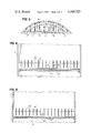
- FIG. 1 is a semi-schematic, fragmentary, vertial sectional view of one stage of a fractional distillation column embodying the invention
- FIG. 2 is a sectional view taken along 2--2 of FIG. 1;
- FIG. 3 is a sectional view taken along 3--3 of FIG. 1;
- FIG. 4 is a fragmentary sectional view similar to FIG. 2 showing another embodiment of the invention.
- FIG. 5 is a fragmentary sectional view similar to FIG. 4, showing another embodiment of the invention.
- FIG. 6 is a sectional view similar to FIG. 3 showing another embodiment
- FIG. 7 is a fragment of a sectional view similar to FIGS. 2 and 5 showing another embodiment.
- FIG. 8 is a fragment of a view similar to FIG. 1 showing another embodiment.
- cylindrical housing 10 of liquid-vapor contacting and separating column 12 has a conventional central vapor inlet and reboiler (not shown) below its bottom stage.
- a series of contact stages is vertically arranged inside housing 10.
- a plate 22 extends across housing 10.
- the downcomer 32 from the tray above carries liquid from the tray above into seal pan 33 with base 34.
- the liquid flows under downcomer apron 35 and over forward sloping inlet weir 23 (which preferably extends above apron 35) onto the active portion of tray 22 between the base of the inlet weir and vertical outlet weir 24.
- the clearance between the downcomer apron and the inlet weir (1/4 inch as shown, with a preferred range of 1/16 to 1 inch, the preferred clearance being smaller for lower liquid flow rates), and the forward tilt of the inlet weir (60° to the horizontal as shown with a preferred range of 30° to 75°), are such as to cause the liquid to enter the tray as a relatively thin sheet with a forward and upward thrust.
- the active section of plate 22 between inlet weir 23 and outlet weir 24 is perforated with holes 25, 1/2 inch in diameter on 1.2 inch square centers in the embodiment shown.
- the area of the holes thus amounts to 13.7% of the total area of the active section of the plate.
- the plate free area should be chosen to be high enough so as not to give an unacceptably high plate pressure drop at design throughput, but not to be so high as to lead to excessive weeping at turndown.
- the inlet region configuration acts to promote rapid aeration of the incoming liquid without weeping, since the thin liquid sheet is introduced by sloping weir 23 into a body of aerated froth which is propelled down the plate by vapor entering from beneath weir 23 and deflected downstream by its sloping undersurface.
- the configuration also serves to quickly carry incoming liquid away from the inlet region.
- baffles 26 are located above the plate to limit and damp fluid oscillations by subdivision of the froth. These baffles 26 run in the direction of liquid flow across the plate, are about 3 inches high, and are spaced across the plate.
- the baffles may be made of expanded metal and located directly on the plate while still permitting some transverse liquid flow to equalize minor head differences which may develop.
- the baffles are spaced on 1.5 inch centers at the center of the plate, and are more closely spaced at the inlet and outlet, being slightly angled or curved to match the widening of the liquid flow area at the center of the plate.
- baffles prevent formation of large scale non-uniformities in the flow of liquid across the plate, and also enable a closer realization of the increase in plate efficiency over point efficiency due to the cross-flow effect by minimizing liquid eddying, backmixing, channeling, and bypassing.
- the primary function of the baffles in the present invention is the reduction of amplitude of vertical fluid oscillations having a wavelength which is small relative to the width of the tray.
- amplitude of vertical fluid oscillations having a wavelength which is small relative to the width of the tray is small relative to the width of the tray.
- the baffles reduce entrainment and increase the flooding limit for the tray in several ways: (1) By limiting the amplitude of fluid oscillations, they increase froth density and reduce froth height, thereby increasing the superficial gas velocity and F number (defined in said prior patent) attainable before the froth impacts, and is carried up into, the tray above (priming). (2) They increase the superficial gas velocity and F number at which transition from froth to spray regime operation occurs (advantageous, since for given operating conditions, spray regime operation tends to generate considerably higher entrainment rates and lower efficiencies than froth regime operation, making the froth regime far preferably for operation).
- Baffle spacing should in general be less than 4 inches plus 1/2 the outlet weir height for the baffles to be effective in limiting vertical oscillations. For most systems, the optimum baffle spacing will be less than 21/2 inches. Baffle height should in general be equal to or greater than the average baffle center-to-center spacing.
- the preferred embodiment shown also includes, downstream of the tray and baffles, a vapor-liquid separator means of the impingement type in the form of one or more spaced layers of open cellular material 40, pleated or folded in aigzag fashion and disposed generally parallel to plate 22 across the vapor flow path, with the vertices of the zigzag folds generally parallel to the direction of liquid flow across the plate.
- the pleats or folds extend at an angle of approximately 60° to the horizontal, although this may vary from 45° to 75°.
- a single layer is used, consisting of a sheet of expanded metal with six plies of woven wire mesh on top of the expanded metal.
- the zigzag pattern generates a vapor flow area significantly greater than the superficial column cross-section.
- the reduced velocity of the vapor normal to the expanded metal and mesh surfaces (due to the zigzag pattern) makes for more effective de-entrainment and makes reentrainment less likely.
- the steep slope of the mesh and expanded metal sections gives a gravitational force for liquid drainage down the sides of the mesh and expanded metal of 0.87 times the force of gravity and results in efficient drainage down the sides of the separator to the base of the zigzag vees and from there back to the plate.
- the separator also contributes significantly to plate mass transfer, particularly at higher vapor rates where the liquid flow rate into the separator is large, efficiency increasing as superficial gas velocity approaches the flood point.
- the separator may consist of chevron type baffles extending parallel to the direction of liquid flow along the plate, or other equivalent structures similarly having their major surfaces extending in the liquid flow direction and being at an angle of 45°-75° to the horizontal to minimize gas phase pressure drop. Under conditions where priming is not a factor, the separator by itself will raise the flood point to permit increased throughput, reduced stage height, or low liquid flow rate.
- the screen is crimped into a zigzag pattern as shown in FIG. 3 to increase its surface area and thereby reduce liquid pressure drop across it and fractional blockage of it by vapor bubbles.
- the vapor bubbles will tend to coalesce toward the bottom of the sloping screen and rise up behind baffle 52 (which separates a vapor return zone 53 from the liquid downflow zone 54) due to hydrostatic forces generated by the lower froth density resulting from the bubble concentration and due to the larger diameter of the coalesced bubbles and rejoin the vapor rising to the plate above.
- This screen and baffle arrangement in the downcomer therefore de-entrains vapor and increases the density of the mixture in the downcomer which increases permissible throughputs with a fixed stage height or enables a reduction in stage height with a given throughput before downcomer flooding limits are reached.
- This is particularly apt to be beneficial in high pressure towers such as the light ends towers in a petroleum refinery where the vapor density is high, the difference between liquid and vapor density relatively small, the surface tension low, and the throughputs high. These conditions favor the entrainment of the vapor in the downcomer liquid as a fine-bubble, slow-rising foam, make the vapor difficult to de-entrain, and make this regime one likely to be downcomer flooding limited.
- baffles 56 are distributed through the downcomer above screen 50.
- Those baffles 56 near the outlet weir are preferably V-shaped with their vertices pointing toward the tray.
- These baffles help remove entrained vapor in two ways. First, as liquid flows horizontally past the V-shaped baffles, the V-shape separates the flow, producing a low pressure region in zone 57 behind each baffle where the vapor concentrates and rises. Second, oscillating bubbles in general tend to move toward a wall, so that even in the absence of a horizontal liquid flow, component vapor should collect along the baffle walls and rise.
- a vapor coalescing mesh may be used instead of screen 50.
- such mesh may be placed on top of the screen. The mesh should stimulate coalescence of vapor bubbles because of preferential wetting and drag which will distort and increase the interfacial area, increasing the likelihood of collision between vapor bubbles and coalescence.
- FIGS. 4 and 5 show other embodiments in which the baffles of FIGS. 1-3 are optionally used.
- the active section of plate 22' between inlet weir 23 and outlet weir 24 is perforated with 1/2 inch diameter holes 25' on 3/4 inch centers.
- the area of the holes amounts to 35% of the total active area of the plate.
- Spaced 3/16 inch below plate 22' is a similar plate 60 also perforated with 1/2 inch holes 25a on 3/4inch centers.
- the holes in the two plates are preferably misaligned so that no vertical path directly down through both sets of holes exists.
- the lower plate acts as a flow resistance and is sufficiently close to the underside of the main plate to substantially reduce pressure coupling between the underside of the tray and the main volume of vapor beneath the tray, whereby the minimum permissible vapor velocity and the dumping point are correspondingly lowered.
- the space between these plates acts as a capacitance zone which is in series with the two flow resistances formed by the holes in the two plates.
- the staggering of the plate holes not only blocks pressure fluctuation transmittal, but also leads to the deentrainment of droplets from the gas flow by impact on the bottom of the upper plate as the upper plate deflects the flow of gas through the holes in the lower plate. Deentrained droplets coalesce into films as they impact, and the liquid drips back to the plate from which it was entrained as the films grow.
- the flow resistance of the bottom plate is comparable to or larger than that of the top plate, the dominant flow capacitance affecting pressure fluctuations at the holes in the top plate will be based on the chamber volume between the plates.
- the flow capacitance between the two plates may be represented by the dimensionless number:
- V c the active chamber volume between the plates
- a o the total open area of the top plate
- the amplitude of pressure fluctuations beneath the top plate may be kept small and the frequency of these fluctuations high by maintaining the spacing between the plates small. Since weeping is less likely if the pressure deviations below the mean are small and of limited duration, the flow capacitance zone can significantly lower the tendency of a bubble plate to weep. From the dimensionless capacitance number, it is apparent that as pressure is reduced, chamber volume must also be reduced if the capacitance number is to be kept below a given value.
- the double plate configuration which makes the chamber volume small is therefore most apt to be required (to enable operation with low hole F numbers without weeping) in low pressure operation where low pressure drop is apt to be of critical importance and where low hole velocities are necessary to avoid spray regime operation and high entrainment which would otherwise be produced by low heads and high gas velocities for a given F number.
- the spacing between the plates should be no less than (and not much greater than) 1/4 the average diameter of the perforations in the lower plate, so that the flow resistance between the plates will be no greater than the flow resistance of the lower plate.
- the double plate introduces an impedance mismatch between the volume beneath the plates and that contained between the plates and prevents the transmittal of lower frequency, larger scale pressure fluctuations into and through the space between the plates.
- results similar to those obtained with the double plate configuration may be obtained by placing a suitable porous matrix material beneath plate 22" instead of a second plate.
- the porous material 70 e.g., eight layers of stainless steel mesh totalling 1/4 inches thick
- the porous material 70 is in contact with the underside of plate 22" and has a flow resistance not substantially less than that of the plate itself in a sufficiently limited depth so that the flow capacitance of the porous material is sufficiently small. This material will reduce the amplitude of pressure fluctuations under the plate and increase their frequency in a manner similar to that of the double plate configuration.
- FIGS. 4 and 5 represent alternative, and greatly improved, ways of achieving the high free tray area (e.g., 15%-55%), low pressure drop, and low dump point advantages of the structures claimed in said prior U.S. Pat. No. 3,887,665 without the disadvantages of, e.g., the hydraulic gradient in the liquid on the plate which inherently results from the porous matrix located as disclosed in that patent.
- the froth initiator of FIGS. 1 and 2 is particularly useful in low pressure drop, high free tray area systems such as those of FIGS. 4 and 5, particularly when operated near the turndown point, since it prevents the buildup of excessive unaerated liquid head at the inlet region.
- FIGS. 1-5 Although the invention has been illustrated in FIGS. 1-5 in connection with a perforated plate tray, it is also applicable to other types of orificed trays, such as, e.g., valves.
- FIGS. 7 and 8 show special forms of baffles for use as baffles 26, 26', and 26" of FIGS. 2, 4 and 5.
- a 1/4 inch layer of mesh (wettable by the liquid of the system being processed) 80 is placed in contact with each side of each baffle 82.
- the mesh increases the thickness of the layer of vapor-free liquid adjacent the baffles and thereby induces a greater return flow of liquid to the plate at the baffles, increasing froth density, improving vapor-liquid disengagement, and reducing froth height, thereby increasing the maximum permissible vapor and liquid flows before flooding conditions are reached.
- directional plate orifices or other conventional means may be used.
- baffles 90 have corrugations 92 sloping downward and in the direction of liquid flow across the plate. These corrugations provide flow channels which will tend to return vapor-free liquid to the plate.
- the mesh of FIG. 7 can be crimped and oriented to preferentially drain liquid downward and in the direction of liquid flow.
Landscapes
- Chemical & Material Sciences (AREA)
- Chemical Kinetics & Catalysis (AREA)
- Vaporization, Distillation, Condensation, Sublimation, And Cold Traps (AREA)
- Treating Waste Gases (AREA)
- Physical Or Chemical Processes And Apparatus (AREA)
Priority Applications (9)
| Application Number | Priority Date | Filing Date | Title |
|---|---|---|---|
| US05/689,178 US4105723A (en) | 1976-05-24 | 1976-05-24 | Vapor-liquid contacting |
| CA278,826A CA1097565A (en) | 1976-05-24 | 1977-05-19 | Vapour-liquid contacting |
| GB21459/77A GB1585771A (en) | 1976-05-24 | 1977-05-20 | Vapour liquid contacting |
| IT68168/77A IT1083580B (it) | 1976-05-24 | 1977-05-23 | Procedimento e dispositivo per la esecuzione di distillazioni frazionate e di simili porcessi di contatto vapore liquido |
| NL7705711A NL7705711A (nl) | 1976-05-24 | 1977-05-24 | Inrichting voor het met elkaar in contact bren- gen van damp en vloeistof. |
| DE19772723393 DE2723393A1 (de) | 1976-05-24 | 1977-05-24 | Verfahren und vorrichtung zum inkontaktbringen von dampf und fluessigkeit |
| JP6034577A JPS537575A (en) | 1976-05-24 | 1977-05-24 | Vaporrliquid contact system and its apparatus |
| FR7715847A FR2352572A1 (fr) | 1976-05-24 | 1977-05-24 | Perfectionnements aux procedes et aux appareillages a contact vapeur-liquide |
| US05/801,577 US4132761A (en) | 1976-05-24 | 1977-05-31 | Gas-liquid contacting |
Applications Claiming Priority (1)
| Application Number | Priority Date | Filing Date | Title |
|---|---|---|---|
| US05/689,178 US4105723A (en) | 1976-05-24 | 1976-05-24 | Vapor-liquid contacting |
Related Child Applications (1)
| Application Number | Title | Priority Date | Filing Date |
|---|---|---|---|
| US05/801,577 Continuation-In-Part US4132761A (en) | 1976-05-24 | 1977-05-31 | Gas-liquid contacting |
Publications (1)
| Publication Number | Publication Date |
|---|---|
| US4105723A true US4105723A (en) | 1978-08-08 |
Family
ID=24767360
Family Applications (2)
| Application Number | Title | Priority Date | Filing Date |
|---|---|---|---|
| US05/689,178 Expired - Lifetime US4105723A (en) | 1976-05-24 | 1976-05-24 | Vapor-liquid contacting |
| US05/801,577 Expired - Lifetime US4132761A (en) | 1976-05-24 | 1977-05-31 | Gas-liquid contacting |
Family Applications After (1)
| Application Number | Title | Priority Date | Filing Date |
|---|---|---|---|
| US05/801,577 Expired - Lifetime US4132761A (en) | 1976-05-24 | 1977-05-31 | Gas-liquid contacting |
Country Status (8)
| Country | Link |
|---|---|
| US (2) | US4105723A (it) |
| JP (1) | JPS537575A (it) |
| CA (1) | CA1097565A (it) |
| DE (1) | DE2723393A1 (it) |
| FR (1) | FR2352572A1 (it) |
| GB (1) | GB1585771A (it) |
| IT (1) | IT1083580B (it) |
| NL (1) | NL7705711A (it) |
Cited By (36)
| Publication number | Priority date | Publication date | Assignee | Title |
|---|---|---|---|---|
| US4156705A (en) * | 1977-06-23 | 1979-05-29 | Nippon Kokan Kabushiki Kaisha | Inclined screen tray tower |
| US4301098A (en) * | 1980-01-30 | 1981-11-17 | Mix Thomas W | Vapor liquid contacting |
| US4304738A (en) * | 1979-10-15 | 1981-12-08 | Nutter Dale E | Packing Material and apparatus |
| US4556522A (en) * | 1984-05-09 | 1985-12-03 | Air Products And Chemicals, Inc. | Sieve type distillation tray with curved baffles |
| US5091060A (en) * | 1990-09-10 | 1992-02-25 | Phillips Petroleum Company | Fractional distillation column and method for its use |
| US5096578A (en) * | 1990-08-15 | 1992-03-17 | Texaco Inc. | Vortex breaker for horizontal liquid draw off tray sump |
| US5269976A (en) * | 1991-11-14 | 1993-12-14 | The Boc Group, Plc | Liquid-vapour contact columns |
| US5368785A (en) * | 1992-05-27 | 1994-11-29 | Hamon-Sobelco S.A. | Anti-freezing device for cross-flow tower coolers |
| US5525271A (en) * | 1994-10-27 | 1996-06-11 | The Boc Group, Inc. | Liquid-vapor contact device |
| US5591241A (en) * | 1993-07-19 | 1997-01-07 | The Boc Group Plc | Liquid vapor contact apparatus |
| US5762668A (en) * | 1996-07-24 | 1998-06-09 | Glitsch, Inc. | Apparatus and method for deentrainment in a chemical process tower |
| US5795369A (en) * | 1996-03-06 | 1998-08-18 | Ceco Filters, Inc. | Fluted filter media for a fiber bed mist eliminator |
| US5895608A (en) * | 1996-10-30 | 1999-04-20 | Koch Enterprises, Inc. | Downcomer for chemical process tower and method of forming the same |
| US5948211A (en) * | 1990-02-06 | 1999-09-07 | Koch-Glitsch, Inc. | Distillation column downcomer having liquid permeable wall |
| US6293528B1 (en) * | 1998-04-23 | 2001-09-25 | Uop Llc | Fractionation apparatus with low surface area grid above tray deck |
| US6588735B2 (en) * | 2000-02-16 | 2003-07-08 | Shell Oil Company | Gas-liquid tray |
| EP1378281A1 (de) * | 2002-07-05 | 2004-01-07 | JULIUS MONTZ GmbH | Bodenkolonne |
| US7025336B2 (en) | 2003-09-03 | 2006-04-11 | Wynn Ii Richard | Apparatus for removing particulates from a gas stream |
| US20070145611A1 (en) * | 2005-12-23 | 2007-06-28 | Lee Adam T | Gas-liquid contactor baffle |
| US20080150171A1 (en) * | 2006-12-22 | 2008-06-26 | Amt International, Inc. | Gas-liquid contact apparatus |
| US20080156746A1 (en) * | 2006-12-14 | 2008-07-03 | Ludovic Raynal | Deflecting system for column trays |
| US20080179766A1 (en) * | 2007-01-30 | 2008-07-31 | Lee Adam T | Gas-liquid contact apparatus |
| US20080314729A1 (en) * | 2007-02-23 | 2008-12-25 | Exxonmobil Research And Engineering Company Law Department | Core de-entrainment device for vessels with tangential inlets |
| RU2342181C1 (ru) * | 2007-07-23 | 2008-12-27 | Открытое Акционерное Общество "Научно-Исследовательский И Проектный Институт Карбамида И Продуктов Органического Синтеза" (Оао Ниик) | Переливное устройство контактной тарелки и контактная тарелка |
| US20090189301A1 (en) * | 2008-01-24 | 2009-07-30 | Amt International, Inc. | Downcomer distributor |
| US20150129410A1 (en) * | 2013-09-12 | 2015-05-14 | Gradiant Corporation | Systems including a condensing apparatus such as a bubble column condenser |
| US10143936B2 (en) | 2015-05-21 | 2018-12-04 | Gradiant Corporation | Systems including an apparatus comprising both a humidification region and a dehumidification region with heat recovery and/or intermediate injection |
| US10143935B2 (en) | 2015-05-21 | 2018-12-04 | Gradiant Corporation | Systems including an apparatus comprising both a humidification region and a dehumidification region |
| US10294123B2 (en) | 2016-05-20 | 2019-05-21 | Gradiant Corporation | Humidification-dehumidification systems and methods at low top brine temperatures |
| US10376810B2 (en) | 2008-03-20 | 2019-08-13 | Gtc Technology Us Llc | Fluid dispersion unit with directional component vector |
| US10463985B2 (en) | 2015-05-21 | 2019-11-05 | Gradiant Corporation | Mobile humidification-dehumidification desalination systems and methods |
| US10513445B2 (en) | 2016-05-20 | 2019-12-24 | Gradiant Corporation | Control system and method for multiple parallel desalination systems |
| US10981082B2 (en) | 2015-05-21 | 2021-04-20 | Gradiant Corporation | Humidification-dehumidification desalination systems and methods |
| US20210299589A1 (en) * | 2014-08-11 | 2021-09-30 | Sulzer Management Ag | Method and system for orifice control of valve pressure drop |
| US11958001B2 (en) | 2014-08-11 | 2024-04-16 | Sulzer Management Ag | Method and system for orifice control of valve pressure drop |
| US12023608B2 (en) | 2016-01-22 | 2024-07-02 | Gradiant Corporation | Hybrid desalination systems and associated methods |
Families Citing this family (13)
| Publication number | Priority date | Publication date | Assignee | Title |
|---|---|---|---|---|
| JPS54153773A (en) * | 1978-05-26 | 1979-12-04 | Hitachi Ltd | Perforated barrier plate |
| JPS59134031U (ja) * | 1983-02-25 | 1984-09-07 | 日立金属株式会社 | 鋳物砂用温度測定センサ− |
| JPS59210289A (ja) * | 1984-04-23 | 1984-11-28 | 株式会社日立製作所 | 気液接触装置 |
| AU1540592A (en) * | 1991-02-26 | 1992-09-15 | Groundwater Technology, Inc. | Water remediation |
| KR940009563B1 (ko) * | 1992-09-04 | 1994-10-15 | 대우전자주식회사 | 식기 세척기 |
| US5259996A (en) * | 1992-12-14 | 1993-11-09 | Morgan Thomas H | Low profile cascade aerator |
| US6250611B1 (en) | 1999-10-07 | 2001-06-26 | Sulzer Chemtech Usa, Inc. | Vapor-liquid contact apparatus |
| US6575438B2 (en) | 2001-06-13 | 2003-06-10 | Sulzer Chemtech Usa, Inc. | Stepped downcomer apparatus and vapor-liquid contact apparatus with same |
| US6565071B2 (en) * | 2001-10-11 | 2003-05-20 | Amt International, Inc. | Liquid/gas contacting apparatus |
| FR2936717A1 (fr) * | 2008-10-07 | 2010-04-09 | Air Liquide | Distributeur de liquide |
| US9192895B2 (en) | 2012-03-27 | 2015-11-24 | Meurer Research Inc. | Cascade aerator assembly |
| FR2989594B1 (fr) * | 2012-04-18 | 2015-04-24 | IFP Energies Nouvelles | Plateau distributeur pour colonne de contact gaz/liquide offshore |
| FR2989595B1 (fr) * | 2012-04-18 | 2014-04-11 | IFP Energies Nouvelles | Plateau distributeur a cloisons pour colonne de contact gaz/liquide offshore |
Citations (4)
| Publication number | Priority date | Publication date | Assignee | Title |
|---|---|---|---|---|
| US3282576A (en) * | 1962-09-06 | 1966-11-01 | Union Carbide Corp | Apparatus for improved liquidvapor contact |
| US3712595A (en) * | 1971-07-12 | 1973-01-23 | A Hirsch | Upflow distributive trays for fractionating columns and absorption towers |
| US3765659A (en) * | 1972-01-17 | 1973-10-16 | B Reilly | Gas scrubber |
| US3887665A (en) * | 1973-04-20 | 1975-06-03 | Thomas William Mix | Vapor-liquid contacting |
Family Cites Families (1)
| Publication number | Priority date | Publication date | Assignee | Title |
|---|---|---|---|---|
| US3653812A (en) * | 1969-07-18 | 1972-04-04 | Wellman Lord Inc | Process for removal of sulfur dioxide from gas streams |
-
1976
- 1976-05-24 US US05/689,178 patent/US4105723A/en not_active Expired - Lifetime
-
1977
- 1977-05-19 CA CA278,826A patent/CA1097565A/en not_active Expired
- 1977-05-20 GB GB21459/77A patent/GB1585771A/en not_active Expired
- 1977-05-23 IT IT68168/77A patent/IT1083580B/it active
- 1977-05-24 NL NL7705711A patent/NL7705711A/xx not_active Application Discontinuation
- 1977-05-24 FR FR7715847A patent/FR2352572A1/fr not_active Withdrawn
- 1977-05-24 DE DE19772723393 patent/DE2723393A1/de not_active Withdrawn
- 1977-05-24 JP JP6034577A patent/JPS537575A/ja active Pending
- 1977-05-31 US US05/801,577 patent/US4132761A/en not_active Expired - Lifetime
Patent Citations (4)
| Publication number | Priority date | Publication date | Assignee | Title |
|---|---|---|---|---|
| US3282576A (en) * | 1962-09-06 | 1966-11-01 | Union Carbide Corp | Apparatus for improved liquidvapor contact |
| US3712595A (en) * | 1971-07-12 | 1973-01-23 | A Hirsch | Upflow distributive trays for fractionating columns and absorption towers |
| US3765659A (en) * | 1972-01-17 | 1973-10-16 | B Reilly | Gas scrubber |
| US3887665A (en) * | 1973-04-20 | 1975-06-03 | Thomas William Mix | Vapor-liquid contacting |
Cited By (48)
| Publication number | Priority date | Publication date | Assignee | Title |
|---|---|---|---|---|
| US4156705A (en) * | 1977-06-23 | 1979-05-29 | Nippon Kokan Kabushiki Kaisha | Inclined screen tray tower |
| US4304738A (en) * | 1979-10-15 | 1981-12-08 | Nutter Dale E | Packing Material and apparatus |
| US4301098A (en) * | 1980-01-30 | 1981-11-17 | Mix Thomas W | Vapor liquid contacting |
| US4556522A (en) * | 1984-05-09 | 1985-12-03 | Air Products And Chemicals, Inc. | Sieve type distillation tray with curved baffles |
| US5948211A (en) * | 1990-02-06 | 1999-09-07 | Koch-Glitsch, Inc. | Distillation column downcomer having liquid permeable wall |
| US5096578A (en) * | 1990-08-15 | 1992-03-17 | Texaco Inc. | Vortex breaker for horizontal liquid draw off tray sump |
| US5091060A (en) * | 1990-09-10 | 1992-02-25 | Phillips Petroleum Company | Fractional distillation column and method for its use |
| US5269976A (en) * | 1991-11-14 | 1993-12-14 | The Boc Group, Plc | Liquid-vapour contact columns |
| US5368785A (en) * | 1992-05-27 | 1994-11-29 | Hamon-Sobelco S.A. | Anti-freezing device for cross-flow tower coolers |
| US5591241A (en) * | 1993-07-19 | 1997-01-07 | The Boc Group Plc | Liquid vapor contact apparatus |
| US5525271A (en) * | 1994-10-27 | 1996-06-11 | The Boc Group, Inc. | Liquid-vapor contact device |
| US5795369A (en) * | 1996-03-06 | 1998-08-18 | Ceco Filters, Inc. | Fluted filter media for a fiber bed mist eliminator |
| US5762668A (en) * | 1996-07-24 | 1998-06-09 | Glitsch, Inc. | Apparatus and method for deentrainment in a chemical process tower |
| US5895608A (en) * | 1996-10-30 | 1999-04-20 | Koch Enterprises, Inc. | Downcomer for chemical process tower and method of forming the same |
| US6293528B1 (en) * | 1998-04-23 | 2001-09-25 | Uop Llc | Fractionation apparatus with low surface area grid above tray deck |
| US6588735B2 (en) * | 2000-02-16 | 2003-07-08 | Shell Oil Company | Gas-liquid tray |
| EP1378281A1 (de) * | 2002-07-05 | 2004-01-07 | JULIUS MONTZ GmbH | Bodenkolonne |
| US20040099970A1 (en) * | 2002-07-05 | 2004-05-27 | Julius Montz Gmbh | Tray column with deentrainment packing below the tray |
| US7025336B2 (en) | 2003-09-03 | 2006-04-11 | Wynn Ii Richard | Apparatus for removing particulates from a gas stream |
| US20070145611A1 (en) * | 2005-12-23 | 2007-06-28 | Lee Adam T | Gas-liquid contactor baffle |
| US7445200B2 (en) | 2005-12-23 | 2008-11-04 | Amt International, Inc. | Gas-liquid contactor baffle |
| US20080156746A1 (en) * | 2006-12-14 | 2008-07-03 | Ludovic Raynal | Deflecting system for column trays |
| US8313092B2 (en) | 2006-12-14 | 2012-11-20 | Ifp | Deflecting system for column trays |
| US8128072B2 (en) * | 2006-12-14 | 2012-03-06 | Ifp | Deflecting system for column trays |
| US20080150171A1 (en) * | 2006-12-22 | 2008-06-26 | Amt International, Inc. | Gas-liquid contact apparatus |
| US7648128B2 (en) | 2006-12-22 | 2010-01-19 | Amt International, Inc. | Gas-liquid contact apparatus |
| US20080179766A1 (en) * | 2007-01-30 | 2008-07-31 | Lee Adam T | Gas-liquid contact apparatus |
| US7753348B2 (en) | 2007-01-30 | 2010-07-13 | Amt International, Inc. | Gas-liquid contact apparatus |
| US20080314729A1 (en) * | 2007-02-23 | 2008-12-25 | Exxonmobil Research And Engineering Company Law Department | Core de-entrainment device for vessels with tangential inlets |
| US8202403B2 (en) * | 2007-02-23 | 2012-06-19 | Exxonmobil Research & Engineering Company | Core de-entrainment device for vessels with tangential inlets |
| RU2342181C1 (ru) * | 2007-07-23 | 2008-12-27 | Открытое Акционерное Общество "Научно-Исследовательский И Проектный Институт Карбамида И Продуктов Органического Синтеза" (Оао Ниик) | Переливное устройство контактной тарелки и контактная тарелка |
| US8070142B2 (en) | 2008-01-24 | 2011-12-06 | Amt International, Inc. | Downcomer distributor |
| US20090189301A1 (en) * | 2008-01-24 | 2009-07-30 | Amt International, Inc. | Downcomer distributor |
| US10561961B2 (en) | 2008-03-20 | 2020-02-18 | Gtc Technology Us Llc | Fluid dispersion unit with directional component vector |
| US10384147B2 (en) | 2008-03-20 | 2019-08-20 | Gtc Technology Us Llc | Fluid dispersion unit with directional component vector |
| US10376810B2 (en) | 2008-03-20 | 2019-08-13 | Gtc Technology Us Llc | Fluid dispersion unit with directional component vector |
| US20150129410A1 (en) * | 2013-09-12 | 2015-05-14 | Gradiant Corporation | Systems including a condensing apparatus such as a bubble column condenser |
| US10286335B2 (en) * | 2013-09-12 | 2019-05-14 | Gradiant Corporation | Systems including a condensing apparatus such as a bubble column condenser |
| US12059640B2 (en) * | 2014-08-11 | 2024-08-13 | Sulzer Management Ag | Method and system for orifice control of valve pressure drop |
| US20210299589A1 (en) * | 2014-08-11 | 2021-09-30 | Sulzer Management Ag | Method and system for orifice control of valve pressure drop |
| US11958001B2 (en) | 2014-08-11 | 2024-04-16 | Sulzer Management Ag | Method and system for orifice control of valve pressure drop |
| US10143935B2 (en) | 2015-05-21 | 2018-12-04 | Gradiant Corporation | Systems including an apparatus comprising both a humidification region and a dehumidification region |
| US10143936B2 (en) | 2015-05-21 | 2018-12-04 | Gradiant Corporation | Systems including an apparatus comprising both a humidification region and a dehumidification region with heat recovery and/or intermediate injection |
| US10463985B2 (en) | 2015-05-21 | 2019-11-05 | Gradiant Corporation | Mobile humidification-dehumidification desalination systems and methods |
| US10981082B2 (en) | 2015-05-21 | 2021-04-20 | Gradiant Corporation | Humidification-dehumidification desalination systems and methods |
| US12023608B2 (en) | 2016-01-22 | 2024-07-02 | Gradiant Corporation | Hybrid desalination systems and associated methods |
| US10294123B2 (en) | 2016-05-20 | 2019-05-21 | Gradiant Corporation | Humidification-dehumidification systems and methods at low top brine temperatures |
| US10513445B2 (en) | 2016-05-20 | 2019-12-24 | Gradiant Corporation | Control system and method for multiple parallel desalination systems |
Also Published As
| Publication number | Publication date |
|---|---|
| CA1097565A (en) | 1981-03-17 |
| FR2352572A1 (fr) | 1977-12-23 |
| JPS537575A (en) | 1978-01-24 |
| IT1083580B (it) | 1985-05-21 |
| US4132761A (en) | 1979-01-02 |
| GB1585771A (en) | 1981-03-11 |
| DE2723393A1 (de) | 1977-12-08 |
| NL7705711A (nl) | 1977-11-28 |
Similar Documents
| Publication | Publication Date | Title |
|---|---|---|
| US4105723A (en) | Vapor-liquid contacting | |
| EP0706810B1 (en) | Contact tray apparatus | |
| EP0583914B1 (en) | Catalyst-downcomer-tray for chemical process tower | |
| US4956127A (en) | Downcomer-tray assembly and method | |
| US5106556A (en) | Method of downcoer-tray vapor venting | |
| US5277848A (en) | Method and apparatus for downcomer tray operation | |
| US8430380B2 (en) | Fluid dispersion unit assembly and method | |
| EP0599454B1 (en) | A gas-liquid contacting device | |
| US3887665A (en) | Vapor-liquid contacting | |
| US5895608A (en) | Downcomer for chemical process tower and method of forming the same | |
| KR100698006B1 (ko) | 다중 다운커머를 갖는 기액 접촉 트레이 | |
| US5047179A (en) | Distillation tray | |
| US6003847A (en) | Downcomer for chemical process tower | |
| US4588563A (en) | Cascade sieve tray for extraction and deasphalting | |
| CN101111303B (zh) | 液/液交换柱 | |
| US4301098A (en) | Vapor liquid contacting | |
| WO2016025403A1 (en) | Method and system for orifice control of valve pressure drop | |
| US3070360A (en) | Self-refluxing fractionation tray | |
| US3070359A (en) | Vapor-liquid contacting apparatus | |
| WO1999003554A9 (en) | Venturi swirl tube for vapor liquid contact tray | |
| CA1320431C (en) | Distillation tray | |
| RU2828599C1 (ru) | Отбойно-ректификационное контактное устройство для тепломассообмена между паром (газом) и жидкостью | |
| CA2278756A1 (en) | Downcomer for chemical process tower | |
| AU717457C (en) | Downcomer for chemical process tower |